Communication

A High-Temperature Stabilized Anti-Interference Beidou Array Antenna

1
Information and Communication Engineering, Nanjing University of Aeronautics and Astronautics, Nanjing 210016, China
2
Suzhou Guozhixin Network Communication Co., Ltd., Suzhou 215000, China
*
Author to whom correspondence should be addressed.
Electronics 2025, 14(8), 1555; https://doi.org/10.3390/electronics14081555
Submission received: 28 January 2025 / Revised: 24 March 2025 / Accepted: 28 March 2025 / Published: 11 April 2025

Abstract

:
Traditional Beidou Navigation Satellite System anti-jamming array antennas mostly use PCB plates, but in extreme vibration environments, their rigidity may cause the antenna structure to be more susceptible to damage. Especially in an extremely high-temperature environment, it may cause thermal expansion, softening, and even melting of metal materials, which will affect the structure and performance of the antenna; In this paper, a Beidou array antenna integrating high seismic resistance, high-temperature stability, and anti-interference ability is designed and studied. The structural parts of the antenna are composed of 7075 aluminum alloy and high-temperature ceramic material technology, which has a compact structure and strong corrosion resistance, which is especially suitable for aviation and marine environments. The antenna works stably at 400 °C and has excellent heat resistance. Built-in shock-absorbing elements or shock-absorbing materials are used to effectively absorb and disperse vibration energy and reduce the direct impact on the internal components of the antenna. Considering the anti-interference performance caused by the size of the array spacing and the mutual coupling between the array elements, the array spacing is designed to be between λ/4 and λ/2. In simulations and experiments, the designed antenna array shows good performance and proves its applicability for high-temperature applications. The antenna frequency includes the B3 band (1250.618~1286.423 MHz) and B1 band (1559.052~1591.788 MHz) of the Beidou Navigation Satellite System. The following article includes the introduction, proposed array antenna structure and dimension, antenna simulation results, antenna protype and environment test, conclusions and future work.

1. Introduction

Due to space attenuation and other reasons, the signal of the Beidou satellite (BDS) when it reaches the ground is very weak, and it is susceptible to various forms of interference. To ensure that the Beidou terminal maintains good usability in complex electromagnetic environments, a high-performance anti-jamming antenna in the special application field with high reliability requirements was implemented [1,2]. With the rapid development of communication systems and aircraft, antennas for supersonic aircraft have attracted more and more attention, and conformal antennas have had a profound impact on the development of the communication industry [3,4]. As aircraft speed increases, there are higher requirements for conformal antennas operating on aircraft, such as lighter antennas [5,6,7], smaller size, no dynamic impact on the aircraft, and most importantly, high-temperature resistance, which means that antenna performance does not deteriorate excessively at high temperatures [8]. A circularly polarized high-temperature superconductor (HTS) microstrip antenna was proposed in Ref. [9], which has a wide bandwidth for space communication, but does not have anti-interference capabilities. The design and simulation of a gap-fed rectangular dielectric resonator antenna (DRA) on a silicon carbide (4H-SiC) substrate was described in Ref. [10].
However, it does not have high-temperature stability. In Ref. [11], a seven-array anti-jamming satellite navigation array antenna capable of receiving BDS-B3 and GPS-L1 satellite navigation signals was designed. In this paper, the five-element design was adopted, which ensures that the antenna gain is not affected under the premise of controlling the cost (Figure 1).
In Ref. [12], a design method for a conformal anti-jamming antenna for the Beidou navigation system was proposed, as shown in Figure 2, which consists of an anti-jamming antenna, an RF module, a baseband processing board, and an anti-jamming algorithm.
The anti-jamming antenna uses four array units placed on the shell of the bomb. The antenna unit adopts a single-band design, and this paper employed a dual-band design;
A novel antenna structure, the WIFI antenna array, was proposed in Ref. [13], as shown in Figure 3, which consists of multiple subarrays features, namely field-selectable beams (90°, 180°, 270°, and 360°) and gain selectable beams (11.16, 14.59, and 17.25 dBi), which can be easily adapted to dynamic scenarios in the transportation environment. Compared with this, the Beidou array is characterized by a high-temperature-stabilized antenna.
A dual-band, dual-polarization compact bow antenna array for anti-interference MIMO wireless LAN was proposed in Ref. [14], which uses an FR4 dielectric board. Such as with the KOMETA PCB antenna, it is still easily broken in real applications, as indicated in Figure 4.
In this paper, an array antenna with integrated high-temperature stability and anti-interference ability is proposed. The antenna substrate is composed of 7075 aluminum alloy, which is known for its extremely high strength, and its tensile strength can reach more than 560 MPa, which is 2–3 times that of other aluminum alloys under the same conditions, and even far exceeds some low-carbon steels. This high-strength characteristic enables 7075 aluminum alloys to maintain stable structural performance under high stress and high load environments and to have good seismic resistance. High-temperature ceramic materials typically have high hardness and strength, enabling them to maintain good structural stability when subjected to vibration or shock.

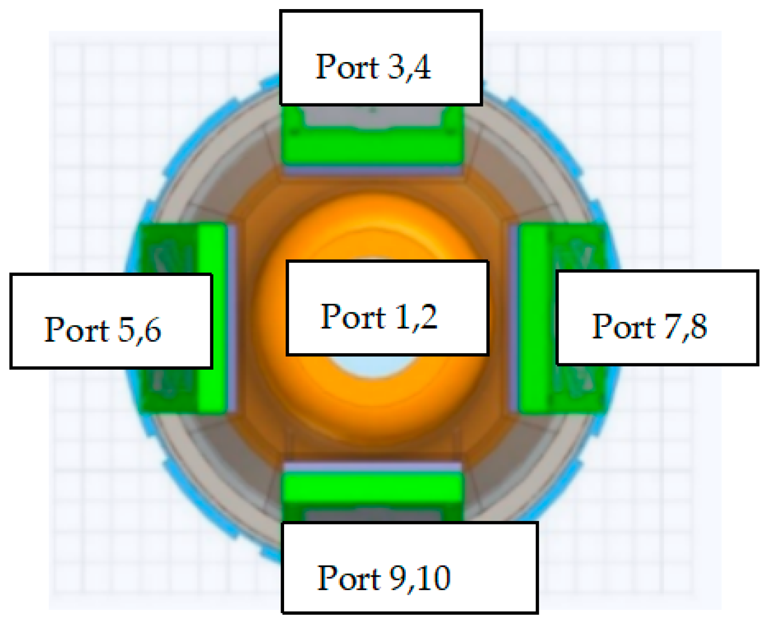
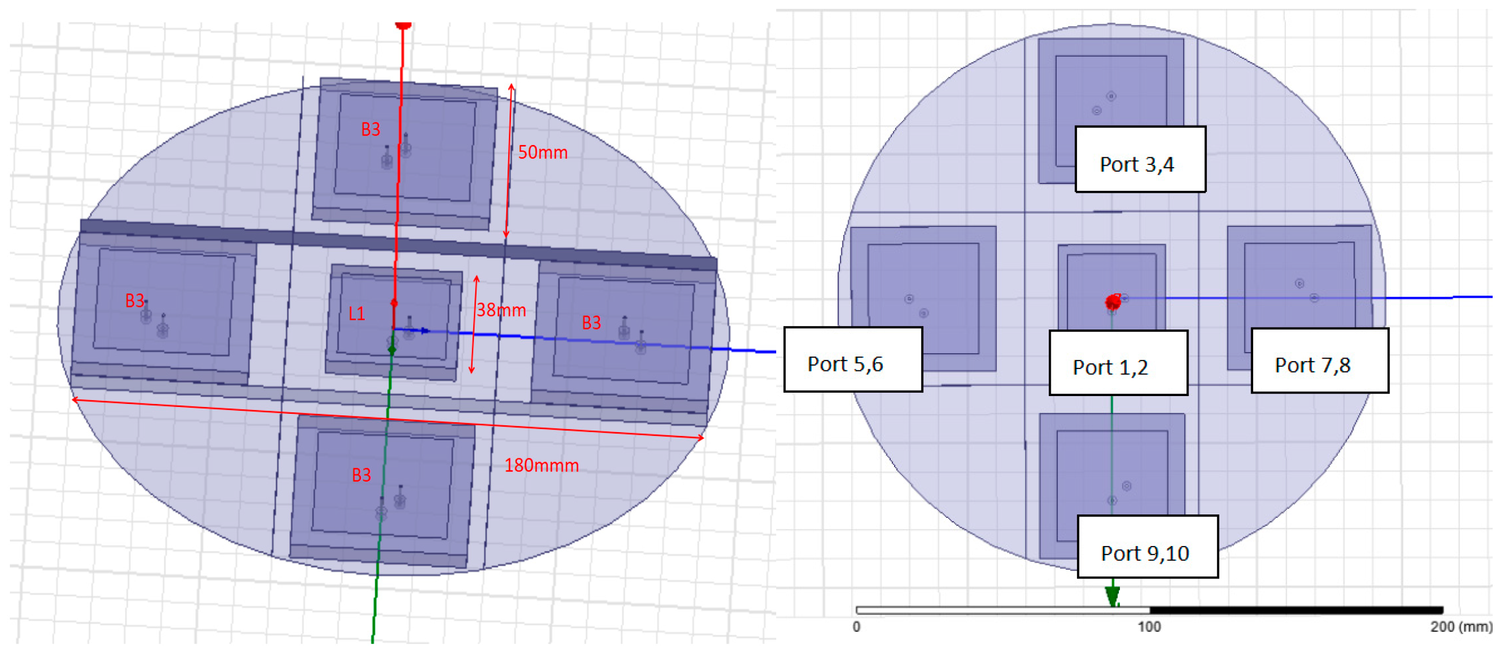
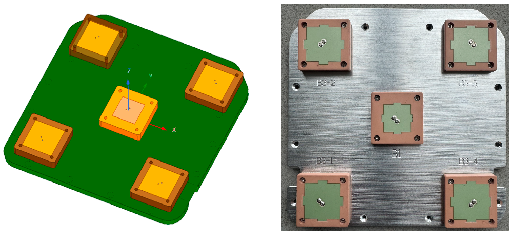
2. Proposed Array Antenna Structure and Dimensions

On the rectangular base, the center of the array is a BDS-B1 antenna, and the corners include 4 BDS-B3 antennas. The center frequency of BDS-B1 is 1561.098 MHz; BDS-B3 is 1268.52 MHz.
The design of the array antenna starts by designing a patch antenna with the specified dielectric constant (εr) and height (hs) so that 1.278 GHz resonant frequency can be achieved. To design a rectangular microstrip patch antenna for a specific resonant frequency (fr), the width (W) and length (L) of the patch should be computed. We choose L = W, so only need to calculate the W. The dimension of the patch can be calculated using the formula given below (1):
Width (W) of the patch:
w = c 2 2 ε r + 1
where C is the speed of light.
The design of the array antenna starts by designing rectangular patch antenna with the specified dielectric constant (εr) and height (h) so that B3-1.278 GHz and BDS-B1 1562 MHz resonant frequency can be achieved, as in Table 1.
The array spacing is less than or equal to half a wavelength and is placed on a rectangular base for simulation. The array element adopts a double-feed point structure, and the antenna size is 50 mm × 50 mm × 4 mm for the four corner B3 elements with port (3–10), and 38 mm × 38 mm × 4 mm for the middle B1 element port (1,2), as in Figure 5. The antenna array consists of three parts: a ceramic radome, metal parts, and a patch. The radome is composed of microcrystalline ceramic. The dielectric loss angle of this ceramic is about 0.004 and has good wave transmission performance. Incidentally, the Beidou B1 and GPS L1 can use the same frequency 1575 MHz.
To realize the circular polarization characteristics of microstrip antennas, use a two-point feeding technology with a phase difference of 90°. Anti-jamming antenna arrays require good consistency of antenna elements to improve the accuracy of beamforming algorithms. At the same time, to cover multiple operating frequency bands of Beidou and GPS, the antenna element should have good wideband circular polarization characteristics. In addition, in the corresponding working frequency range, the radiation characteristics of the antenna element are also high, the beam coverage should be wide, and the gain in the direction of low elevation angle should be high. Finally, to meet the installation requirements of a specific carrier platform, the large number of elements, the small spacing of the array [15,16], and the size of the antenna element should meet the requirements of miniaturization.
Based on the above design requirements, in this paper, 2 different-size microstrip patch antennas are used together in Figure 6, and the simulation verifies that the spacing between B1 and B3 elements is set to 0.341 wavelength of 57 mm, and the spacing of B3 element is set to 0.338 wavelength of 80 mm because, at this spacing, the phase difference of the signal received by each element is minimal, which makes the radiation or reception ability of the array antenna in a specific direction stronger, and further enhances the cross-correlation between each element in the array antenna.

3. Antenna Simulation Results

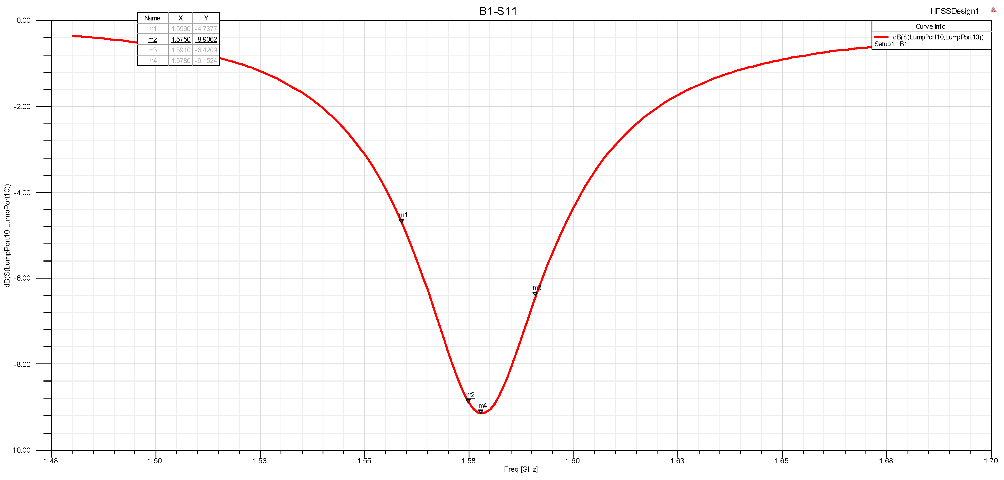
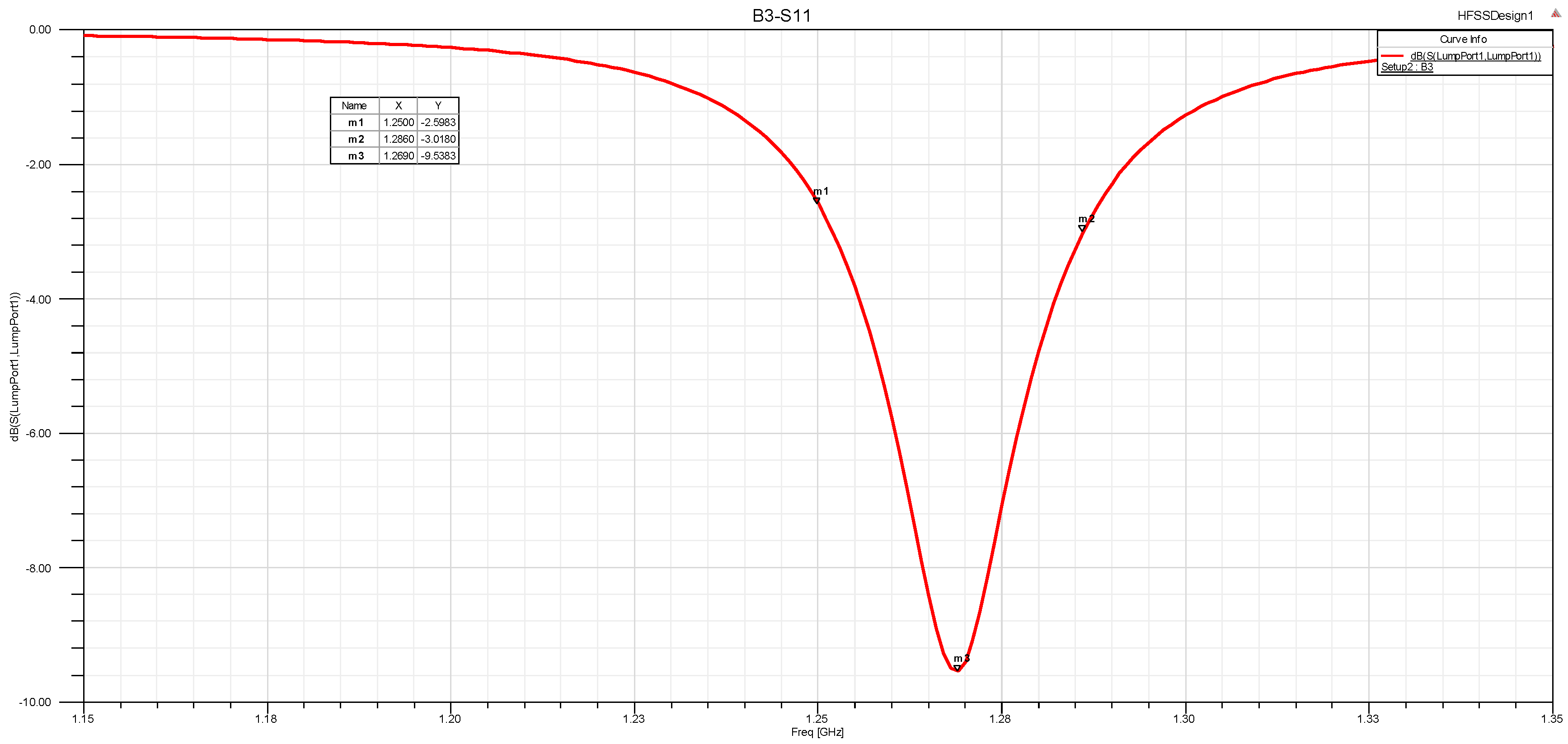
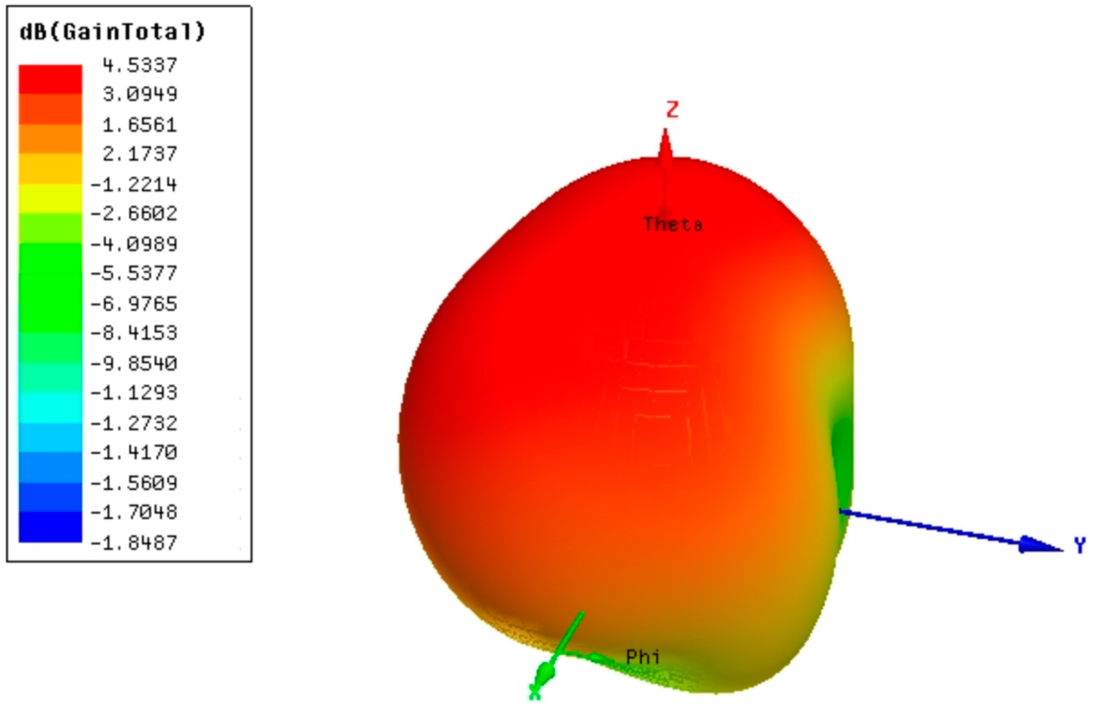
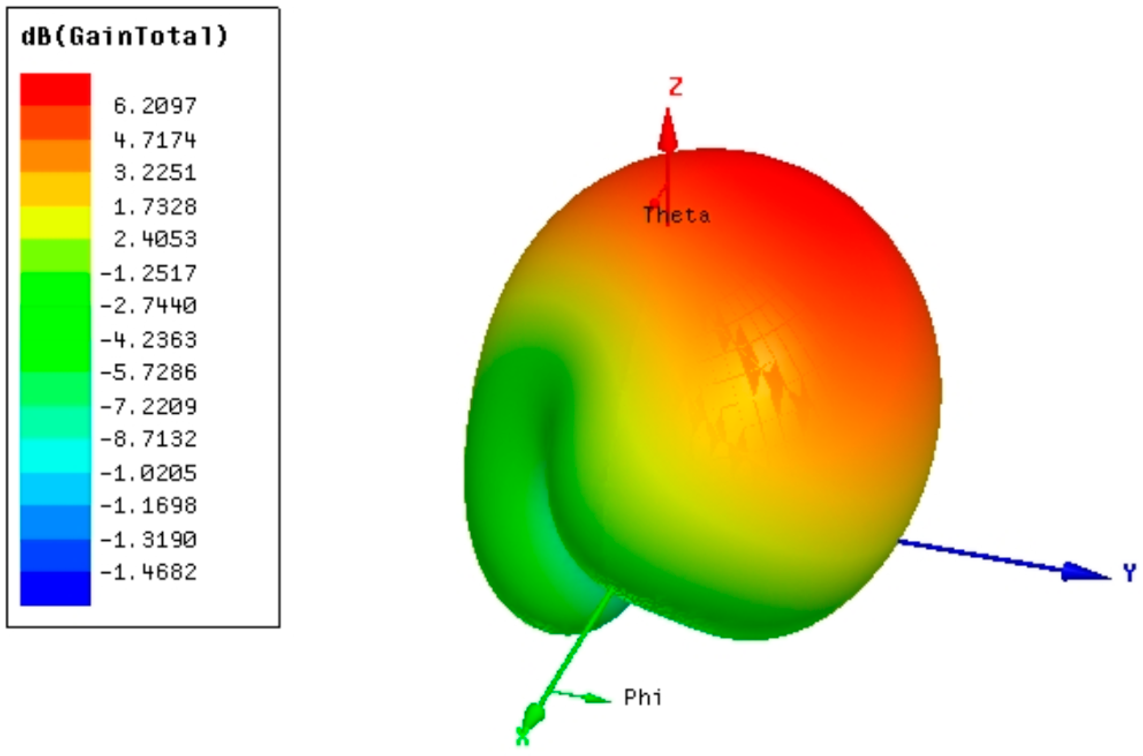
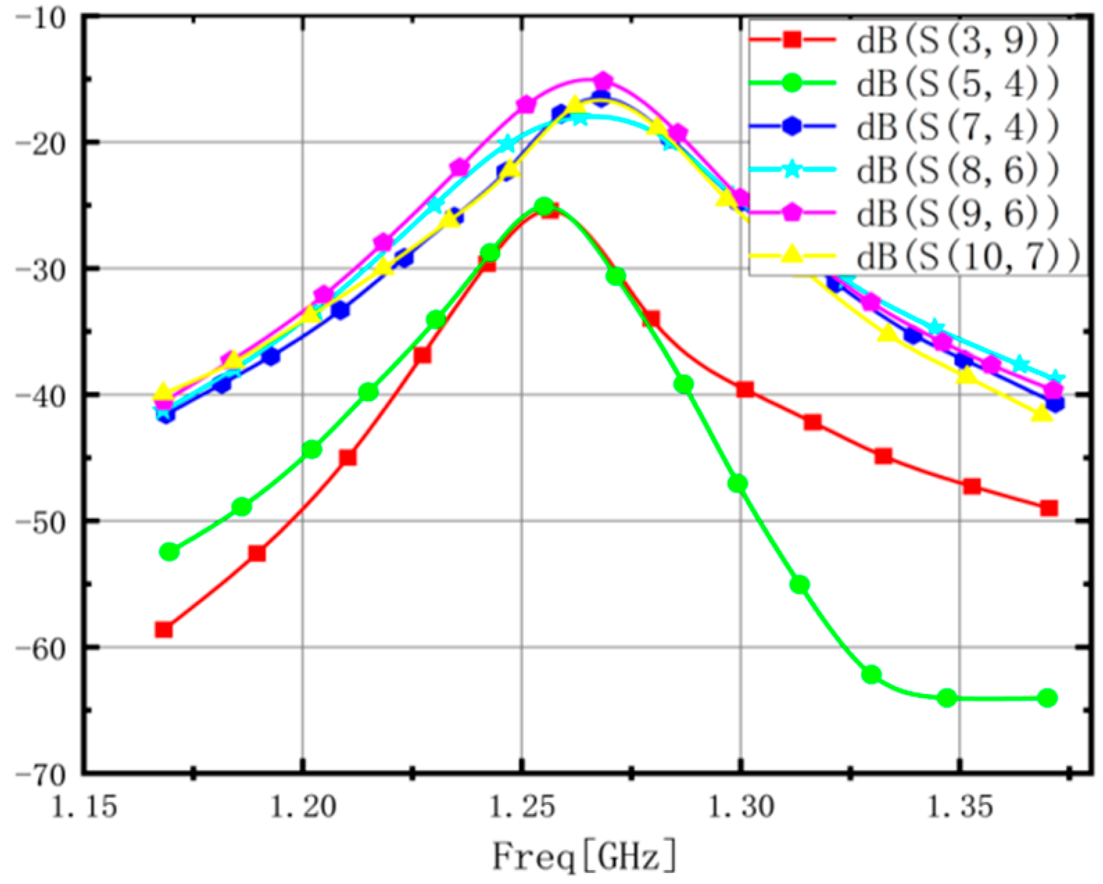
3.1. HFSS Simulation Result

To verify the antenna’s performance, a simulation analysis was performed using Ansoft HFSS software (https://www.ansys.com/products/electronics/ansys-hfss, 27 January 2025). B1 (1559.052~1591.788 MHz) of the Beidou Navigation Satellite System has the same frequency as L1 (1575 MHZ), so, for the HFSS simulation result we use L1 in Figure 6. The navigation antenna implements RHCP, and its radiation covers the upper hemisphere. All antenna arrays are designed with dual feed points for good circularly polarized axial ratio characteristics. The array unit adopts a single-layer microstrip structure. The L1/B1 S11 simulation S11 result is in Figure 6, B3 S11 simulation result in Figure 7, L1/B1 VSWR simulation result in Figure 8, B3 VSWR simulation result in Figure 9, B1 gain simulation result in Figure 10, B3 gain simulation result in Figure 11, B1/L1 RHCP simulation result in Figure 12, and B3 RHCP gain simulation result in Figure 13. The antenna B3 Gain is 6.21 dBi and B3 RHCP gain is 6.18 dBi.

3.2. Anti-Interference Performance

The anti-interference performance is caused by the size of the array spacing and the mutual coupling between the array elements, and the array spacing is designed to be 3/8 wavelength. Anti-jamming array antennas (Port 3,4; Port 5,6; Port 7,8; Port 9,10) in Figure 5 often need to have a high isolation index to ensure that the mutual coupling effect between the antenna elements is as small as possible. Generally speaking, the higher the isolation, the less interaction between the antennas, and the more stable the antenna performance. The BDS-B3 arrays (Port 3–10:S (3,9), S (5,4), S (7,4), S (8,6), S (10,7)) are isolated from each other with a minimum of 15.3 dB and a maximum of 30.0 dB, as shown in Figure 14. The S parameter is about −25 dB, demonstrating a good isolation antenna result and aiding the anti-jamming antenna performance.
We use the similar anti-interference antenna design as in Ref. [12] for the design of anti-jamming antenna system. The active Beidou anti-jamming antenna includes four antennas and four low-noise amplifiers in Figure 15. The satellite navigation signal received by the Beidou anti-jamming antenna is processed by the low-noise amplifying module, which amplifies the signal with low noise. Then, the processed signal goes through the radio frequency module.
Its main functions include three aspects. The first includes down-converting, amplifying, and filtering the signal. After processing, it is transformed into four IF signals, which are sent to the analog-to-digital converter chip. The second is to provide 62 MHz clock reference for the system. The third is to provide one B3 up-conversion channel. Then, the IF signal containing interference signal is processed by machine-learning-based anti-jamming baseband processing module. Then, NF (noise figure) is measured, and the relationship between NF and SNR is described below in Equation (2):
NF = (SNRi/SNRo) − 1
The practical implications scenario: NF measured is less than 1.8, set up a GPS receiver in Figure 16 operating in a jamming environment, and choose jamming types: broadband noise jamming, swept-tone jamming, and pulsed jamming.

4. Antenna Protype and Environment Test

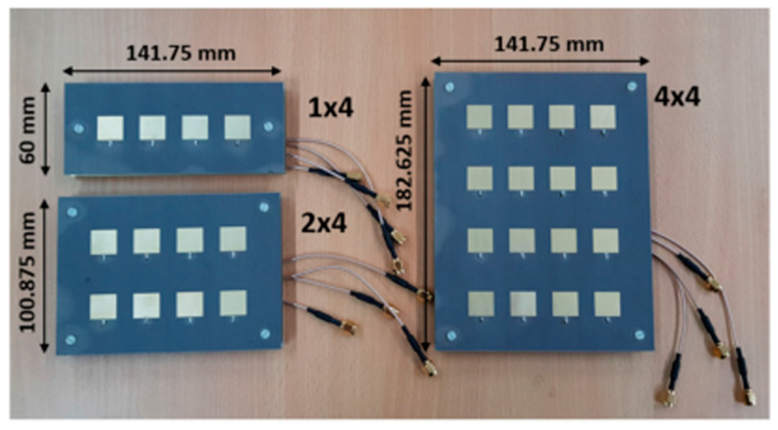
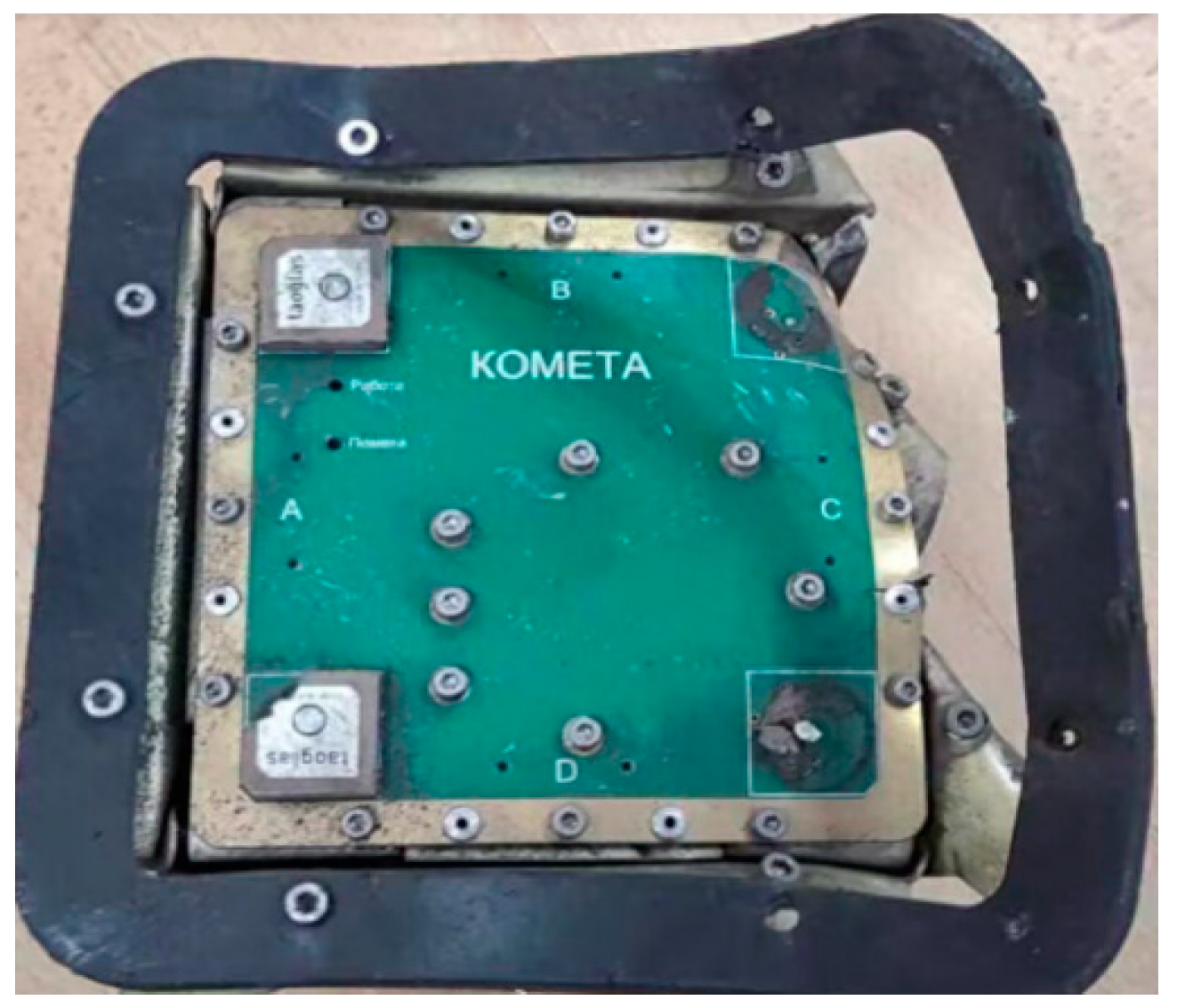
4.1. Protype Fabrication

The antenna is mainly used to receive the B1/B3 band of the BDS, the intermediate element receives the BDS-B1 band (Port 1,2), and the peripheral element receives the BDS-B3 band, and consists of a low-noise amplifier and a radome. To better approximate the electromagnetic boundary conditions in practical applications, we built an antenna model as presented in Figure 17.
Comparison table incorporating cost, manufacturability, and complexity ratings for aluminum-based antennas, PCB-based antennas, and RIS (reconfigurable intelligent surface) antennas, along with a detailed cost breakdown in Table 2.
Cost Breakdown
1. 
Aluminum-Based Antenna
Material Cost: $20–50/unit
Composite aluminum cores (ACCC cables with high tensile strength)
Surface treatments (shot blasting, spray coating)
Manufacturing Cost: $30–100/unit
CNC machining for structural components (large aluminum panels)
Labor-intensive assembly (riveting, autoclave curing)
Integration Cost: $10–20/unit
Testing for thermal stability (−40 °C to +400 °C tolerance)
2. 
PCB-Based Antenna
Material Cost: $5–10/unit
Standard FR4 substrates and copper traces
IPEX connectors and 50 Ω impedance matching
Manufacturing Cost: $3–15/unit
Batch production via automated PCB etching and lamination
Minimal post-processing (solder masking)
Integration Cost: $2–5/unit
Pre-tuned for frequencies like 2.4 GHz with 2 dB gain
3. 
RIS Antenna
Material Cost: $80–200/unit
Tunable dielectric/metamaterial substrates (liquid crystals, varactor diodes)
High-precision microelectronics for phase control
Manufacturing Cost: $100–300/unit
Additive manufacturing for lattice structures
Complex alignment of reconfigurable elements
Integration Cost: $20–50/unit
Software-defined control systems and calibration algorithms

4.2. Thermal Cycleing Test

From the Figure 18, Operating temperature range: −20 °C~400 °C. Test Equipment:
Thermal chamber capable of cycling between −40 °C and +400 °C (typical GNSS operating range). Data loggers to monitor temperature and humidity. Mechanical testing equipment (tensile tester, hardness tester). Vector network analyzer (VNA) to measure antenna performance (impedance S11). Test parameters’ temperature range: −40 °C to +400 °C. Cycle duration: 0.2 h (10 min at −20 °C; 10 min at +400 °C). Total cycles: 1000 cycles (simulating 5 years of operation).
Analysis result: Tensile strength decreases by ~8% after 1000 cycles due to microcrack formation. Surface roughness increases due to thermal expansion and contraction.
Analysis: Impedance matching degrades due to material warping, and gain decreases by ~10% after 1000 cycles. Radiation pattern distortion becomes significant, affecting signal reception.
Thermal cycling tests reveal significant material degradation over time, particularly in tensile strength, impedance matching, and gain. By selecting thermally stable materials and optimizing designs, the durability and performance of GNSS antennas can be significantly improved for harsh environments.

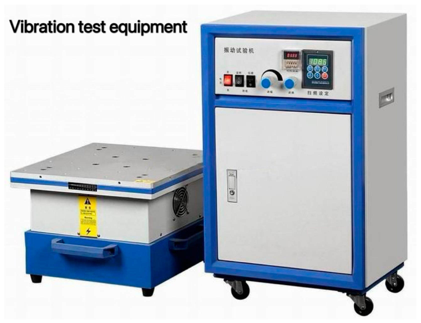
4.3. Vibration Test Result

From Figure 19, the vibration equipment unit type is Delta-VT300-C. This series of products are widely used in aviation, aerospace, electronics, instrumentation, electrical products, materials, components, equipment, etc., for anti-vibration testing and structural strength testing in order to analyze and evaluate the performance and behavior of test specimens under specified environmental conditions. After the test of random excitation force, 300 Kg. f r.ms and shock excitation force 600 Kg. f peak.

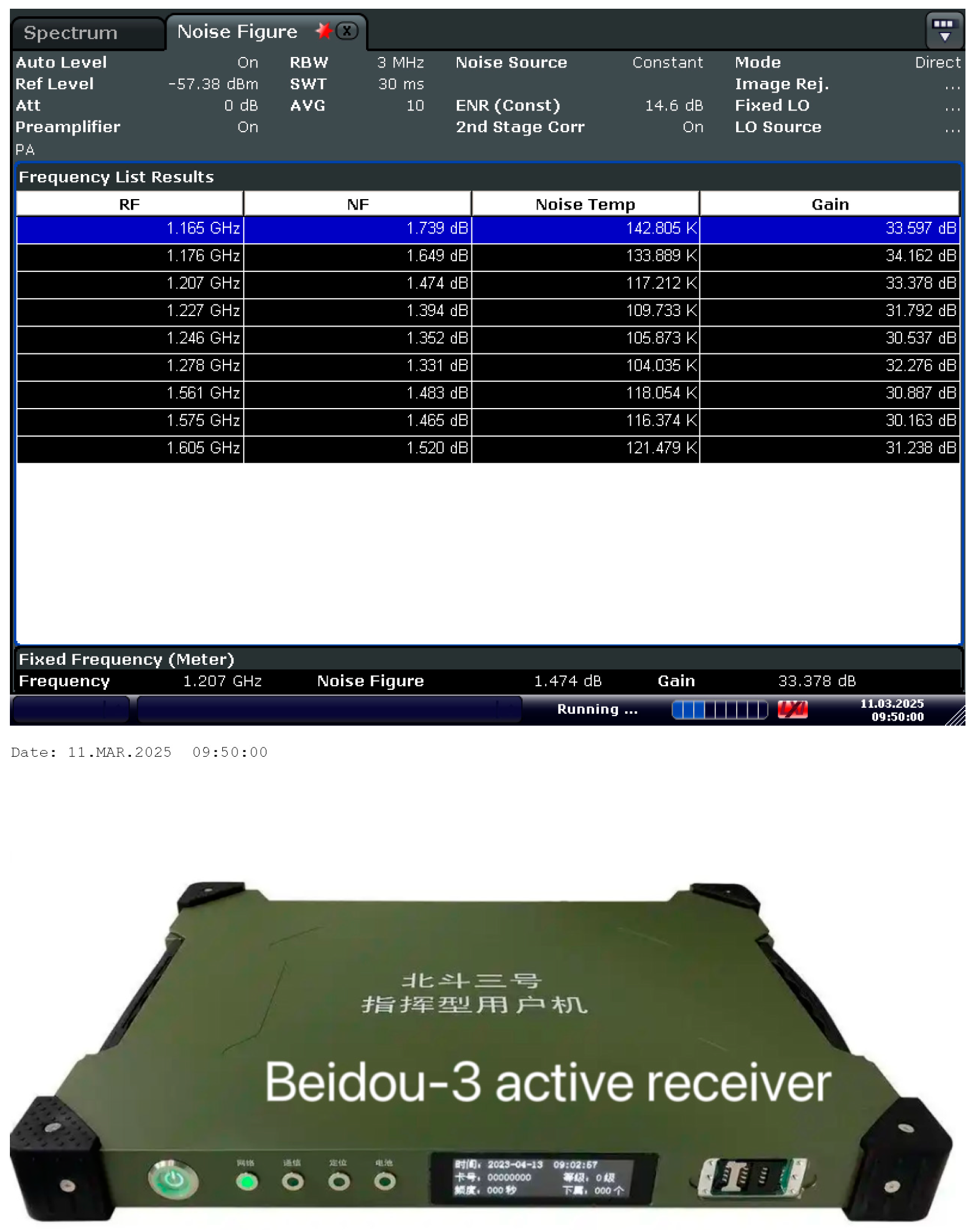
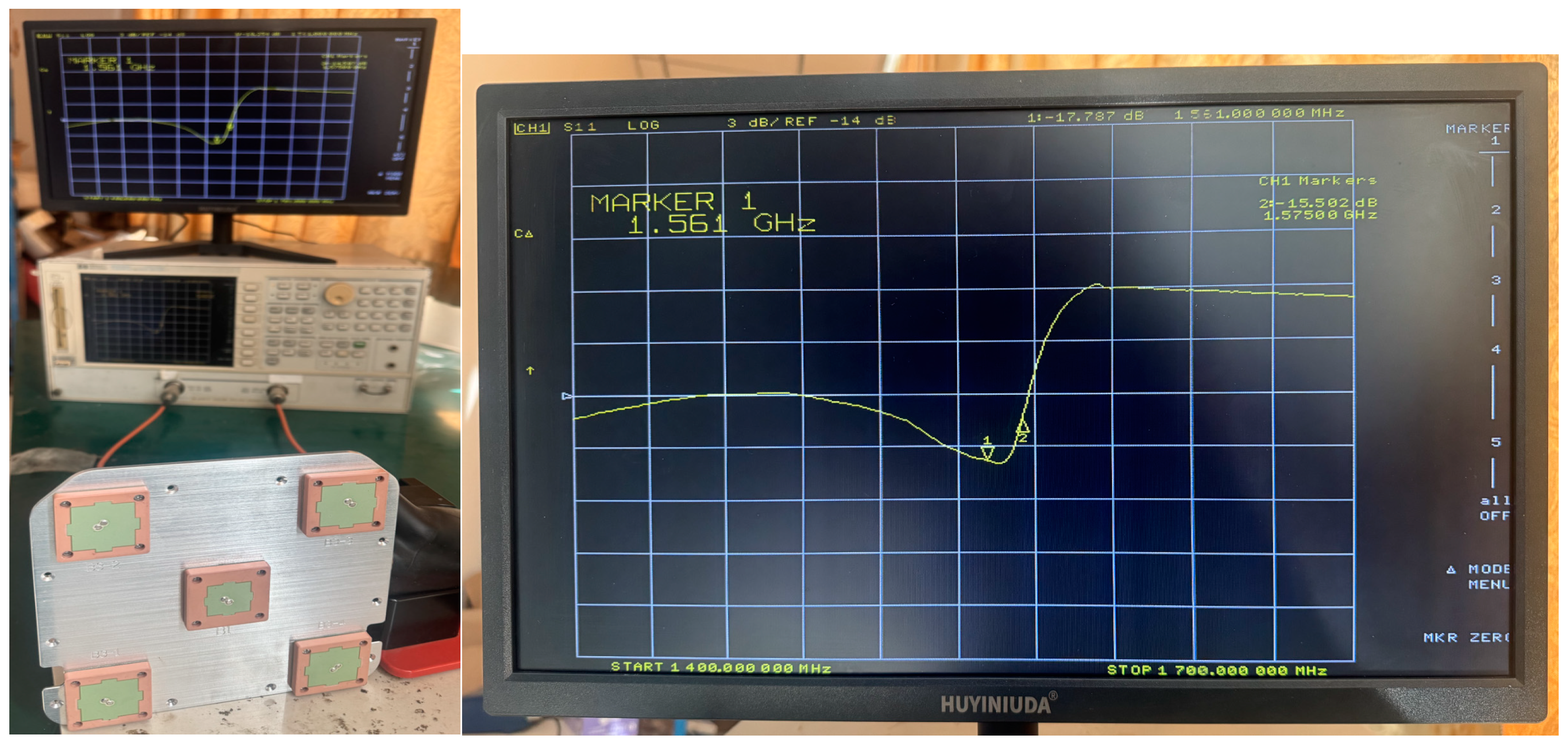
4.4. NWA 8753ES Test Result

After the thermal cycling test and vibration test, the antenna gain and S11 performance demonstrate no changes, as measured by Agilent 8753ES. The test setup is as in Figure 20. The S11 of B1 is −17 dB, and the S11 of B3 is −20 dB in Figure 21.

4.5. Comparison RF Performance with Some Data in the Reference Articles

The S11 parameters, gain, and RHCP gain simulated and measured are shown in Figure 7, Figure 8, Figure 9, Figure 10, Figure 11, Figure 12, Figure 13 and Figure 14. In both the B1 and B3 bands, the return loss of the center antenna is less than −9 dB. The B3 gain is 6.18 dBi. Here, the gain parameter measured in the 5.8 G frequency band is 5.95 dBi in Ref. [9]. As can be seen from Table 1, gain is better by 0.23 dB compared with that in Ref. [9]. As shown in Table 3, the radiation pattern of the two planes orthogonal at the corresponding frequencies of each B3 element in the selected literature [11] is compared with this paper. It can be seen that, compared with the 7-element antenna in Ref. [11], the 5-element antenna proposed in this paper has more economic advantages under the condition and much better gain. Table 1 compares the S11 and gains of the 4-element anti-jamming array antenna in Ref. [12] with the data in this paper. Under the premise of comparable gain, the antenna designed in this paper contains two frequency bands: B1 and B3.

5. Conclusions and Future Work

The antenna can cover Beidou B1 and B3 frequencies and GPS L1 in Figure 22. The Beidou antenna’s structural components are crafted from 7075 aluminum alloy and utilize high-temperature ceramic material technology, featuring a compact design and robust resistance to corrosion, making it particularly suitable for aviation and maritime environments. The antenna maintains stable operation at elevated temperatures and exhibits exceptional heat resistance.
The Beidou B1/B3 antenna can be adapted for dual-mode GNSS reception (Beidou + GPS) through moderate design changes such as bandwidth expansion and filter integration. Real-time multi-constellation switching requires wideband antenna designs and advanced receiver algorithms. This aluminum alloy antenna solution is highly versatile, covering Beidou B1/B3, GPS L1, and Galileo E1 frequencies, making it suitable for broader GNSS applications in Refs. [17,18,19].
Future efforts should focus on bandwidth expansion, receiver firmware updates, and prototyping stacked patch antennas with thermally stable materials. Challenges like impedance mismatch and radiation pattern distortion can be addressed using adaptive matching networks and rigid radomes with low thermal expansion coefficients. Finite element analysis (FEA) will further optimize radome geometry for thermal stability, ensuring global compatibility and enhanced performance.
The receiver and Beidou antenna can be integrated using an aluminum alloy structure. To ensure seamless operation across various systems, strict compatibility testing and verification are essential during software development. Future work should focus on designing universal interfaces to facilitate the integration of GNSS devices, such as receivers, antennas, and other components. Universal interfaces like Bluetooth can enable GNSS devices in Ref. [20] to connect and share data with other electronic systems effortlessly. Potential applications include aircraft wing communication antennas, shipborne communication antennas, GNSS antennas, and the integration of base station antennas in Ref. [21] with RF receiver modules, enhancing connectivity and functionality in diverse scenarios.

Author Contributions

Methodology, F.X.; Validation, X.Z.; Writing—original draft, F.X.; Writing—review & editing, F.X.; Supervision, X.Z. All authors have read and agreed to the published version of the manuscript.

Funding

This research received no external funding.

Data Availability Statement

No new data were created or analyzed in this study. Data sharing is not applicable to this article.

Acknowledgments

The authors would like to express their sincere gratitude to Xuxiao Wang for her valuable contributions to the preparation of the original draft and for her assistance with certain aspects of the laboratory work.

Conflicts of Interest

Author Feng Xu were employed by the company Suzhou Guozhixin Network Communication Co., Ltd. The remaining authors declare that the research was conducted in the absence of any commercial or financial relationships that could be construed as a potential conflict of interest.

References

  1. Shuangshan, Y.; Xuelong, H.; Jichao, Q. Design and implementation of Beidou anti-jamming antenna. In Proceedings of the 2017 13th IEEE International Conference on Electronic Measurement & Instruments (ICEMI), Yangzhou, China, 20–22 October 2017; IEEE: Piscataway, NJ, USA, 2017. [Google Scholar]
  2. Li, S.; Zhao, Y.; He, H.; Li, X.; Wang, W. The Design and Implementation of Data Link Terminal Based on Two Modes Satellite Communication. In Proceedings of the 2022 International Symposium on Networks, Computers and Communications (ISNCC), Shenzhen, China, 19–22 July 2022; IEEE: Piscataway, NJ, USA, 2022. [Google Scholar]
  3. Liang, Y.L.; Zhang, C.; Xing, L. A Compact Dual-Band Circularly Polarized Stacked Patch Antenna for GNSS Application. In Proceedings of the 2024 IEEE International Conference on Computational Electromagnetics (ICCEM), Nanjing, China, 15–17 April 2024; IEEE: Piscataway, NJ, USA, 2024. [Google Scholar]
  4. Yan, P.-P.; Hong, W.; Liu, J.; Kuai, Z.-Q.; Chen, J.-X. Investigations on RF front end for BeiDou satellite navigation system. In Proceedings of the 2005 Asia-Pacific Microwave Conference Proceedings, Suzhou, China, 4–7 December 2005; IEEE: Piscataway, NJ, USA, 2005. [Google Scholar]
  5. Zheng, W.C.; Zhang, L.; Li, Q.X.; Leng, Y. Dual-Band Dual-Polarized Compact Bowtie Antenna Array for Anti-Interference MIMO WLAN. IEEE Antennas Wirel. Propag. Lett. 2014, 62, 237–246. [Google Scholar] [CrossRef]
  6. Gaofeng, G. The Method and Test System for the Dielectric Properties of Radome Materials Under High Temperature Environment; University of Electronic Science and Technology of China: Chengdu, China, 2008. [Google Scholar]
  7. Li, X.; Ma, R.; Cai, H.; Pan, Y.-M.; Zhang, X.Y. High-Gain Dual-Band Aperture-Shared CP Patch Antenna with Wide AR Beamwidth for Satellite Navigation System. IEEE Antennas Wirel. Propag. Lett. 2023, 22, 1888–1891. [Google Scholar] [CrossRef]
  8. Tian, Y.; Zhao, H.; Ouyang, J. A coupled-feed microstrip Yagi antenna with high temperature resistance. In Proceedings of the 2023 16th UK-Europe-China Workshop on Millimetre Waves and Terahertz Technologies (UCMMT), Guangzhou, China, 31 August–3 September 2023; pp. 1–3. [Google Scholar] [CrossRef]
  9. Zeng, X.; Hu, Z.; Chen, Q.; Wei, X.; Huang, K. A Broadband Circularly Polarized High-Temperature Superconductor Microstrip Antenna for Space Applications. IEEE Antennas Wirel. Propag. Lett. 2018, 17, 2179–2182. [Google Scholar] [CrossRef]
  10. Dasari, S.A.; Williamson, T.G.; Ghalichechian, N. Silicon Carbide Slot Dielectric Resonator Antenna for High Temperature and Power Applications. In Proceedings of the 2023 IEEE International Symposium on Antennas and Propagation and USNC-URSI Radio Science Meeting (USNC-URSI), Portland, OR, USA, 23–28 July 2023. [Google Scholar]
  11. Fu, Y.; Shang, F.; Fu, Z. Anti-interference satellite navigation array antenna. In Proceedings of the 2023 IEEE 11th Asia-Pacific Conference on Antennas and Propagation (APCAP), Guangzhou, China, 22–24 November 2023. [Google Scholar]
  12. Qi, N.; Zhang, Z.; Dong, N.; Guo, M.; Kong, M. A Design of Conformal Anti-Jamming Antenna System. In Proceedings of the 2022 International Symposium on Networks, Computers and Communications (ISNCC), Shenzhen, China, 19–22 July 2022. [Google Scholar]
  13. Tan, M.C.; Li, M.; Abbasi, Q.H.; Imran, M.A. A Wideband Beamforming Antenna Array for 802.11ac and 4.9 GHz in Modern Transportation Market. IEEE Trans. Veh. Technol. 2020, 69, 2659–2670. [Google Scholar] [CrossRef]
  14. Zhang, Y.-M.; Li, J.-L.; Wang, B.-Z. A Dual-Band Dual-Polarized Antenna Array with Improved Isolation. In Proceedings of the 2018 International Conference on Microwave and Millimeter Wave Technology (ICMMT), Chengdu, China, 7–11 May 2018. [Google Scholar]
  15. Sang, L.; Wang, J.; Liu, Z.; Wang, W.; Huang, W.; Tu, H. A UWB Metal Waveguide Slot Array Antenna Based on Hybrid Resonant Structural Components. IEEE Antennas Wirel. Propag. Lett. 2023, 22, 923–927. [Google Scholar] [CrossRef]
  16. Li, L.; Feng, B.; Wang, M.; Zeng, Q. A low-profile dual-polarized magneto-electric dipole antenna with metamaterial loading and anti-interference capability. In Proceedings of the 2017 IEEE 5th International Symposium on Electromagnetic Compatibility (EMC-Beijing), Beijing, China, 28–31 October 2017. [Google Scholar]
  17. Liu, G.; He, L.; Wang, S.; Zhang, R.; Wang, X. Design of a K-band Wideband Circularly Polarized Micro-strip Array Antenna. In Proceedings of the 2020 International Symposium on Antennas and Propagation (ISAP), Osaka, Japan, 25–28 January 2021. [Google Scholar]
  18. Becker, D.; Hinüber, E.v. Multi-pass phase-differential GNSS ambiguity fixing for post-processing applications. In Proceedings of the 2023 DGON Inertial Sensors and Systems (ISS), Braunschweig, Germany, 24–25 October 2023. [Google Scholar]
  19. Siebert, C.; Bochkati, M.; Pany, T.; Meurer, M. Comparison of Different Vector Tracking Architectures in Challenging Urban Environments Using the TEX-CUP Data Set. In Proceedings of the 2024 11th Workshop on Satellite Navigation Technology (NAVITEC), Noordwijk, The Netherlands, 11–13 December 2024. [Google Scholar]
  20. Völk, F.; Schlichter, T.; Kumar, S.; Schwarz, R.T.; Knopp, A.; Hammouda, M.; Heyn, T.; Querol, J.; Chatzinotas, S.; Kapovits, A. 5G Non-Terrestrial Networks with OpenAirInterface: An Experimental Study Over GEO Satellites. IEEE Access 2024, 12, 155098–155109. [Google Scholar] [CrossRef]
  21. Wang, W.; Wen, Y.; Liu, Y. Design and Testing of a Specialized Antenna Array for GNSS Receiver Anti-Interference Enhancement. In Proceedings of the 2024 International Conference on Electromagnetics in Advanced Applications (ICEAA), Lisbon, Portugal, 2–6 September 2024; IEEE: Piscataway, NJ, USA, 2024. [Google Scholar]
Figure 1. Physicality drawing of Ref. [11].
Electronics 14 01555 g001
Figure 2. Physicality drawing of Ref. [12].
Electronics 14 01555 g002
Figure 3. Physicality drawing of Ref. [13].
Electronics 14 01555 g003
Figure 4. KOMETA PCB antenna.
Electronics 14 01555 g004
Figure 5. Beidou antenna array (middle is B1; conners include 4 B3 antennas).
Electronics 14 01555 g005
Figure 6. B1 S11 simulation result.
Electronics 14 01555 g006
Figure 7. B3 S11 simulation result.
Electronics 14 01555 g007
Figure 8. B1 VSWR simulation result.
Electronics 14 01555 g008
Figure 9. B3 VSWR simulation result.
Electronics 14 01555 g009
Figure 10. B1 Gain simulation result.
Electronics 14 01555 g010
Figure 11. B3 Gain simulation result.
Electronics 14 01555 g011
Figure 12. B1 RHCP simulation result.
Electronics 14 01555 g012
Figure 13. B3 RHCP Gain simulation result.
Electronics 14 01555 g013
Figure 14. Mutual coupling and isolation between BDS-B3 arrays.
Electronics 14 01555 g014
Figure 15. Active Beidou anti-jamming Diagram.
Electronics 14 01555 g015
Figure 16. NF measured and Active Beidou Receiver.
Electronics 14 01555 g016
Figure 17. Antenna protype model and three-dimensional drawing.
Electronics 14 01555 g017
Figure 18. The thermal cycling test equipment BST-XHE-415T.
Electronics 14 01555 g018
Figure 19. The vibration equipment Delta-VT300-C.
Electronics 14 01555 g019
Figure 20. The B1 S11 test Result.
Electronics 14 01555 g020
Figure 21. The B3 S11 result.
Electronics 14 01555 g021
Figure 22. GNSS frequency band.
Electronics 14 01555 g022
Table 1. Demensions of the antenna structure.
Substrate thickness, hs,4 mm
Width of the B1 Substrate, W-subB137 mm
Width of the B3 Substrate, W-subB350 mm
Width of the B1-patch, W-B130.6 mm
Width of the B3-patch, W-B338.1 mm
Diameter of GND r95 mm
Height of GND S-H4 mm
Length of GND S-L180 m
Table 2. The Cost comparison of Aluminum-Based vs. PCB-Based vs. RIS Antennas.
MetricAluminum-Based AntennaPCB-Based AntennaRIS Antenna
CostHigh (50–150/unit)Low (10–30/unit)Very High (200–500+/unit)
ManufacturabilityModerate: Requires CNC machining, structural assembly, and surface treatmentHigh: Mass-producible via standard PCB etching and lamination processesLow: Complex fabrication of tunable metasurfaces and control electronics
ComplexityModerate: Structural design challenges (e.g., thermal expansion, weight)Low: Simple planar design with predefined impedance and frequency tuningVery High: Requires dynamic phase control and integration with AI/ML systems
Table 3. Comparison RF performance of Refs. [9,10,11,12] and this data in this article.
Data from Ref. [9]Index5.8 GHz Gain (dBi)
Single antenna
5.8 GHz-S11 (dB)
Simulation Values5.95NA
Measured ValuesNANA
Data in this articleIndexB3-RHCP Gain(dBi)
Single antenna
B1-S11 (dB)
(1561.098 MHz)
Simulation values 6.18−9.3
Measured valuesNA−17
Data from Ref. [10].Index31 GHz Gain (dBi)
Single antenna
31 GHz-S11 (dB)
Simulation values5.5−10
Measured valuesNANA
Data from Ref. [11].IndexBDS-B3-RHCP Gain (dBiC)
Single antenna
GPS-L1-S11 (dB)
(1575.42 MHz)
Simulation values−5−10
Measured valuesNANA
Data from Ref. [12].Index4.9 GHz Gain (dBi)
Total 4 array antenna
4.9 GHz -S11 (dB)
Simulation values15−10
Measured valuesNANA
Disclaimer/Publisher’s Note: The statements, opinions and data contained in all publications are solely those of the individual author(s) and contributor(s) and not of MDPI and/or the editor(s). MDPI and/or the editor(s) disclaim responsibility for any injury to people or property resulting from any ideas, methods, instructions or products referred to in the content.

