Article

A Design and Implementation of High-Efficiency Asymmetric Doherty Radio Frequency Power Amplifier for 5G Base Station Applications

School of Urban Railway Transportation, Shanghai University of Engineering Science, Shanghai 201620, China
*
Author to whom correspondence should be addressed.
Electronics 2025, 14(8), 1586; https://doi.org/10.3390/electronics14081586
Submission received: 19 March 2025 / Revised: 9 April 2025 / Accepted: 10 April 2025 / Published: 14 April 2025

Abstract

:
Utilizing asymmetric Doherty technology, this paper designs a high-efficiency radio frequency (RF) power amplifier (PA) for 5G base station applications. To improve the performance of PA and narrow the gap between simulations and practices, we use compatibility methods to design the circuit, which keeps the layout dynamically adjustable. By incorporating redundant U-shaped microstrip lines, the impedance matching network can be dynamically fine-tuned during debugging based on real-time hardware conditions. Furthermore, independent debugging paths for both main and auxiliary amplifiers are designed to enable the multi-stage debugging strategy. Performing separate debugging for each branch first, followed by combined debugging ensures both amplifiers achieve optimal operation states. The proposed strategy improves debugging efficiency while achieving precise parameter optimization. To verify the feasibility of the scheme proposed in this paper, we use CGHV40030F transistors to design a Doherty PA worked at 3.5 GHz and complete the hardware implementation and tests. Simulations and practice results prove that the architecture of asymmetric Doherty increases the back-off efficiency, and the compatibility design can make debugging easy and align the practice results closely with the simulations. We observe the saturation drain efficiency of 73.5% and the back-off efficiency of 47.5% from measurements, which confirms the effectiveness of the proposed compatibility design approach.

1. Introduction

With the rapid development of wireless communications, complex modulation techniques are commonly used to improve spectrum efficiency [1], which results in a high peak to average power ratio (PAPR) of modulation signals such as OFDM. The usage of modulation signals makes the specifications of PA more stringent [2]. Despite the fluctuation of the input signal within a certain range, the efficiency of the PA should maintain within a small dynamic range with a high level. Recently, scholars have studied and proposed a variety of power back-off techniques [3,4], also named efficiency enhancement techniques, to meet high-efficiency requirements. Bias modulation [5], which dynamically adjusts the static bias point of PA transistors to achieve localized efficiency optimization with low complexity, is suitable for narrowband and low-cost systems, but struggles to meet the ultra-wideband (UWB) and high-gain requirements of 5G. Out-phasing [6], leveraging constant-envelope amplification characteristics, demonstrates excellent back-off efficiency and linearity, but its stringent signal synchronization requirements lead to high hardware complexity, high cost, and great loss, thereby limiting large-scale adoption. Digital Doherty architecture [7] enhances the back-off efficiency range and wideband adaptability of the conventional Doherty design through dynamic input signal allocation and automated parameter optimization. However, the abundance of variables, high optimization difficulty, and reliance on advanced manufacturing processes all limit its potential for widespread application envelope elimination and restoration (E&ER) [8], decomposing signals into envelope and phase components processed by switching-mode and linear amplifiers respectively, achieves high theoretical efficiency. Implementation difficulties in ultra-wideband systems restricts its compatibility with modern communication standards and relegates it primarily to low-frequency, high-power applications. Envelope tracking (ET) [9], optimizing efficiency through dynamic supply voltage adjustment, exhibits superior back-off efficiency and wideband support capabilities with a broad dynamic power range, making it a mainstream solution for base stations. Its dependency on highly complex and costly wideband power modulators restricts its long-term reliability and large-scale deployment in 5G base stations. Broadening its use cases requires advancing power chip integration, lowering costs, and addressing thermal stress and EMI challenges induced by dynamic power delivery.
Compared with other techniques, the PA designed with the Doherty architecture has better characteristics [10,11]. The Doherty architecture, which coordinates the operation of main and auxiliary amplifiers, offers structural simplicity, low cost, and high efficiency across a wide back-off range while supporting high-power output and high linearity, making it particularly prominent in high-power and broadband scenarios. Furthermore, it demonstrates distinct advantages over prior technologies in specific applications. In multi-band concurrent operation scenarios, compared to outphasing technology, the Doherty architecture eliminates the need for complex phase alignment and signal combining circuits, enabling more stable and efficient power synthesis. For high instantaneous bandwidth requirements, unlike E&ER, it avoids stringent demands on envelope tracking bandwidth and synchronization accuracy, achieving high efficiency with enhanced robustness. In high-power base stations, compared to ET techniques, the Doherty architecture operates under a fixed supply voltage, removes reliance on high-complexity broadband power modulators, mitigates thermal management challenges, and ensures superior long-term reliability. Furthermore, it is convenient to combine the DSP techniques such as Digital Pre-Distortion (DPD). The Doherty architecture can effectively address nonlinearity issues through DPD. For instance, in scenarios employing combined load modulation to extend efficiency range, DPD compensates AM-PM distortion, achieving high linearity [12]. In wideband applications, when applied to distributed Doherty configurations, DPD mitigates gain compression and nonlinear phase distortion, thereby enabling compatibility with concurrent multi-band operation [13]. Therefore, with high-performance, low design cost, and easy implementation, the Doherty PA attracts more and more attention and is commonly utilized for 5G mobile communication base station applications [14].
In symmetric Doherty architectures, the main-to-auxiliary power ratio is fixed at 1:1, with the back-off point typically occurring at 6 dB. It demonstrates a significant improvement in peak drain efficiency compared to conventional techniques and performances excellently in multiple scenarios. However, its limited efficiency back-off range imposes constraints in high-demand applications. Asymmetric Doherty architectures address this limitation through optimized power ratio configurations by increasing the auxiliary amplifier’s power proportion, thereby maintaining high efficiency even in deep back-off regions. The inherent bandwidth constraints of Doherty architectures stem from the narrowband characteristics of the λ / 4 impedance transformer and the stringent phase synchronization requirements between main and auxiliary amplifiers. In contrast, asymmetric Doherty architectures employ decoupled carrier and auxiliary amplifier paths, exemplified by independently optimized impedance matching networks for each branch, which reduce frequency sensitivity and enable bandwidth extension.
While the asymmetric Doherty architecture typically demonstrates high performance in circuit design simulations, a significant performance gap between simulations and practical implementations is often observed due to fabrication error and process variations. To address this challenge, this paper proposes a novel circuit compatibility design methodology that maintains a dynamically adjustable layout. By utilizing an independent multi-stage debugging strategy and adjusting redundant U-shaped microstrip lines, the proposed approach effectively bridges the gap between hardware implementation and simulation, thereby enhancing the power amplifier performance. This paper designs an asymmetric Doherty PA worked in 3.4~3.6 GHz. Furthermore, we complete the hardware implementation and tests. This paper is organized as follow. The fundamentals of PA are introduced in Section 2. Section 3 elaborates on the design of the asymmetric Doherty PA and simulations. Section 4 shows the hardware tests and results, followed by conclusions in Section 5.

2. Fundamentals of the Doherty Architecture

2.1. Analyses of the Symmetric Doherty PA

The classical Doherty PA is symmetric and consists of a 3 dB filtering power divider with an equal output power ratio, two power amplification transistors, and a load modulation network, shown as in Figure 1. The identical transistors are used in both branches of the PA. One works in class AB to amplify the carrier signal as the main amplifier, and another works in class C to boost the peaking signal as an auxiliary amplifier [15,16]. The key to the Doherty PA is the active load-pull technique, which means adjusting the load impedance by supplying a specific current to an active device from another active device. Therefore, the load impedance changes with these two active devices rather than being fixed [17]. This technique makes the carrier amplifier achieve saturation fast and stay in a high-efficiency working condition, which is the key to maintaining the Doherty PA consistent and efficient in the whole back-off area [18].
However, there are some intrinsic defects in the practical applications of the traditional symmetric Doherty. Despite the power divider of the symmetric Doherty supplying the identical input power to two transistors of the PA, they work in different states. The carrier amplifier is biased in class AB. The peaking amplifier is still personal in class C [19]. The output current of the auxiliary amplifier is less than that of the main amplifier, and there is a corresponding relationship between the output power [20]. The output impedance of the main amplifier is 100 ohms when it works in the low-power region. It’s hard to pull down to 50 ohms even it works in high-power region. Based on the active load-pull principle, the output power of the symmetric Doherty PA must decrease in this usage scenario. In general, the back-off of the symmetric Doherty PA can only handle up to 6 dB. The small back-off limits the enhancement of the efficiency of the PA [21]. Meanwhile, as complex modulation is widely used in wireless communications, the circuit design of the PA should satisfy the requirements of high PAPR and the large back-off [22]. The emergence of the asymmetric Doherty PA solves the above problems.

2.2. The Principles of the Asymmetric Doherty PA

The Doherty PA can be called asymmetric Doherty PA, as long as there is any difference between the two branches of Doherty PA. There are three possible forms: unequal power inputs, unequal power syntheses, and the different drain voltages of two transistors [23]. The asymmetric Doherty PA with unequal power inputs utilizes the power divider with an unequal power ratio to supply higher power inputs to the peaking amplifier, which improves the output of the peaking amplifier. Another reason why this paper uses the asymmetric Doherty PA with this form is that it can also raise the back-off, the efficiency, and the output power [24]. According to the active load-pull method, this paper optimizes the impedance matching network. Based on the principle of impedance matching at the junction point, this paper composes the load modulation network. The techniques utilized in this paper help the PA improve the output power.
The voltage back-off α (dB) of an asymmetric Doherty PA is written as,
α = 20 lg 1 γ + 1 ,
where γ = P p / P c , P p and P c are the power capability of the peaking and the carrier amplifier, respectively. When γ = 1 , it is a classical symmetric Doherty PA. The carrier amplifier has the same input power as the peaking amplifier, and the maximum back-off is about 6 dB. When γ = 2 , the back-off approaches 9.5 dB. When γ = 3 , the back-off can reach 12 dB with the continuous growth of the peaking amplifier power. Briefly, with the increase of γ , the input power of the carrier amplifier is decreasing, and the input power of the peaking amplifier is increasing. The peaking amplifier can effectively compensate for the output current once it is turned on. Correspondingly, it improves the pulling capacity to the carrier amplifier [25]. However, considering the other indicators, the overall performance may degrade if γ is more significant. Therefore, we use CMX35Q05 (RN2 Technologies Co., Pyeongtaek-si, Republic of Korea) with the power ratio of 1:1.5 as the power divider to design an asymmetric Doherty PA with high back-off efficiency and high output power.

3. The Asymmetric PA Design and Simulations

3.1. The Bias Circuit, Matching Network, and Power Divider

To ensure that the practical circuit performance is as close to simulations as possible, this paper uses the compatibility method to design a high-efficiency asymmetric Doherty PA that worked in 3.4 GHz∼3.6 GHz for 5G applications. The effectiveness of this methodology is validated by comparing simulations based on Advanced Design System (ADS) [26] with measurements. The results demonstrate that this method is effective. We choose Cree CGHV40030F (Cree Co., Durham, NC, USA) transistors as the peak and carrier amplifiers to ensure the practical PA could be highly efficient with high output power. This transistor is a new generation of high-electron-mobility GaN devices with high power density, high power output, and high efficiency [27]. The print circuit board (PCB) is Rogers 4350B (permittivity ε r = 3.66 , thickness H = 20 mil and copper foil thickness T = 35 μm).
In designing an asymmetric Doherty PA, it’s necessary to prepare the carrier and peaking amplifiers separately. Firstly, we set the different bias voltages to ensure the two transistors work in class AB and class C, respectively. Referencing the drain voltage 50 V of the transistor given by the datasheet, the gate voltage of the carrier amplifier is −2.8 V, and the gate voltage of the peaking amplifier is −6 V by static scanning. Two transistors work in the different conditions so two branches of the PA have the different matching impedances. To obtain the optimum impedances for designing the matching network, it is necessary to operate load pull and source pull of two branches, respectively. Utilizing the auxiliary design platforms of the ADS, the optimal source impedance and load impedance of the amplifier worked in class AB are determined to be (7.321 + j × 4.580) Ω and (2.53 − j × 8.01) Ω . The corresponding values of the amplifier worked in class C are (4.711 + j × 8.45) Ω and (2.528 − j × 8.457) Ω , respectively. Depending on these optimum impedances, the conjugate matching circuits can be designed by Smith circle theory to maximize output power [28,29]. Furthermore, we utilize the parallel open-circuit microstrip line to make the practical circuit debugging more convenient and fast. The width of the microstrip line of the bias circuit depends on the current, and the width of the gate bias circuit and the drain bias circuit are both 1mm. The power divider CMX35Q05 with unequal power ratio utilized in this design presents low insertion loss, sharp rejection, and large bandwidth in favor of the stability and good performance of the circuit.

3.2. Offset Line Techniques

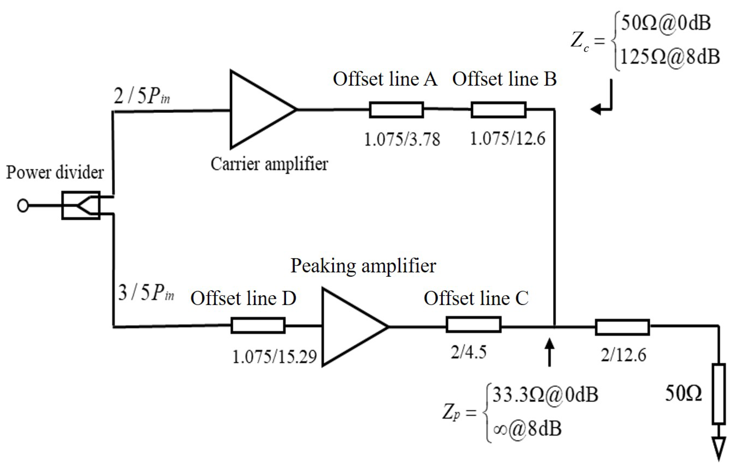
Considering the influence of the bias circuit, the matching circuit, and the power divider, it is also necessary to utilize offset techniques to improve the circuit performance, as shown in Figure 2. The offset line A, located at the carrier amplifier terminal, matches the phase of the terminal impedance to the load impedance, increasing the back-off efficiency [30]. The offset line B is a quarter wavelength microstrip line to realize the impedance transformation. The offset line C, located at the peaking amplifier terminal, is adjusted to an appropriate length. When the peaking amplifier has not yet been opened, the offset line C can pull up the terminal impedance and suppress the power leakage of the carrier amplifier [31]. The offset line D corrects the phase difference introduced by impedance transformation networks and the other offset lines mentioned previously to maximize the output power at the summing node [32,33].

3.3. Main Parameters and Simulations

According to the design principles described above, the main parameters of the asymmetric Doherty PA are calculated and shown in Figure 2. The output impedance of the carrier amplifier Z c is 50 Ω . The output impedance of the peaking amplifier Z p is 33.3 Ω at the saturation power point because the power ratio of the power divider γ was 1:1.5. Therefore, the resistance of the quarter wavelength offset line B should be 50 Ω , which leads to a length of 12.6 mm and a width of 1.075 mm. Similarly, the width of the offset line C is 2 mm. As offset line C forces the PA back, the output terminal of the peaking amplifier is open-circuit. Therefore, the output impedance of the peaking amplifier is pulled to a significant value at the Smith circle, which leads to the length of the offset line C being 4.5 mm. To ensure that the output impedance matches the load impedance at the back-off point and the match state is not changed at the saturation point, the width and the length of the offset line A are 1.075 mm and 3.78 mm, respectively, by simulations. To keep the phase of the output signal of one branch aligned with another, the width and the length of the offset line D are 1.075 mm and 15.29 mm, respectively. According to the impedance transform formula
Z T = Z 0 Z L ,
where Z T , Z 0 and Z L are the impedances of the transform line, the summing point, and the load, respectively. The width and the length of the transformed line are 2 mm and 12.6 mm, respectively.
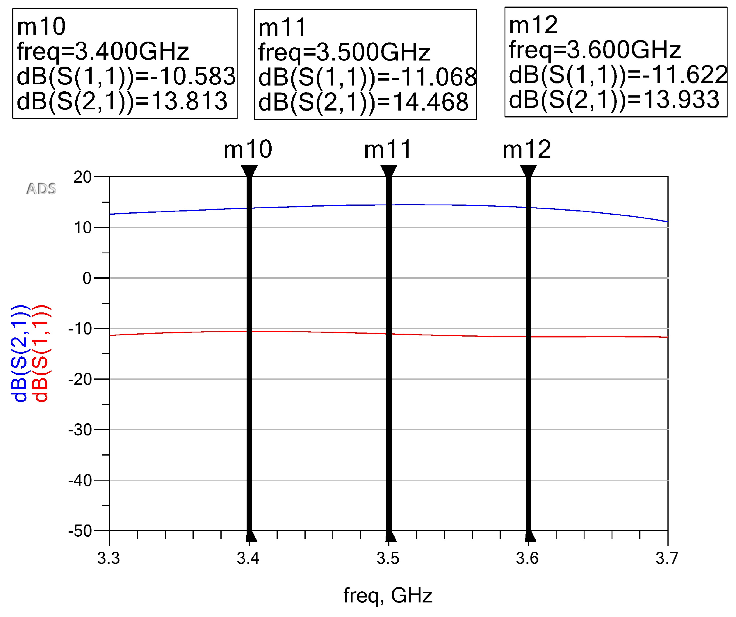
Based on the schematic of PA, the design performs S-parameter simulation. As shown in Figure 3, the measured S11 and S21 at 3.5 GHz are −11.068 dB and 14.468 dB, respectively.
Based on the schematic of PA, the design performs large-signal simulations over the pre-designed band. Figure 4a shows that the small-signal gain at 3.5 GHz is 14.43 dB when the output power is 14.63 dBm, and the gain is 10.14 dB when the output power is 47.11 dBm. In Figure 4b, the drain efficiency is 74.895%, where the saturation output power of 47.86 dBm is delivered. At the 8 dB back-off point, i.e., the output power equals 39.93 dBm, the drain efficiency is still 51.29%.
As shown in Figure 5, the measured power-added efficiency (PAE) reaches 67.28% at an output power of 47.11 dBm.
The efficiency, PAE, and S-parameters of the asymmetric Doherty PA designed in this paper meet the requirements of engineering applications.

4. The Improved Layout and Test

4.1. The Layout Designs

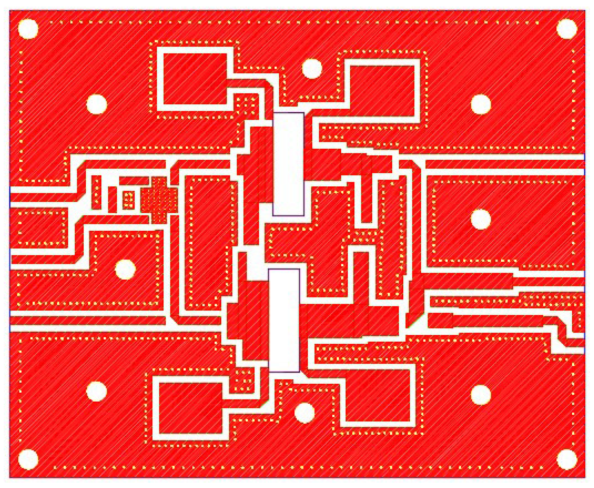
Following the schematic diagram simulation, this paper needs to thoroughly consider package sizes of transistors, isolated capacitors, and other components to operate the layout. According to the traditional layout design method, transistors and the power divider chip are located based on packages of CGHV40030F and CMX35Q05. The grounding holes are evenly distributed around the microstrip line and in the margins of PCB to isolate signals and dissipate heat [34]. The fixing holes for installing the heat dissipation board are distributed in the blank as evenly as possible to keep the heat dissipation board attached to the PCB hardly. To facilitate the subsequent tests, four flying wires are reserved and installed at the input ports and output ports of the main and auxiliary amplifiers, respectively. The layout of the PA circuit is shown in Figure 6.
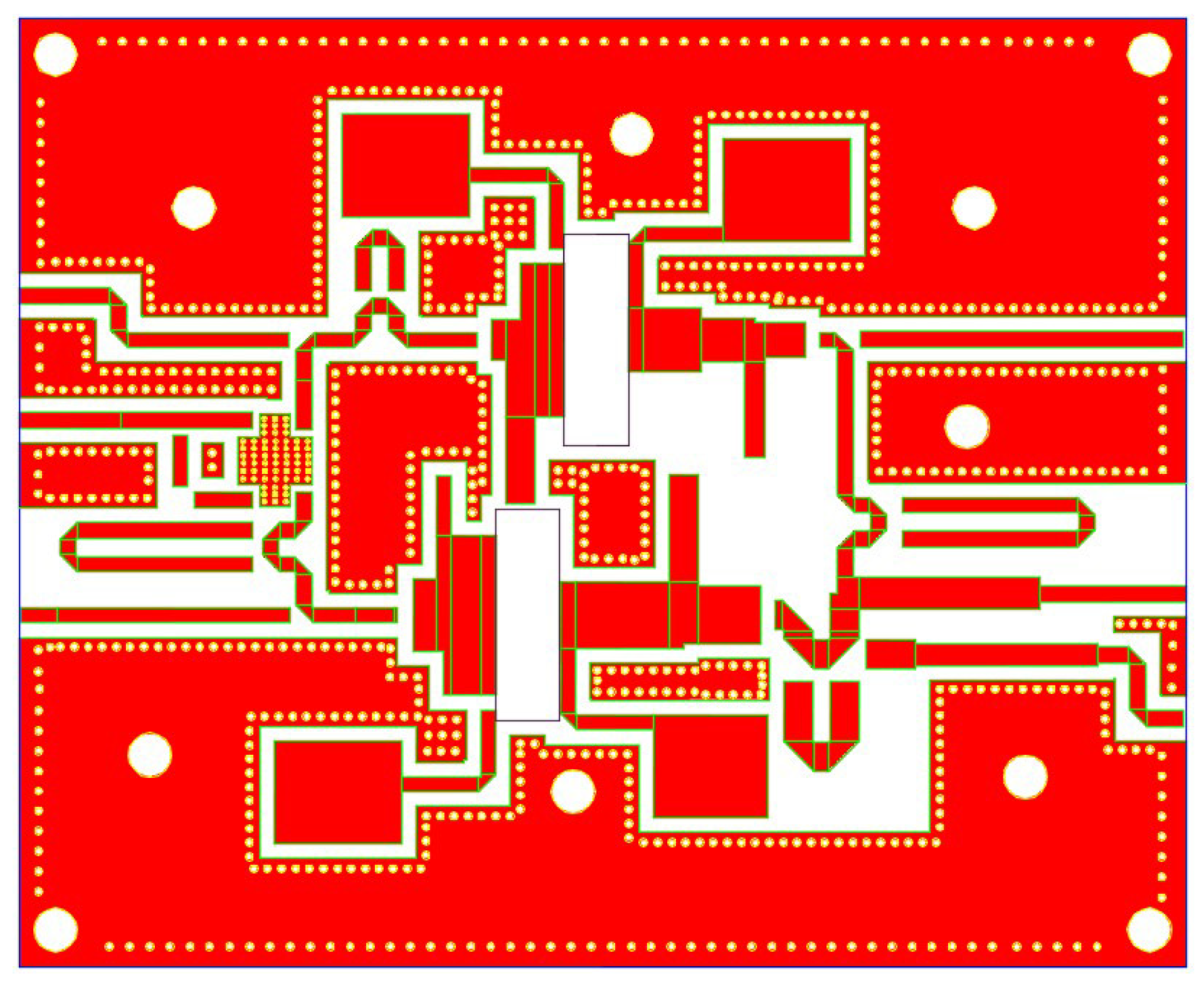
To increase the fault tolerance of the layout, this paper proposes an extended compatibility circuit layout design method. The design proposes a U-shaped microstrip line structure which is capable of fine-tuning the impedance matching network and provides a circuit layout supporting the independent multi-stage debugging. In traditional layouts, the geometric structure of microstrip lines is fixed, making it impossible to adjust the impedance matching network. The unavoidable fabrication variation leads to deviations between actual circuit performance and simulations.The U-shaped microstrip line, as a tunable impedance matching network, leverages its excellent geometric flexibility during debugging. It dynamically addresses impedance mismatch issues at different frequencies or power levels, significantly expanding the circuit’s tuning range and reducing the gap between actual and simulated performance. To enhance debugging efficiency and accelerate fault localization, an independent multi-stage debugging strategy is adopted into the circuit layout. This approach, combined with the U-shaped microstrip line, enables modularized analyses and precise parameter optimization. As a result, the actual circuit can achieve near-optimal performance in a shorter time. The improved layout, which aims to improve the compatibility of input and output offset lines, is shown in Figure 7.

4.1.1. Redundant U-Shaped Microstrip Line Tuning Technique

The U-shaped microstrip lines at the front ends of two transistors are used to compensate for the 90° inherent phase difference of the asymmetric coupler CMX35Q05, ensuring phase coherence between the main and auxiliary branches. The U-shaped microstrip lines behind the main amplifier are used to change the offset line to match perfectly the output circuit. The U-shaped microstrip lines at the terminal of the auxiliary amplifier, which are equivalent to distributed LC resonant networks, could passively suppress the secondary reflection of the main amplifier’s leakage signal. Compared to traditional isolators or circulators, the U-shaped microstrip lines achieve leakage suppression passively, thereby improving PA efficiency. During debugging, the redundant U-shaped microstrip lines can be adjusted to meet different impedance requirements, reducing the gap between actual circuit and simulations.

4.1.2. The Multi-Stage Debugging Strategy

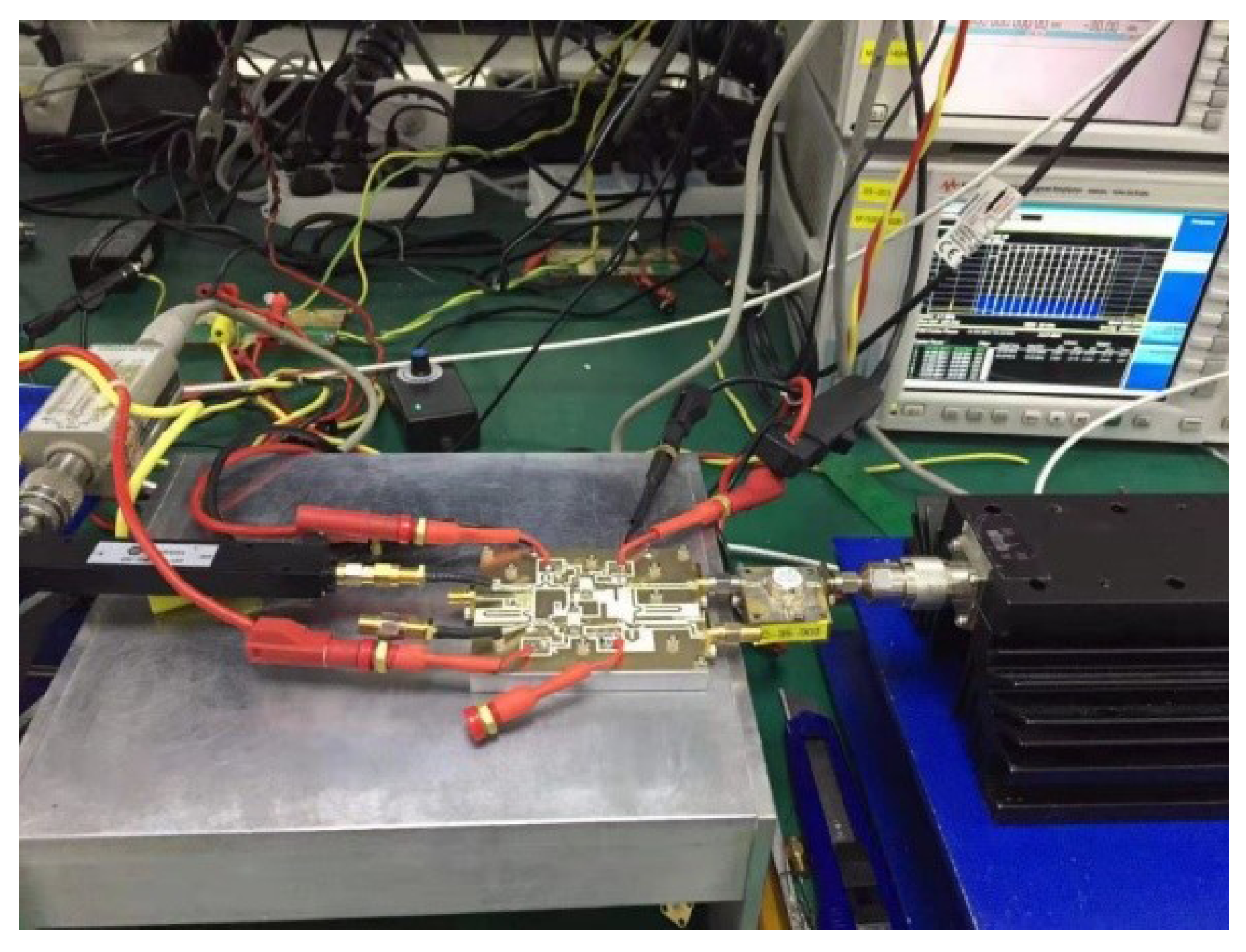
In the design of the asymmetric Doherty power amplifier, an independent multi-step debugging strategy is used to optimize the main and auxiliary amplifiers individually and in combination, result in a significant enhancement of design efficiency and performance reliability. The first step is debugging the main amplifier. By adjusting the input matching circuit to optimize the parameters of standing wave, the main amplifier operates in class AB. By tuning the output matching network, the efficiency and the output power are boosted. The targets are a saturated efficiency of over 60% and an output power error of less than 0.5 dB. The second step is to perform high-impedance debugging for the main amplifier. By disconnecting the auxiliary amplifier, the test from the main amplifier’s input to the end of the λ / 4 microstrip line after the combiner is performed to verify the load-modulation effect. The increase of the saturated efficiency should be 2%, and the drop of output power should be no more than 2 dB. Adjusting the compensation line length is used to prioritize efficiency in the design. The third step is debugging the auxiliary amplifier independently. Given the differences in the asymmetric structure, the auxiliary amplifier’s matching circuit is optimized individually to meet the stand-wave parameters and efficiency requirements in class AB. The fourth step is to debug with the connection of auxiliary amplifier. By connecting the auxiliary amplifier’s output to the combiner point and inserting a 50 Ω terminator to the input, the cut-off state is simulated. The verify that the main amplifier’s performance is not disturbed ensures that there is no hidden load disturbance in the auxiliary amplifier circuit. The fifth step is debugging the entire combined circuit. The main and auxiliary amplifiers are connected fully and the lengths of input compensation lines are calibrated to eliminate phase offset. Fine-tuning the output matching network and gate bias is to enhance both efficiency and linearity performance. As shown in Figure 8, the main amplifier is being debugged.

4.1.3. Circuit Implementation Based on U-Shaped Microstrip Lines and Independent Multi-Stage Debugging Strategy

The chips, capacitances, and connectors are built on the PCB based on the Rogers4350B material, as shown in Figure 9. As mentioned, this design enables dynamic optimization of circuit parameters through redundant multi-segment U-shaped microstrip line arrangements in the layout. Independent input/output interfaces are integrated for both main and auxiliary amplifier paths to support multi-stage debugging strategy. The reconfigurable structure allows engineers to correct PCB-level impedance mismatch using the feedback from a real-time vector network analyzer. This ensures stable operation of power amplifiers within the predefined Class AB/C hybrid biasing range. Experimental results show reduced deviations between measured and simulated efficiencies. The saturated drain efficiency discrepancy is decreased to 1.85%, and back-off efficiency gap is narrowed to 7.38%. The modularized debugging approach enhances fault localization speed and effectiveness of optimizing circuit. The improved design increases the compatibility and tunability of the practical circuit, which is always in a dynamic state. Therefore, the gap between simulations and practices is narrowed, and the transistors can work in the pre-designed state.

4.2. Tests

4.2.1. Efficiency Test

Figure 10 presents the large-signal test environment of the device under test (DUT). According to the direct current (DC) scanning results, two DC power supplies provide the specific voltages to the gates and drains of transistors. The RF signal source is delivered to the input, and the output terminal is connected to the attenuator, followed by a spectrum analyzer.
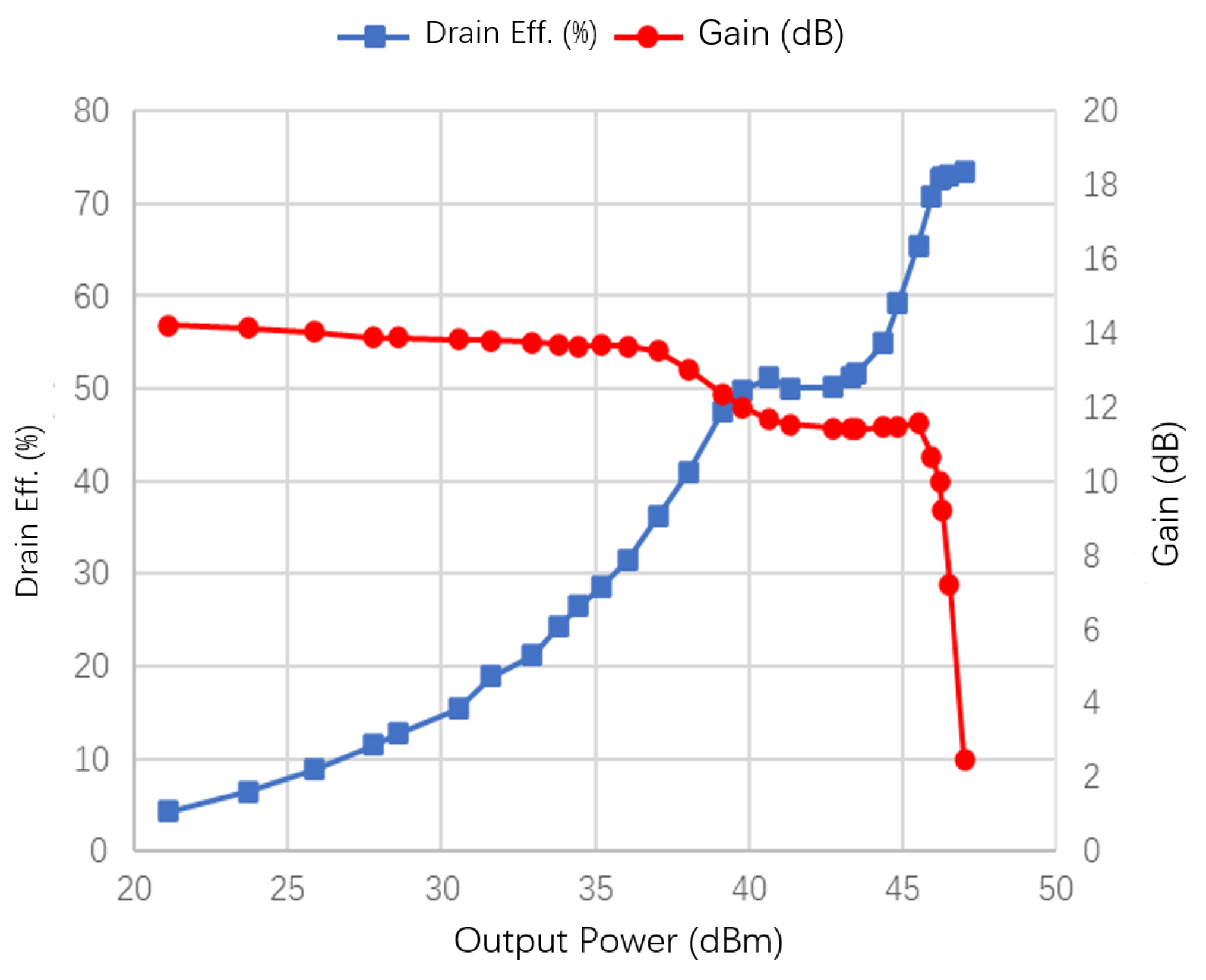
At 3.5 GHz of interest, S-parameter simulations are performed, S11 is −10.73 dB and S21 is 13.83 dB. The large-signal test curves of the PA after debugging and optimizing are shown in Figure 11, which presents the drain efficiency and the gain versus the output power, respectively, in the optimal working state. When the input power ratio of the main amplifier to the auxiliary amplifier is 1:1.5, the saturation output power is 47.02 dBm, and the saturation drain efficiency is 73.5%, the gain of 9.88 dB, and the PAE is 63.74%. At the 8 dB back-off point, i.e., the output power equals 39 dBm, the drain efficiency is 47.5%. These results meet the design specifications of the PA for 5G applications.
Due to voltage losses, machining errors, and parasitic effects of discrete components in the practical circuit, the output power and drain efficiency at the frequency of interest are slightly deteriorated compared with simulations, as shown in Table 1. Compared to simulations, the saturation output power tested in practice is 0.84 dB lower. The drain efficiency is only 1.39% lower at the saturation state and 3.79% lower at 8 dB back-off. Such a slight difference between practices and simulations, thanks to the compatibility design method of the layout. The practical tests are very close to simulations, demonstrating the technique’s effectiveness.

4.2.2. Linearity Test

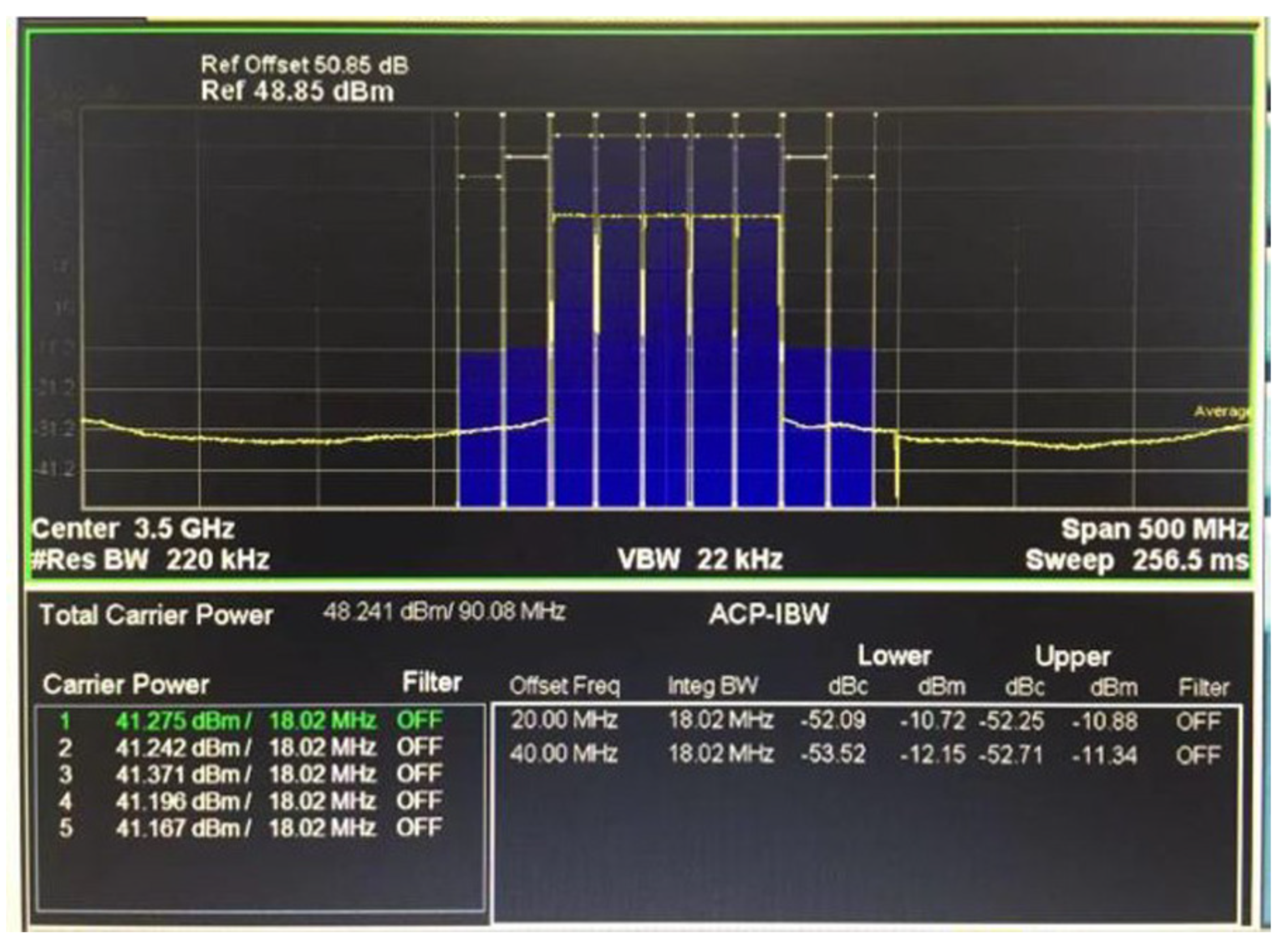
To meet the stringent linearity requirements of wireless communication systems, the designed PA is calibrated using DPD module. As shown in Figure 12, following DPD calibration, the measured power levels at 20 MHz offsets from the lower and upper band edges of the designed frequency range are −52.09 dB and −52.25 dB, respectively. The adjacent channel power ratio (ACPR) meets the engineering design specifications, confirming compliance with linearity performance targets.
The comparisons between the test of our work and the relevant research published in recent years are shown in Table 2. Compared with the literature [35], this paper provides higher output saturation power and better saturation drain efficiency at the same working frequency band. Compared with the literature [36], this paper provides higher output saturation power and better saturation drain efficiency at the same working frequency band. Compared with the literature [37], this paper has higher saturation and back-off efficiency under the same back-off amount.

5. Conclusions

This paper designs a high-efficiency PA with the asymmetric Doherty architecture based on analyzing the principles of the Doherty PA. Different input powers are supplied to the carrier amplifier and the peaking amplifier by the power divider with an unequal power ratio. Two transistors work in class AB and class C, respectively. We utilize the source and load pull to obtain the optimal source and load impedances, respectively. Therefore, the corresponding source matching networks and load matching networks are designed. We utilize four offset lines to increase the output power at the summing node. Schematic simulations show that S11 is −11.09 dB, the saturation drain efficiency is 74.89%, the back-off efficiency is 51.29%, and the PAE is 67.28%. Considering intrinsic errors of the practical circuit, a novel circuit compatibility design method was proposed to maintain dynamic adjustability of the layout. By utilizing an independent multi-stage debugging strategy and adjusting redundant U-shaped microstrip lines, the gap between hardware implementation and simulations is directly reduced during debugging on the PCB, thereby enhancing PA performance. In experimental tests, S11 is −10.73 dB, the saturation drain efficiency is 73.5%, the back-off efficiency is 47.5%, and the PAE is 63.74%. These results demonstrate that the debugged practical circuit is close to the pre-design circuit. To the best of authors’ knowledge, the performance of Doherty PA, designed in this paper, meets the requirements of RFPA for 5G base station applications.

Author Contributions

Conceptualization, M.X. and W.Z.; methodology, M.X. and W.Z.; software, M.X. and W.Z.; validation, M.X. and W.Z.; formal analysis, M.X. and W.Z.; investigation, W.Z.; resources, M.X.; data curation, M.X. and W.Z.; writing—original draft preparation, M.X.; writing—review and editing, M.X. and W.Z.; visualization, M.X. and W.Z.; supervision, M.X.; project administration, M.X. All authors have read and agreed to the published version of the manuscript.

Funding

This research received no external funding.

Data Availability Statement

The original contributions presented in this study are included in the article. Further inquiries can be directed to the corresponding author.

Conflicts of Interest

The authors declare no conflicts of interest.

References

  1. Özen, M.; Andersson, K.; Fager, C. Symmetrical Doherty Power Amplifier with Extended Efficiency Range. IEEE Trans. Microw. Theory Tech. 2016, 64, 1273–1284. [Google Scholar] [CrossRef]
  2. Jia, P.; You, F.; He, S. A 1.8–3.4-GHz Bandwidth-Improved Reconfigurable Mode Doherty Power Amplifier Utilizing Switches. IEEE Microw. Wirel. Compon. Lett. 2020, 30, 102–105. [Google Scholar] [CrossRef]
  3. Ruhul Hasin, M.; Kitchen, J. Exploiting Phase for Extended Efficiency Range in Symmetrical Doherty Power Amplifiers. IEEE Trans. Microw. Theory Tech. 2019, 67, 3455–3463. [Google Scholar] [CrossRef]
  4. Hallberg, W.; Özen, M.; Gustafsson, D.; Buisman, K.; Fager, C. A Doherty Power Amplifier Design Method for Improved Efficiency and Linearity. IEEE Trans. Microw. Theory Tech. 2016, 64, 4491–4504. [Google Scholar] [CrossRef]
  5. Honda, S.; Sakata, S.; Komatsuzaki, Y.; Shinjo, S. Efficiency Enhancement of GaN Doherty Power Amplifier at Large Power Back-Off with Virtual Short Stub Technique. In Proceedings of the 2019 IEEE Asia-Pacific Microwave Conference (APMC), Singapore, 10–13 December 2019; pp. 294–296. [Google Scholar] [CrossRef]
  6. Liang, C.; Roblin, P.; Hahn, Y.; Xiao, Y. Automatic Algorithm for the Direct Design of Asymmetric Doherty Power Amplifiers. In Proceedings of the 2019 IEEE Topical Conference on RF/Microwave Power Amplifiers for Radio and Wireless Applications (PAWR), Orlando, FL, USA, 20–23 January 2019; pp. 1–4. [Google Scholar] [CrossRef]
  7. Mengozzi, M.; Gibiino, G.P.; Angelotti, A.M.; Santarelli, A.; Florian, C.; Colantonio, P. Automatic Optimization of Input Split and Bias Voltage in Digitally Controlled Dual-Input Doherty RF PAs. Energies 2022, 15, 4892. [Google Scholar] [CrossRef]
  8. Grams, V.; Seidel, A.; Stärke, P.; Wagner, J.; Ellinger, F. Analysis and Design of an Asymmetric Doherty Power Amplifier at 2.6 GHz using GaAs pHEMTs. In Proceedings of the 2019 IEEE International Conference on Microwaves, Antennas, Communications and Electronic Systems (COMCAS), Tel-Aviv, Israel, 4–6 November 2019; pp. 1–3. [Google Scholar] [CrossRef]
  9. Asbeck, P.; Popovic, Z. ET Comes of Age: Envelope Tracking for Higher-Efficiency Power Amplifiers. IEEE Microw. Mag. 2016, 17, 16–25. [Google Scholar] [CrossRef]
  10. Masood, M.; Srinidhi, E.R.; Rashev, P.; Holt, J.; Kenney, J.S. 300 W Dual Path GaN Doherty Power Amplifier with 65% Efficiency for Cellular Infrastructure Applications. In Proceedings of the 2020 IEEE/MTT-S International Microwave Symposium (IMS), Los Angeles, CA, USA, 4–6 August 2020; pp. 715–718. [Google Scholar] [CrossRef]
  11. Fang, X.H.; Liu, H.Y.; Cheng, K.K.M. Extended Efficiency Range, Equal-Cell Doherty Amplifier Design Using Explicit Circuit Model. IEEE Microw. Wirel. Compon. Lett. 2017, 27, 497–499. [Google Scholar] [CrossRef]
  12. R, S.E.; McLaren, R.; Masood, M. High Power 400 W Symmetric Doherty with Extended Back-off Efficiency Range for 5G Cellular Infrastructure Applications. In Proceedings of the 2020 50th European Microwave Conference (EuMC), Utrecht, The Netherlands, 12–14 January 2021; pp. 300–303. [Google Scholar] [CrossRef]
  13. Saad, P.; Hou, R.; Hellberg, R.; Berglund, B. A 1.8–3.8-GHz Power Amplifier with 40% Efficiency at 8-dB Power Back-Off. IEEE Trans. Microw. Theory Tech. 2018, 66, 4870–4882. [Google Scholar] [CrossRef]
  14. Shen, C.; He, S.; Zhu, X.; Peng, J.; Cao, T. A 3.3–4.3-GHz High-Efficiency Broadband Doherty Power Amplifier. IEEE Microw. Wirel. Compon. Lett. 2020, 30, 1081–1084. [Google Scholar] [CrossRef]
  15. Bhardwaj, S.; Kitchen, J. Broadband Parallel Doherty Power Amplifier in GaN for 5G Applications. In Proceedings of the 2019 IEEE Topical Conference on RF/Microwave Power Amplifiers for Radio and Wireless Applications (PAWR), Orlando, FL, USA, 20–23 January 2019; pp. 1–3. [Google Scholar] [CrossRef]
  16. Qi, L.; Yin, H.; Chen, P.; Cai, J.; Zhu, X.W.; Yu, C.; Hong, W. Multi-Section Support Vector Regression-Based Behavioral Modeling of RF GaN Doherty Power Amplifiers. In Proceedings of the 2021 IEEE MTT-S International Wireless Symposium (IWS), Nanjing, China, 23–26 May 2021; pp. 1–3. [Google Scholar] [CrossRef]
  17. Pednekar, P.H.; Hallberg, W.; Fager, C.; Barton, T.W. Analysis and Design of a Doherty-like RF-Input Load Modulated Balanced Amplifier. IEEE Trans. Microw. Theory Tech. 2018, 66, 5322–5335. [Google Scholar] [CrossRef]
  18. Wong, J.; Watanabe, N.; Grebennikov, A. High-power high-efficiency broadband GaN HEMT Doherty amplifiers for base station applications. In Proceedings of the 2018 IEEE Topical Conference on RF/Microwave Power Amplifiers for Radio and Wireless Applications (PAWR), Anaheim, CA, USA, 14–17 January 2018; pp. 16–19. [Google Scholar] [CrossRef]
  19. Yadav, P. Optimizing the Doherty Amplifier: Design of a 3-GHz GaN Doherty Amplifier Achieving 60% Efficiency. IEEE Microw. Mag. 2020, 21, 88–95. [Google Scholar] [CrossRef]
  20. Horiguchi, K.; Ishizaka, S.; Nakayama, M.; Hayashi, R.; Isota, Y.; Takagi, T. Efficiency enhancement of a digital predistortion Doherty amplifier transmitter using a virtual open stub technique. IEICE Trans. Electron. 2007, E90C, 1670–1677. [Google Scholar] [CrossRef]
  21. Iizuka, F.; Ogino, T.; Suzuki, H.; Fukawa, K. High-efficiency Doherty linear amplifier with backoff control for mobile communications. In Proceedings of the 2005 IEEE 61st Vehicular Technology Conference, Stockholm, Sweden, 30 May–1 June 2005; Volume 2, pp. 949–953. [Google Scholar] [CrossRef]
  22. Lopera, J.R.; Mayock, J.; Sun, Q.; Gadringer, M.; Bösch, W.; Leitgeb, E. A 3.5 GHz High Power GaN Hybrid Doherty Power Amplifier with Dynamic Input Power Splitting for Enhanced Power Added Efficiency at Backoff. In Proceedings of the 2021 IEEE Topical Conference on RF/Microwave Power Amplifiers for Radio and Wireless Applications (PAWR), San Diego, CA, USA, 17–20 January 2021; pp. 1–4. [Google Scholar] [CrossRef]
  23. Fager, C.; Hallberg, W.; Özen, M.; Andersson, K.; Buisman, K.; Gustafsson, D. Design of linear and efficient power amplifiers by generalization of the Doherty theory. In Proceedings of the 2017 IEEE Topical Conference on RF/Microwave Power Amplifiers for Radio and Wireless Applications (PAWR), Phoenix, AZ, USA, 15–18 January 2017; pp. 29–32. [Google Scholar] [CrossRef]
  24. Mu, G.; Hayashi, H. Enhancing Power Added Efficiency of Doherty Amplifier by Changing Power Ratio of Carrier Amplifier and Peak Amplifier. In Proceedings of the 2021 3rd International Conference on Computer Communication and the Internet (ICCCI), Nagoya, Japan, 25–27 June 2021; pp. 176–179. [Google Scholar] [CrossRef]
  25. Jang, H.; Roblin, P.; Quindroit, C.; Lin, Y.; Pond, R.D. Asymmetric Doherty Power Amplifier Designed Using Model-Based Nonlinear Embedding. IEEE Trans. Microw. Theory Tech. 2014, 62, 3436–3451. [Google Scholar] [CrossRef]
  26. Xu, X. ADS2011 RF Circuit Design and Dimulation Example; Publishing House of Electronics Industry: Beijing, China, 2014; ISBN 9787121227998. [Google Scholar]
  27. A CREE COMPANY. An Unmatched, Gallium Nitride (GaN) High Electron Mobility Transistor (HEMT) Amplifier. CGHV40030 Datasheet, April 2020. Available online: https://www.digikey.com/htmldatasheets/production/1634290/0/0/1/cghv40030.html (accessed on 1 April 2025).
  28. Zhou, X.Y.; Zheng, S.Y.; Chan, W.S.; Fang, X.; Ho, D. Postmatching Doherty Power Amplifier with Extended Back-Off Range Based on Self-Generated Harmonic Injection. IEEE Trans. Microw. Theory Tech. 2018, 66, 1951–1963. [Google Scholar] [CrossRef]
  29. Cai, L.; Xiao, M.; Chai, R. Design of GPS Receiver Low Noise Amplifier Based on PHEMT. In Proceedings of the 2019 3rd International Conference on Electronic Information Technology and Computer Engineering (EITCE), Xiamen, China, 18–20 October 2019; pp. 838–841. [Google Scholar] [CrossRef]
  30. Choi, W.; Kang, H.; Oh, H.; Hwang, K.C.; Lee, K.Y.; Yang, Y. Doherty Power Amplifier Based on Asymmetric Cells with Complex Combining Load. IEEE Trans. Microw. Theory Tech. 2021, 69, 2336–2344. [Google Scholar] [CrossRef]
  31. Kim, S.; Moon, J.; Lee, J.; Park, Y.; Minn, D.; Kim, B. Accurate Offset Line Design of Doherty Amplifier with Compensation of Peaking Amplifier Phase Variation. IEEE Trans. Microw. Theory Tech. 2016, 64, 3224–3231. [Google Scholar] [CrossRef]
  32. Pang, J.; He, S.; Dai, Z.; Huang, C.; Peng, J.; You, F. Design of a Post-Matching Asymmetric Doherty Power Amplifier for Broadband Applications. IEEE Microw. Wirel. Compon. Lett. 2015, 26, 52–54. [Google Scholar] [CrossRef]
  33. Kato, T.; Yamaguchi, K.; Kuriyama, Y.; Yoshida, H. A 4-mm-Square Miniaturized Doherty Power Amplifier Module for W-CDMA Mobile Terminals. IEICE Trans. Fundam. Electron. Commun. Comput. Sci. 2007, E90-A, 310–316. [Google Scholar] [CrossRef]
  34. Horiguchi, K.; Matsunaga, N.; Yamauchi, K.; Hayashi, R.; Miyazaki, M.; Nojima, T. A Wideband Digital Predistorter for a Doherty Power Amplifier Using a Direct Learning Memory Effect Filter. IEICE Trans. Electron. 2010, E93.C, 975–982. [Google Scholar] [CrossRef]
  35. Guo, P.; Kong, W.; Xia, J.; Yang, L. Wideband Doherty power amplifier using suitable peaking output matching network. In Proceedings of the 2015 Asia-Pacific Microwave Conference (APMC), Nanjing, China, 6–9 December 2015; Volume 1, pp. 1–3. [Google Scholar] [CrossRef]
  36. Hone, T.M.; Bensmida, S.; Morris, K.A.; Beach, M.A.; McGeehan, J.P.; Lees, J.; Benedikt, J.; Tasker, P.J. Controlling Active Load–Pull in a Dual-Input Inverse Load Modulated Doherty Architecture. IEEE Trans. Microw. Theory Tech. 2012, 60, 1797–1804. [Google Scholar] [CrossRef]
  37. Xiong, H.; Chen, W.; Chen, L.; Chen, X.; Feng, Z. A High Efficiency Asymmetric Doherty Power Amplifier Using Symmetric Devices for 5G Application. In Proceedings of the 2018 International Conference on Microwave and Millimeter Wave Technology (ICMMT), Chengdu, China, 7–11 May 2018; pp. 1–3. [Google Scholar] [CrossRef]
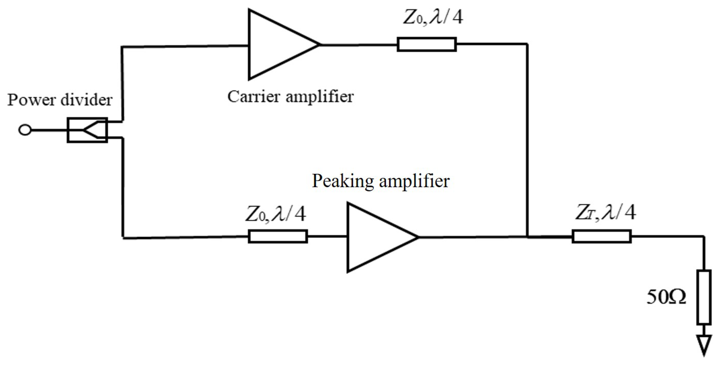
Figure 1. The classical architecture of the symmetric Doherty PA.
Electronics 14 01586 g001
Figure 2. The offset lines utilized in an asymmetric Doherty PA.
Electronics 14 01586 g002
Figure 3. The S−parameter simulation.
Electronics 14 01586 g003
Figure 4. Large−signal simulations. (a) The gain versus the output power. (b) The drain efficiency versus output power.
Electronics 14 01586 g004
Figure 5. PAE versus Output Power.
Electronics 14 01586 g005
Figure 6. The layout of PA circuit with the traditional method.
Electronics 14 01586 g006
Figure 7. The improved layout of PA circuit with the compatibility method.
Electronics 14 01586 g007
Figure 8. Standalone Tuning of the Main Amplifier.
Electronics 14 01586 g008
Figure 9. The photo of the high-efficiency PA.
Electronics 14 01586 g009
Figure 10. The photo of the large-signal test.
Electronics 14 01586 g010
Figure 11. The drain efficiency and the gain versus the output power at 3.5 GHz.
Electronics 14 01586 g011
Figure 12. ACPR−measurement Results.
Electronics 14 01586 g012
Table 1. Comparison of performance indicators between simulations and measurements at 3.5 GHz.
Index P sat (dBm)DE@ P sat (%)DE@OBO (%)PAE@ P sat (%)S11 (dB)S21 (dB)
Simulations47.8674.8951.2967.28−11.0714.47
Tests47.0273.5047.5063.72−10.7313.83
Table 2. Comparisons with the reported ADPAs.
Ref.Frequency (GHz) P sat (dBm)DE@ P sat (%)DE@OBO (%)
[34]3.4–3.645.5–4665–6842–44@9 dB
[35]2.7–2.943.864.943@9 dB
[36]3.4–3.6476241@8 dB
T.W.3.547.0273.547.5@8 dB
Disclaimer/Publisher’s Note: The statements, opinions and data contained in all publications are solely those of the individual author(s) and contributor(s) and not of MDPI and/or the editor(s). MDPI and/or the editor(s) disclaim responsibility for any injury to people or property resulting from any ideas, methods, instructions or products referred to in the content.