Article

Methodology and Challenges of Implementing Advanced Technological Solutions in Small and Medium Shipyards: The Case Study of the Mari4_YARD Project

by
Lorenzo Grazi
1,*,
Abel Feijoo Alonso
2,†,
Adam Gąsiorek
3,†,
Afra Maria Pertusa Llopis
2,†,
Alejandro Grajeda
2,†,
Alexandros Kanakis
4,†,
Ana Rodriguez Vidal
2,†,
Andrea Parri
5,†,
Felix Vidal
2,†,
Ioannis Ergas
6,†,
Ivana Zeljkovic
7,†,
Javier Pamies Durá
8,†,
Javier Perez Mein
9,†,
Konstantinos Katsampiris-Salgado
4,†,
Luís F. Rocha
10,†,
Lorena Núñez Rodriguez
9,†,
Marcelo R. Petry
10,†,
Michal Neufeld
3,†,
Nikos Dimitropoulos
4,†,
Nina Köster
11,†,
Ratko Mimica
7,†,
Sara Varão Fernandes
12,†,
Simona Crea
1,†,
Sotiris Makris
4,†,
Stavros Giartzas
4,†,
Vincent Settler
11,† and
Jawad Masood
2,*
add Show full author list remove Hide full author list
1
The BioRobotics Institute, Scuola Superiore Sant’Anna, 56127 Pisa, Italy
2
Smart Systems and Smart Manufacturing Group, AIMEN Technology Centre, 36410 Pontevedra, Spain
3
Transition Technologies PSC SA, 90-530 Łódź, Poland
4
Laboratory for Manufacturing Systems & Automation, University of Patras, 26504 Rion Patras, Greece
5
IUVO S.r.l., 56025 Pontedera, Italy
6
Foundation WEGEMT–A European Association of Universities in Marine Technology and Related Sciences, Mekelweg-Faculteit MT 2, 2628 CD Delft, The Netherlands
7
Brodosplit, 21000 Split, Croatia
8
GHENOVA Ingenieria, 36201 Vigo, Spain
9
NODOSA SL, 36900 Marín, Spain
10
INESC TEC — Institute for Systems and Computer Engineering Technology and Science, 4200-465 Porto, Portugal
11
Institute of Production Management and Technology, Hamburg University of Technology, 21073 Hamburg, Germany
12
European Federation for Welding, Joining and Cutting, 2740-119 Porto Salvo, Portugal
*
Authors to whom correspondence should be addressed.
These authors contributed equally to this work.
Electronics 2025, 14(8), 1597; https://doi.org/10.3390/electronics14081597
Submission received: 7 February 2025 / Revised: 1 April 2025 / Accepted: 4 April 2025 / Published: 15 April 2025

Abstract

:
Small to medium-sized shipyards play a crucial role in the European naval industry. However, the globalization of technology has increased competition, posing significant challenges to shipyards, particularly in domestic markets for short sea, work, and inland vessels. Many shipyard operations still rely on manual, labor-intensive tasks performed by highly skilled operators. In response, the adoption of new tools is essential to enhance efficiency and competitiveness. This paper presents a methodology for developing a human-centric portfolio of advanced technologies tailored for shipyard environments, covering processes such as shipbuilding, retrofitting, outfitting, and maintenance. The proposed technological solutions, which have achieved high technology readiness levels, include 3D modeling and digitalization, robotics, augmented and virtual reality, and occupational exoskeletons. Key findings from real-scale demonstrations are discussed, along with major development and implementation challenges. Finally, best practices and recommendations are provided to support both technology developers seeking fully tested tools and end users aiming for seamless adoption.

1. Introduction

Small to medium-sized enterprises (SMEs) are the cornerstone of the naval industry, particularly in Europe. The European shipbuilding and ship maintenance, repair, and conversion (SMRC) sector comprises about 300 specialized shipyards, with over 80% being SMEs that build and maintain ships up to 150 m [1,2]. These SMEs are vital for regional employment and play a fundamental role in the European maritime supply chain, which includes over 22,000 enterprises with a turnover of 60 billion euros. The industry’s competitive edge lies in its highly skilled labor force, manufacturing expertise, and regional collaboration networks [3,4]. However, the globalization of technology has enhanced competitor’s capabilities, causing more competition and difficulties for SME shipyards, particularly in their domestic markets for short sea, work, and inland vessels [4].
Ship design and manufacturing are increasingly complex [5,6]. This complexity accounts for 20–25% of total costs. The need for seamless integration between design and manufacturing processes exacerbates these challenges. Limited production efficiency and product quality are major issues for SME shipyards, often because tolerances, deformations, and large structures lead to frequent reconfigurations and reworks [7]. Manufacturing equipment is often cumbersome, costly, and rigid. This makes it hard for SMEs to invest in flexible, modular solutions, especially for low-volume production. The manual, labor-intensive nature of shipbuilding, combined with increasing complexity and high-skill requirements, further complicates the shipbuilding process [8]. Skilled workers are scarce, while supply chain integration is poor, causing delays and waste. Additionally, the low production volumes make automation investment hard to justify, hindering the attraction of investment and skilled personnel.
To address these issues, the Mari4_YARD project (https://www.mari4yard.eu/, accessed on 6 February 2025) explored the deployment of human-centric technologies and the establishment of a systematic infrastructure for upskilling the existing workforce. The relevance of this work is well-founded, as the EU has funded multiple initiatives to support the development and implementation of innovative technological solutions in the maritime sector. Examples of EU-funded research programmes are the PeneloPe (https://penelope-project.eu/, accessed on 26 March 2025) and MATES (https://www.projectmates.eu/, accessed on 26 March 2025) projects. This paper presents a novel methodology for approaching the development and implementation of technological solutions within SME shipyards. In the literature, several initiatives have aimed to develop methodologies for the shipbuilding sector [9,10,11]. For example, the methodology outlined in [10] benefits shipyards by aligning technology adoption with strategic goals, thereby enhancing efficiency and competitiveness; however, its dependence on extensive case data may restrict its practical applicability for small and medium shipyards with limited resources. In contrast, the AHP based approach [11] improves decision-making and productivity through structured prioritization for the same set of technologies; however, its implementation for higher technology readiness levels (TRL) development for a versatile set of technologies at small and medium shipyards is limited. On the contrary, the Mari4_YARD iterative development methodology and the application of a didactic factories network to upskill the shipbuilding workforce are demonstrated through selected results from four technological blocks (TRL 6–7) at SME shipyards. The technical development detailed results are outside the scope of this paper.
The implementation of human-centric technologies is crucial for the digital transformation of the shipbuilding industry [12,13], increasing operational efficiency, reducing costs, improving sustainability, and enhancing safety [14,15]. Key technologies include 3D modeling and digitalization, robotics, augmented/mixed reality (AR/MR), and AI-supported occupational exoskeletons (OE).
  • 3D Modeling and Digitalization. Through digital twin (DT) technology, process digitalization enables the creation of digital replicas of entire vessels or specific components, allowing for real-time monitoring, predictive maintenance, and performance optimization [16,17]. This technology is particularly relevant for modeling and simulating complex shipbuilding processes and systems. Traditional stand-alone simulations are inadequate due to continuous environmental changes or lack of CAD models [7,18].
  • Robotics. Originating during the third industrial revolution, robotics has become more flexible and autonomous [7,19], thus aligning with the shift from mass to customized production. In shipbuilding, robotic tools automate welding, assembly, and logistic operations [15,20,21], reducing manual and dangerous labor while enhancing productivity. Advanced sensors have given rise to collaborative robots (cobots), enabling human operators work closely with robotic devices [22]. However, the precise robot localization in the harsh shipyard environment is still a major challenge [23].
  • Augmented and Mixed Reality (AR/MR). AR/MR has become a valuable tool in manufacturing, enabling workers to collaborate effectively, access real-time information, and monitor and control systems interactively [24,25,26]. AR fully immerses operators in a virtual world for training and knowledge improvement. Meanwhile, MR merges the real and virtual worlds, providing virtual data and information where and when needed [7]. Precise localization of the virtual and augmented information using projection and wearable devices is still a challenge due to the harsh shipbuilding environment.
  • Occupational Exoskeletons (OE). A key driver of Industry 4.0, AI-supported occupational exoskeletons can significantly support shipbuilding processes [25]. These active exoskeletons, equipped with onboard sensors, adapt to user needs by providing corresponding force and torque through actuators [27,28]. AI classifiers and algorithms work intelligently, adapting to user physiological requirements and reducing physical strain and fatigue-induced errors.
This paper is organized as follows: First, the methodology of technology development is presented, including the iterative design approach, demonstration design, functional requirements analysis, key performance indicators, and cost-benefit analysis. Next, the results of the demonstrations are presented, along with the role of didactic factories. Finally, challenges to the introduction of these human-centric technologies as well as recommendations for possible future research are discussed.

2. Mari4_YARD Methodology

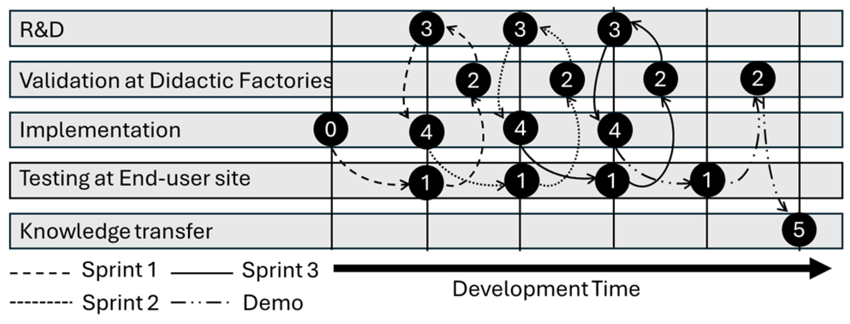
2.1. Iterative Approach

To support the deployment of the Mari4_YARD approach and meet the project’s objectives, a dual strategy was proposed: a technology-driven methodology and a barrier-driven methodology. This double approach enabled the independent development of the technologies portfolio, ensuring a wide replication potential in the EU shipbuilding sector beyond the two end users involved in the project.
The technology-driven methodology, as shown in Figure 1, involved a structured approach to develop and test the Mari4_YARD technologies. The process began with the end users defining their demonstrator requirements. These requirements guided the expansion of Mari4_YARD technologies. The goal was to meet the needs of the shipbuilding sector and SME shipyards. The development of technologies and capabilities to address SME shipyards’ needs was a key step, followed by the assembly and configuration of the developed technologies portfolio. Integration with existing digital tools in the shipyard was also crucial to ensure interoperability and connectivity. A series of test sprints and intermediate evaluations allowed the validation and ramp-up of the technologies. This process included preparation, setup, testing, and evaluation stages. The final demonstration and benchmarking of the worker-centric tools in novel shipbuilding and retrofitting/repairing applications completed the technology-driven methodology. This was the main focus of this paper.
In parallel to the technical tasks, the barrier-driven methodology addressed the market limiting factors to adopt the Mari4_YARD approach. This approach involved several activities, including testing and assessing developed technologies (three test sprints), and implementing them in facilities of research and technology organizations (RTOs) to establish Mari4_YARD didactic factories and general-purpose showrooms. The Mari4_YARD didactic factories offered in situ training courses to shipbuilding SMEs. This helped bridge gaps in skills related to digital and novel technologies [29,30]. Additionally, efforts aimed to harmonize the developed technologies with different digital solutions and shipyard management systems. They also focused on generating, identifying, and protecting IP within individual and integrated exploitation strategies. Finally, dissemination and communication activities aimed to promote the technology portfolio to wider audiences, guaranteeing stakeholder engagement and community building.

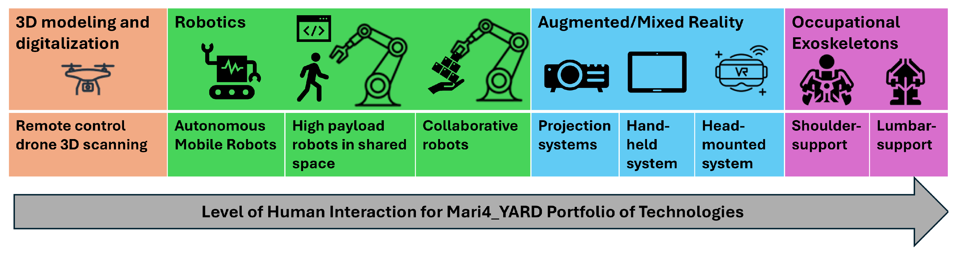
2.2. Portfolio of Technologies

The technological solutions developed in the Mari4_YARD project can be categorized into four main classes: (1) 3D modeling and digitalization, (2) robotics with multi-layer safety systems, (3) augmented reality for on-site support, and (4) occupational exoskeletons for physical assistance at naval construction sites (Figure 2). These technological solutions have been designed and developed following a user-centered approach. This approach prioritized the needs, preferences, and experiences of small and medium shipyards [31]. In the following subsections, each technological category is explained. It presents each system’s specifications, methods used, and main limitations observed at SME shipyards.

2.2.1. 3D Modeling and Digitalization

Drones to perform 3D Scanning. The 3D scanning system (Figure 3a) used the drone DJI Matrice 300 RTK™, customized with the Zenmuse L1™ vision system. It included a LiDAR, IMU, stabilizer, and RGB camera, which had primarily functioned to color the point cloud. The drone required accessories to increase geopositioning precision (including an RTK station, namely a ground-based device that improves the accuracy of GPS signals, such as the DJI D-RTK 2). It also included a parachute for urban missions to improve safety. The DJI Terra™ software (v3.7.0) processed the data, which were stored on a 256 GB micro-SD card. The scans were processed to form point clouds or 3D models. This enabled comparisons between daily scans, with key capabilities including importing standard CAD models into NAVISWORKS™ software (v20.3). This aided in locating elements with precision, measuring distances and areas, and exploring the global model in a 3D environment. Meanwhile, flight permissions were obtained in compliance with legal requirements for flying drones in open areas, such as shipyards. In outdoor environment, GPS for LiDAR-based localization enabled the real-time updates to shipyard production workflows; in indoor settings, it was achieved through simultaneous localization and mapping (SLAM) technology. The primary requirement for this technology is the availability of software licenses. It also had to allow the re-scanning after updates to the shipbuilding facilities, which are typically not very frequent.

2.2.2. Robotics

Autonomous Mobile Robots. The system (Figure 3b) consisted of the following modules: an omnidirectional mobile robotic platform, endowed with two LiDAR sensors (Sick 3000) installed at different opposite corners; a robotic arm (UR10), mounted on top of the mobile platform, equipped with a 3D sensing device (Photoneo PhoXi S 3D Scanner) and two grasping tools (Robotiq 2 Finger Gripper and a OnRobot MG10 Magnetic Gripper). The robot included software for autonomy and control. This enabled the robot to navigate in confined and cluttered spaces [32] and pick non-standardized parts [33,34]. It also included tools and methods for human–robot interaction and easy collaboration. The developed technologies were hardware agnostic, allowing for easier deployment on various robot hardware, supporting different needs, and ensuring scalability.
High-Payload Robots in Shared Spaces with Humans. The system (Figure 3c) consisted of the following modules: an industrial robot (COMAU NJ 130) for manipulating heavy loads; a welding torch; a magnetic gripper; a force/torque sensor for hand guiding; laser scanners for safety; and an RGB-D camera for bin picking. All hardware modules were commercially available. Machine vision enabled bin-picking operations, allowing for a CAD-less approach to reaching parts without requiring dataset preparation and training. It also played a role in avoiding collisions during robot navigation and in correcting welding processes. An AR programming suite facilitated tasks such as robot control, welding path programming, and teaching the robot, all without requiring expert knowledge. Additionally, a vision-based method ensured the accuracy of welding paths programmed via the AR interface. To enhance the robot programming suite, a hand-guiding system supported operators positioning parts accurately during assembly. Force feedback was also added at the robot’s wrist and joystick, which controlled ship hull surfaces of varying weights. An incorporated safety monitoring system ensured compliance with safety regulations by protecting operators working close to the robot [35]. It constantly checked the environment and adjusted speed and force if a hazard was detected in the work area.
Collaborative Robots. Collaborative robots provided a compact and lightweight solution for industrial applications [36], capable of supporting adequate payload for welding and cutting tools at the small shipyard. These processes were automated based on the following steps: A 3D sensor detected points of interest and localized them within the robot’s surroundings. Subsequently, by using the obtained data, the robot created a trajectory for movement. This step was implemented within the ROS framework. Robot signals facilitated the communication with the plasma cut machine, while a ModBUS TCP-IP server controlled the welding machine. For the cutting operation, a CAD file was required to localize the robot within the space using point-cloud processing tools, helping find the exact cutting position for the robot. Additionally, a human–machine interface (HMI) defined and configured welding trajectory points, allowing for the setting of welding parameters. To further explore the capabilities of collaborative robots, we investigated the collection of position data from the robot, as well as cutting process parameters, using an ammeter clamp and reading voltage from analog inputs. These data were published to an OPC-UA server and exchanged within the vertical integration architecture via hierarchical data format (hdf5) files. In the human–robot collaboration, we ensured smooth operation in tight spaces by keeping the calibration and configuration process simple by locating and choosing the cutting position. The operator only needed to consider the available space and the robot’s potential movements. Additionally, because the robot is designed to work safely with humans, it could be quickly stopped in case of emergency, ensuring safety. However, we observed several limitations in the implementation of these technologies. Specifically, both the camera and robot systems required an ROS interface to connect and be orchestrated by the system. Moreover, the localization system necessitated a manual initial guess of the robot’s positioning within the space. If a different cut operation was performed at a distance from the previous one, requiring robot movement, the localization had to be recomputed. The robot’s working area also imposed limitations on the length of the welding joint and the cutting height and radius achievable. Lastly, a CAD file was required for the cut operation to localize the robot.

2.2.3. Augmented/Mixed Reality

High-Precision Projection Systems. The high-precision projection solution (Figure 3d) consisted of the following modules: a 3D perception system; a 3D rendering SDK; and a 4K DLP projector to project information directly onto the target object. A movable tripod integrated the projector and 3D sensor for ease of use and to avoid interfering with the operator’s field of view. The system provided an immersive HMI to assist human operators in performing tasks such as marking, cutting, and assembling supply modules during outfitting. It allowed the human operators to perform these tasks faster, more accurately, and with fewer mistakes, without relying on error-prone traditional measuring devices and printed documents. To operate the solution after executing the calibration procedure, the operator needed to open the graphical user interface and perform the loading of the ship section of interest; then, the operator needed to specify the approximate pose of the tripod in relation to the CAD model origin. This six degrees of freedom (DoF) pose given by the operator was used as an initial alignment for the iterative closest point (ICP) algorithm, so it did not need to be very accurate. The precision of the projection relied on the alignment of the ICP algorithm and was dependent on the overlap of the CAD model and the 3D point cloud of the environment. To balance accuracy and computational efficiency, only the geometric information was retained in a point cloud format. This step was necessary because the ship could have subsections with similar geometry and could have limited field of view of the 3D sensor. The operator needed to provide a rough initial pose to allow the 3D perception system to achieve an alignment converging to the correct subsection of the ship. After the 3D perception stage, the system projected the CAD model content onto the environment, as shown in Figure 3d. The impact of the ambient lighting was addressed in two key stages of the projection system: the environment perception stage and the projection stage. In the environment perception stage, a structured light ZIVID sensor was used. This sensor has built-in processing algorithms that reduce noise in the point cloud, even in poor lighting conditions [37]. As a result, more reliable data were obtained despite changes in lighting. In the projection stage, a high-power projector was used. This projector is designed to overpower ambient light, ensuring clear and accurate projections. For tougher conditions, robustness could be improved by switching to laser-based sensors and projectors. These are less affected by variations in ambient lighting.
Cost-Effective Projection Systems. The cost-effective projection system consisted of the following modules [36]: a pan-tilt unit; a projector and a camera; a computer; and a magnet. The pan-tilt unit allowed the system to move freely in two directions, allowing for a range of motion from −66.5° to 66.5° in the tilt axis and from 0° to 306° in the pan axis. This improved the system’s operational capabilities. The system’s components were carefully selected to make the operator’s tasks easier. The projector (EPSON EH-TW 5400) projected supplementary information directly into the real environment, enhancing the user experience and system effectiveness. The camera (Zed 2i) facilitated scanning and monitoring of the working area with high precision and accuracy. The system’s software was executed on a personal computer, managing projection, camera input, and overall system functionality. The system was operated by performing calibration and uploading the CAD of the designated work area. The system then scanned the specified region, compared it with the provided CAD data, and projected onto the actual environment. To evaluate the system’s capabilities, a low-cost projection system was used to recognize a scene at a medium-sized shipyard and project the desired CAD file. The CAD files included recognizable features, such as corners with multiple planes and key elements. The geometric detail was adjusted by setting the voxel size parameter in the user interface. An ICP algorithm enabled localization. The operator provided an initial manual pose to begin the process. The ZED2i camera’s built-in algorithms helped minimize the effects of changing ambient lighting conditions. The system did not operate in real time, meaning that scanning and localization occurred at the start of the process. Afterward, the projected information remained visible until the workers finished the task. The system’s effectiveness was assessed by comparing task performance by the operator with and without the projection aid.
Hand-Held AR devices. This technology (Figure 3f) consisted of two applications: a user-centric tablet application for easily checking construction progress in a designated construction area; and a web application to prepare and provide data for the tablets. It also served as a user interface for a clear evaluation of progress recordings [38]. The developed application operated with almost no latency, facilitated by the high computational power of the tablets used (iPad Pro, Apple). This ensured a nearly seamless interaction experience, enabling effective real-time use. The prepared data in the web application could be entered manually or automatically by third-party systems, such as the shipyard’s PLM systems. The prepared data were then downloaded to the mobile device. Then, the tablet app could be used to navigate the working environment in CAD or AR mode, and helped carry out work processes and check their status. A pipeline to automatically convert the 3D models was developed. This conversion modified metadata but did not cause any visible differences. Since the iPad tablets used powerful hardware and the mobile application was developed in a 3D engine, they could display entire ship sections without noticeable performance loss. The use of a tracking box allowed for localization through image tracking. Additionally, a different approach for tracking with four anchor points was considered, but it was discarded due to the lack of intuitiveness. The tracking box method allowed for fast and sufficiently accurate alignment in a dynamic environment by aligning the physical and virtual boxes on the fly with distinctive geometric reference points. Tracking performance was experimentally tested under varying lighting conditions in a lab environment. The results showed reduced accuracy in extreme lighting conditions, namely in very bright or very dark conditions. However, for the lighting conditions expected in shipyard operations, tracking accuracy remained within acceptable limits. Construction or supervision production progress tasks could be marked as successfully performed; otherwise, issues could be reported with text- and/or image-based documentation. After that, the information could be monitored by supervisors in the web application, so that they could quickly react to status updates from the site. Relevant data could be exported back to the shipyard’s own systems. Thus, the system served as an additional source of information for the workers involved without requiring any dedicated skills. At the time of the experimental verification of the system, it was at a prototype stage, only including standard login security as it ran in an isolated surrounding. Future plans include integration into the shipyard’s existing IT infrastructure, where it will benefit from the security measures already in place.
Head-Mounted AR devices. The system (Figure 3e) consisted of a hands-free, voice-controlled head-mounted device (RealWear Navigator®) securely attached to a safety helmet. Equipped with wireless connectivity, a monocular camera, microphones, and advanced noise cancellation algorithms, the device enables engineers to operate entirely through voice commands, eliminating the need for manual interaction. The device seamlessly integrated with TTPSC SkillWorx™, leveraging computer vision and remote visual SLAM that built sparse 3D point cloud to overlay critical information onto the ship structure and shipyard equipment. Additionally, it tracked frame to frame, generating a local 3D coordinate system from 2D videos. The latency of the system varied based on network conditions and ranged from 50 to 200 ms, which was sufficient to ensure a comfortable user experience with devices like RealWear Navigator® that use opaque micro-displays for glance-based interaction. Users did not need to rely constantly on the micro-display; instead, they engaged with the real world and glanced at the display only when necessary, particularly during critical steps. This allowed them to stay focused on their real-world tasks. The system followed a “say what you see” approach, where the screen showed the most relevant voice commands for the headset wearer. Meanwhile, less-used commands were tucked away in a “show help” menu to keep the screen uncluttered yet accessible. To handle changes in ambient lighting and occlusion, histogram equalization was applied. To ensure cybersecurity, all real-time communications were protected with TLS 1.2/1.3 encryption to prevent unauthorized access. For securing data at rest, the following measures were implemented: only whitelisted devices could connect; collaboration spaces (“rooms”) were password-protected; files downloaded by the head-mounted app from the server were stored in an application sandbox managed by the device’s operating system; web access to resources was further secured with a session key; and links shared with spectators for meetings were temporary and expired once the meeting ended. This paper presents a demonstration of the system in a medium-sized shipyard use case, showcasing how it enhances field engineer’s efficiency while keeping their hands free at all times.

2.2.4. Occupational Exoskeletons

Two OEs—namely, a shoulder support exoskeleton and a lumbar support exoskeleton—were developed (Figure 3g,h). Their ultimate goal was to reduce the physical strain of the workers in the production stages characterized by the presence of work-related movements for the shoulder girdle and the spine [39]. They targeted the reduction in the muscular effort of the assisted muscles [40], namely the anterior deltoid, medial deltoid, and upper trapezius for the shoulder support exoskeleton [41,42,43] and the erector spinae longissimus and iliocostalis for the back support exoskeletons [44,45]. As “wearable” tools, both exoskeletons were designed to provide a comfortable human–machine interaction, due to a light structure and a highly compatible kinematic chain that ensure complete freedom of movement. A set of adjustments ensured the high adaptability of the devices to different body sizes. Both OEs also included a control unit devoted to collecting kinematic information from an integrated sensory apparatus wireless communicating with external IoT networks. Both devices were battery-operated. Power consumption was optimized to ensure a battery life of more than 8 h, i.e., longer than the normal work shift duration.
Shoulder support OE. The shoulder support OE was a semi-active device, designed to provide anti-gravitational support to the user’s arms for those job activities that require static or repetitive shoulder flexion [46,47]. The exoskeleton was capable of automatically adjusting the level of assistance through adaptive algorithms over five discrete levels. This was achieved thanks to an inner real-time closed-loop control based on worker movements and kinematics monitoring [48] or perception of the surrounding environment and working tools [49].
Lumbar support OE. The lumbar support OE was a fully passive device, designed to assist the user’s trunk erector muscles by providing support at the lumbo-sacral joint [50]. It was intended for use in tasks involving repetitive lifting or maintaining static, flexed trunk postures. The intensity of the assistive support could be manually tuned over five discrete levels.

2.3. Design of Demonstrators

A set of real-scale demonstrators, planned and set up at the two shipyard facilities—the NODOSA (Marín, Pontevedra, Spain) and Brodosplit (Split, Croatia) shipyards—allowed for evaluating the feasibility and effectiveness of the developed portfolio of technologies. The design of the demonstrators comprised the definition of (1) the requirements of the shipyards as the end users, (2) the testing scenarios, and (3) the KPIs needed to assess the technologies in the identified scenarios.

2.3.1. Functional Requirements

To establish an effective implementation of the proposed portfolio of technologies in the shipyards, the end users identified several requirements. Table 1 shows a summary of the end users’ needs. For the sake of clarity and synthesis, we grouped them according to the aforementioned four categories.
Regarding the application of drones to perform 3D scanning for achieving the generation of 3D modeling and digitalization of the shipyard, the main requirements were the following: The system needed to show results on a graphical interface. To achieve this, it had to be able to import new scanned elements into the 3D environment. Additionally, it had to be able to locate with precision the new elements imported into the 3D environment; specifically, the possibility of moving and rotating the 3D elements had to be included. Finally, it had to be able to simulate different alternatives to arrange the new elements within the 3D environment.
With regard to the robotics-based solutions (i.e., autonomous mobile, heavy-payload, and collaborative robots), the requirements identified by the end users were characterized by the need for developing partially to fully automated solutions. The aim was to improve the efficiency (e.g., in terms of work cycle times and assembly quality) of tasks such as the picking and transportation of raw materials and the welding of heavy parts. To achieve their objectives, robotics-based technologies needed to ensure the automatic recognition of unknown assembly parts and components (e.g., pipes) of different shapes and weights. They also had to perform repetitive tasks with high precision, such as in performing welding seams. To do so, the new systems needed to be seamlessly integrable with actual shipyard’s software. Additionally, they had to fulfill safety requirements such as ensuring safe collaboration with humans within the working space of the robotic platform (e.g., the robotic arm or the mobile platform).
As for the AR/MR systems, the requirements set by the end users can be divided into two separate groups: projector-based systems; and hand-held and head-mounted systems. In the first case, the requirements set by the end users were as follows: the capability of the system to work in harsh environments; and the capability to project task-oriented information directly into the environment using the 3D model of the structure obtained from the design software or scanned point cloud data. Moreover, the projected image needed to be visible during daylight hours and ideally be placed in slightly irregular floors. Finally, the systems needed to be user-friendly and easy to carry, move, set up, and use. In the second case, to be efficiently and effectively implemented in the shipyard, the system needed to worked with PLM systems, which required a basic level of digitalization in the shipyard. Hence, PLM systems had to be up-to-date, and 3D models needed to be available and represent the reality as closely as possible. This ensured that plans, tasks, and resources could be used effectively as input for this application.
For the OEs, two main categories of needs were considered to identify the set of requirements to be targeted: (1) ensuring operators’ comfort while using the devices; and (2) compliance with the shipyard’s environmental constraints. Firstly, the two exoskeletons were conceived following well-established needs in the state of the art of exoskeletons. These included the need for a comfortable, lightweight, and easy-to-wear structure that fits different anthropometries. They also had to ensure high kinematic compatibility for optimal use. Secondly, the desired requirements set out for the exoskeletons to be effectively and safely introduced in the shipyard included waterproofness and usability in outdoor applications and dusty environments; corrosion resistance properties were also desirable due to the presence of saline mist, as well as flame and spark resistance properties, as the exoskeletons were intended for use in welding operations.

2.3.2. Testing Scenarios

Following the development of the portfolio of technological solutions based on the functional requirements set by the end users, several testing scenarios were identified. For the sake of clarity and synthesis, we grouped them according to the aforementioned four categories.
The scanning of the shipyard through drones equipped with LiDAR technology for point cloud acquisitions was deployed in both indoor and outdoor environments of the shipyard. The drones were remotely controlled to scan all the necessary infrastructure to ultimately build the 3D model of the shipyard.
The robotics-based solutions were deployed for testing in shipyards’ warehouses and shop floors. Specifically, the autonomous mobile manipulator solution was deployed in a small shipyard’s warehouse (NODOSA shipyard). Here, the majority of the smaller components used in the construction (e.g., pipes, flanges, reducers) and outfitting (e.g., small appliances) processes for the building or renovation of a vessel were stored on shelves. Therefore, this scenario comprised a high variability of parts being stored. As modern shipbuilding warehouses are optimized for space and manual handling, their current storage methods are not suitable for robotic arm operations. Therefore, modifications were made to the storage arrangement. This facilitated the validation of the technology within this specific warehouse. Apart from adjusting how parts were stored, no other environmental changes were made. For the testing of high-payload robots, the three main scenarios were identified in the shipyards that were selected for analysis: (1) robotic cutting of openings; (2) welding robots for pipe welding in block vessels; and (3) comparing the actual position of equipment and elements using 3D scanning. The first case had inadequate process control and poor product quality. The second case involved poor ergonomics and high costs. The third scenario faced long lead times, weak process control, and low-quality products. In terms of collaborative robotics solutions, the main scenario to test this technology was identified as the positioning of assembly elements using projection-based methods, leveraging the vessel’s 3D model. This current scenario had long lead times, poor process control, lower quality, and higher costs.
The pan-tilt unit projection system was tested in a medium shipyard (Brodosplit shipyard). A structural section of a boat hull was set aside for testing, where we could place our system and use the CAD information to project elements of interest onto the walls of the structure to remove the need for manual measurements by the operators.
The mobile application test scenario consisted of two parts: First, the data for supervision tasks were prepared in the web-based application. From the shipyards PLM, information about the target status of a section as well as 3D models of that section were taken. The data were synchronized with the tablet application and the worker compared them with the actual status on site, reporting information related to the current status and possible issues. This information was exported from an interface into the PLM system.
The main scenario for testing the OEs was supporting the workers. It focused on physically demanding and tiring job activities involving the upper extremities, particularly the shoulder joint and the lower back. Such work activities typically involved the use of heavy tools (e.g., welding guns) and the prolonged maintenance of poor ergonomic postures, such as keeping the arms elevated overhead or bending the trunk. In the specific shipyard context, the exoskeletons were tested in welding activities performed both overhead and at ground level.

2.3.3. Key Performance Indicators

Several KPIs allowed for the evaluation of the feasibility and effectiveness of the developed portfolio of technologies within the shipyards during the real-scale demonstrations. To ensure clarity and synthesis, we organized them into the four previously mentioned technological blocks, as summarized in Table 2. Notably, KPIs were based on end users’ needs, as shown in Table 1.
The KPIs identified for 3D modeling and digitalization tools focused on the time required for point cloud data or 3D CAD elements, as well as on the amount of errors in the measurements of these elements in the digitalized view.
Several KPIs were established to evaluate the robotics-based solutions. They focused on assessing the impact of their installation in the shipyards’ facilities in terms of deployment and setup times. Additionally, other indicators measured the improvements compared to current practice. These included the time needed to perform a task and the precision and accuracy of the assembly or operations.
KPIs related to the AR/MR systems evaluated improvements from these technologies. They focused on providing easy-to-access projected or digital information, compared to the current shipyard practice of using paper-based instructions for tasks, as well as improving the precision and accuracy of assembly and manufacturing operations.
In the case of OEs, three main categories of KPIs were considered. Usability-related indicators to assess the practicality of OEs in the shipyard: they focused on the actual utilization time and ease of use through usability scores. Health-related indicators to measure the OE’s impact on operator safety: this category was evaluated in terms of the reduction in pain and discomfort induced by the working activity on the target body area of the OEs and physical stress, measured as reductions in perceived effort. Productivity-related indicators were used to evaluate the potential for OEs to reduce fatigue-induced errors and the number of breaks caused by fatigue in the work cycle.

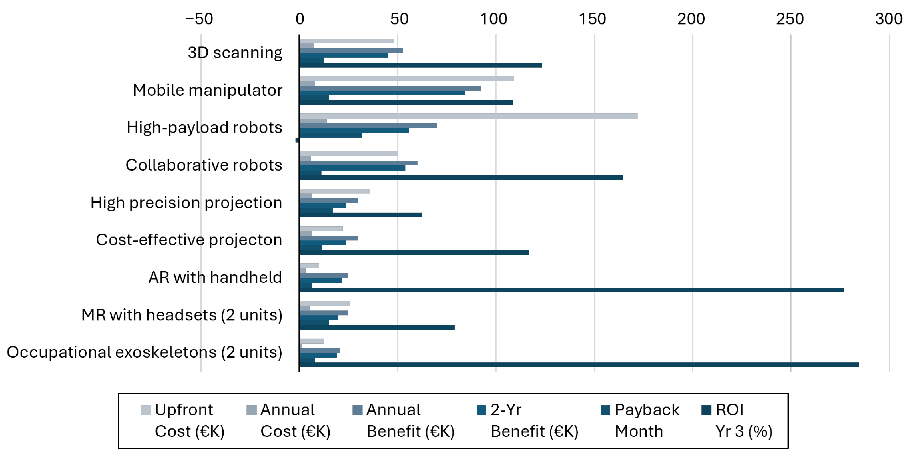
2.3.4. Cost and Benefit Analysis

In addition to the KPI evaluation, a comprehensive cost-benefit analysis was performed for each technology. Costs were assessed based on three main components: (1) purchase costs, encompassing the system’s hardware and software; (2) installation costs, including setup, calibration, and training of personnel; and (3) maintenance costs, covering routine maintenance, repairs, insurance, and software subscriptions. Benefits were determined using the criteria outlined in Table 1, with the highest-rated criteria selected to reflect user needs. As the technology remained at TRL 7, data on the full system deployment were derived from estimations rather than actual implementation benefits. Using the calculated costs and benefits, the estimated payback period, two-year net benefit, and return on investment (ROI) were computed for each technology, as shown in Figure 4.

3. Results

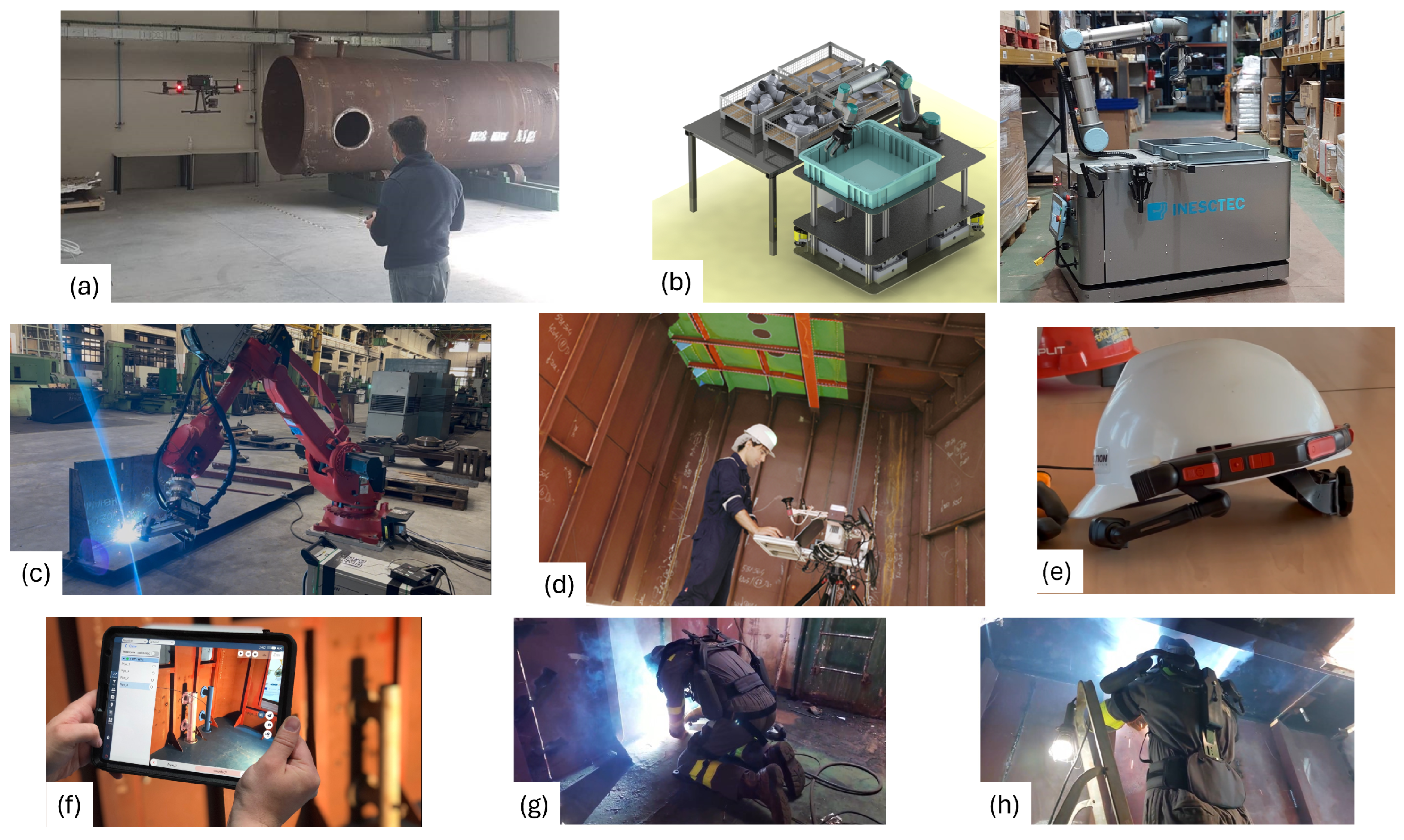
3.1. 3D Modeling and Digitalization
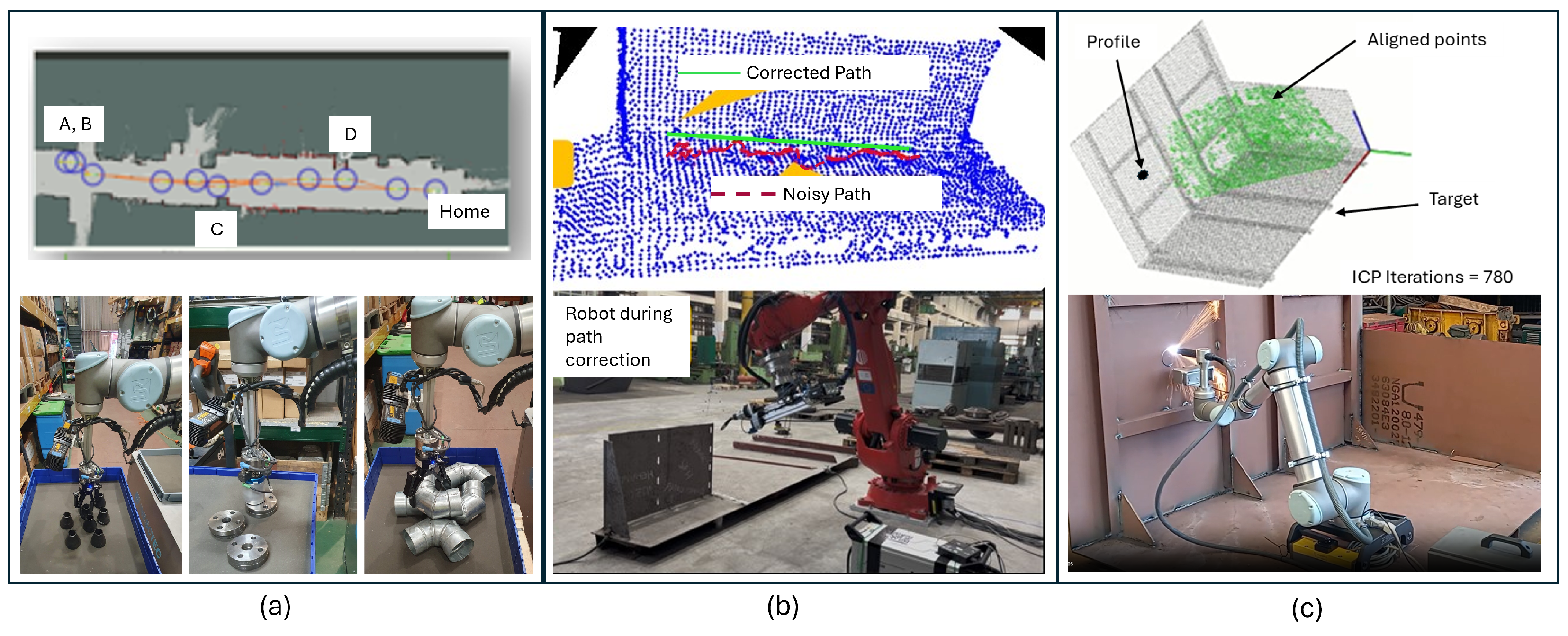
To demonstrate the capability of performing the 3D modeling of the shipyard, the facility was scanned through a drone mounting a LiDAR to obtain the point cloud representation of the shipyard facilities. This captured point cloud of the shipyard facilities was registered as the 3D base model, which could be navigated by operators through a dedicated application. The demonstration of the 3D scanning and digitalization focused on time saving, process control, and quality improvement. The use of 3D scanning tool combined with the 3D model was found to be a useful tool in areas with many installations, where a deviation in an element’s position can have a high impact on the installation of others. Figure 5a shows an example of the accuracy of the scanned information and its overlay on the actual design. The information is shown in terms of the model design and the actual design (as-designed vs as-built). Figure 5b shows the scanned area of the shipyard with the 3D point cloud and the simultaneous overlay on the RGB images, generating the digital twin with dimensions in horizontal and vertical directions. All time-related KPIs were achieved; in particular, the import and conversion of all elements were completed within the target time. Additionally, the percentage deviations in the measurements were 0.2% for the dock length and 0.5% for the storage area location, respectively.

3.2. Robotics

Autonomous Mobile Robots. The deployment of the autonomous mobile manipulator effectively demonstrated the capability to assist human operators in performing intra-logistics tasks, as illustrated in Figure 6a. They increased the ergonomics and attractiveness of these working positions. This allowed the human operator to spend more time on monitoring processes and other high-value tasks. A narrow corridor in the NODOSA warehouse (around 25 m long and 2.5–3 m wide), was selected as the testing environment; four different part-picking locations were defined. Moreover, five types with various geometries and sizes were selected from all the available parts in the warehouse to showcase the developed solution’s full capabilities. The robot was capable of navigating the warehouse autonomously and grasping a wide range of objects. Notably, the robotic solution was fully deployed in 1.5 days, demonstrating its usability and simplicity of operation. The solution achieved a 90% success rate across more than 20 tasks with varying picking requests and item types, using four different types of parts for the demonstration.
High-Payload Robots in Shared Spaces with Humans. The collaborative welding technologies utilizing high-payload robots at shipyard showed potential for improving ergonomics, reducing physical strain, and minimizing operator exposure to hazardous substances (Figure 6b). Furthermore, production efficiency could be enhanced, enabling operators to focus on tasks that require dexterity and contribute greater value. The demonstration involved the assembly of a real structure derived from an actual ship section. The assembly included several parts with varying shapes and sizes. To maintain easy replicability during the validation activities planned with multiple operators, we focused on the placements of two parts from the overall structure weighing 60 kg and 15 kg, respectively. Cycle time was reduced by 18%, exceeding the target of 5%, demonstrating improved productivity. Robot programming time for welding paths decreased by 90%, substantially higher than the 20% target, highlighting the system’s user-friendliness and efficiency. Low rapid upper limb assessment scores [51] demonstrated ergonomic enhancements. Additionally, non-ergonomic postures reduced compared to the original process, with a very positive average user satisfaction score, achieving the objectives for better working conditions. Lastly, the utilization of the hand-guiding system eliminated the need for external elevation system, reducing the cycle time by 2.4 min. These findings confirm that the system was capable of delivering enhanced operational efficiency alongside improved safety for human operators.
Collaborative Robots. The deployment of the collaborative robotic system demonstrated significant improvements in usability, process execution, and flexibility (Figure 6c). Notably, the deployment time of hardware and electrical component connections was reduced to 5 min (the target KPI was 10 min). This rapid deployment enabled faster setup and reduced downtime, allowing for increased productivity and efficiency. In addition, the time required for electrical component connections was also streamlined to 5 min. This efficient setup process set the stage for improved productivity, which was further enhanced by the system’s ability to perform cut openings 20% faster than manual tasks; however, it fell short of the 40% target. Finally, the accuracy in the cutting positioning of the robot was around 5–6 mm, where the maximum acceptable error was of 20 mm. Overall, the rapid deployment, efficient setup, and high accuracy boosted productivity, making this robotic system suitable for similar scenarios.

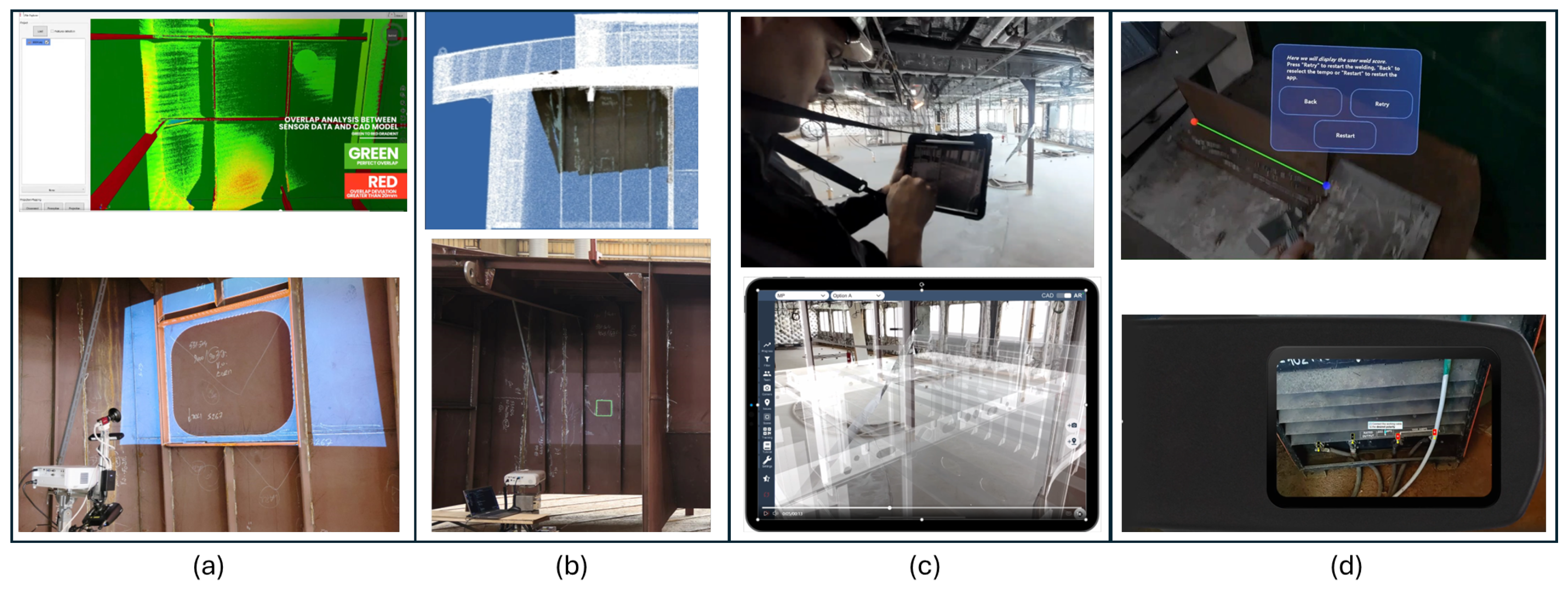
3.3. Augmented/Mixed Reality

High-Precision Projection Systems. High-precision projector-based technologies mainly improved productivity and efficiency by reducing reliance on printed documents, thus eliminating the need for manual measurement and marking tasks (Figure 7a). This led to a substantial reduction in human errors and rework, while also improving the precision and quality of finished products, such as cut openings. Furthermore, the technology supported the standardization of production information, ensuring higher consistency across processes. Specifically, tests demonstrated that the setup time was approximately 8 min, while the effective projection process required only around 97 s. In terms of time savings, a 73% reduction was achieved compared to traditional methods. Additionally, the system maintained a high level of precision, with projection errors consistently under 5 mm.
Cost-Effective Projection Systems. The deployment of the cost-effective projection system yielded improvements in usability, process execution, and flexibility (Figure 7b). The main task for the projection system was to demonstrate the procedure of making markings for cuttings in the hull construction within the allowed tolerance range for error. This was then compared to the standard procedure to obtain the final output data for the KPIs to verify whether this technology could outperform the one currently in use based on 2D paper drawings. Notably, the system eliminated the need for physical drawings, with almost no queries for physical paper. Furthermore, the system successfully demonstrated its versatility by being mounted on both the floor and the ceiling of ship structures, achieving the target of at least two distinct configurations. The system’s seamless integration with the existing environment was also achieved without requiring any additional site modifications. However, voltage fluctuations were observed, prompting the selection of a more suitable voltage regulator for future systems. The technology’s rapid deployment and removal, completed in less than 5 min, met initial expectations. While the system achieved the target KPIs, the projection system’s accuracy could still be improved.
Hand-Held and Head-Mounted AR/MR devices. Hand-held and head-mounted devices proved useful tools to improve training and process quality, increase operation completion, and reduce paper-based instructions and reporting (Figure 7c,d). In this work, they were used by workers as an additional tool while they performed their normal working tasks. It was estimated that through these systems, the time for checking the current status of a ship’s section reduced by about 30% with respect to the current practice. From the workers’ subjective perspective, there was an estimated increase in work satisfaction when using the digital assistant systems of about 30%. Overall, the workers who used these systems were very satisfied with them; they reported that it would help prevent rework and highlighted its ease of use, especially in localizing the necessary information for their daily work. Moreover, they reported having a 3D model with them to be highly beneficial, compared to carrying paper-based technical drawings, as well as benefits such as the possibility of reporting work progress and issues digitally and receiving prompt support from a remote supervisor.

3.4. Occupational Exoskeletons

The deployment of the OEs within the shipyard yielded positive results in terms of the KPIs identified, such as usability-related, health-related, and productivity-related indicators, after one month of use. This demonstrator was designed as a cross-over interventional investigation, consisting of a one-month baseline (BL) monitoring window and a one-month monitoring period (MP). The BL period served as a baseline condition to acquire data from a pool of workers in regular working conditions, allowing operators to access the technology during real working operations. Three workers participated in the OEs test campaign. The impact of the OEs was assessed by comparing the performance indicators measured in the one-month BL period, during which the operators performed their regular working activities without the OEs. Then, after training provided from the technology developers on the safe and effective use of the device, the three operators used the OEs during their regular work shift in the shipyard. The OEs were used in addition to the workers’ regular personal protective equipment, with compliance to all safety prescriptions. Figure 8 shows the main results achieved. During the one-month MP, the three workers used the OEs during work for a total of 96 h, corresponding to about 5 h/day (22% of the total work shift for each worker). Both OEs were positively evaluated in terms of usability. Workers were able to use the OEs regularly, except for tasks in confined spaces. Improvements were achieved in the reduction of pain occurrence with respect to the baseline period (−28% for the upper extremities with the shoulder support OE, −65% for the lower back with the lumbar support OE). Thanks to the use of the OEs, the physical effort perceived by the workers was reduced by 40%. Finally, both the number of breaks to rest and fatigue-induced errors were reduced by more than 50%. The results were positive. However, longer studies involving more workers are needed to confirm the device’s long-term usability in shipbuilding.

3.5. Training and Didactic Factories

The main implementation results include the 20 trainers who collaborated to design and deliver comprehensive training sessions. These sessions offered participants a well-rounded perspective on four main classes of technologies used by developers and end users. Tailored training materials were designed and developed for each of the nine training topics, helping over 170 participants from universities and the maritime industry. These training resources are accessible on the Mari4_YARD website. They can also be used in situ on the 10 pilot lines of the didactic factories, supporting continuous learning and practical experience.

4. Discussion

The successful implementation of the proposed portfolio of technologies developed within the Mari4_YARD project for the small to medium-sized shipyard industry hinges on overcoming several technical and operational challenges. Understanding these hurdles not only provides insights into potential risks but also lays the foundation for identifying best practices to guide future efforts. Hence, this section delves into the key challenges encountered during the development process, as well as the challenges faced to demonstrate these technologies in practice, and examines the strategies that proved most effective in addressing them. By doing so, it aims to offer actionable insights for stakeholders and researchers in the shipbuilding industry.
In the next sections, we first analyze the technical challenges, followed by operational issues. Finally, we highlight potential best practices and recommendations that emerged as critical to overcoming these barriers. It is worth noting that, given the multifaceted nature of the technologies developed, encompassing drones, heavy robotic platforms, collaborative robots, and wearable solutions, it was complex to generalize these challenges and thus draw common recommendations. Nevertheless, we endeavored to identify and highlight common themes across technologies (Table 3) or, when that was not possible, within each technological category.

4.1. Technical Challenges During Development

Technical challenges were the first main barrier encountered by technology developers. This barrier was mainly addressed due to the end users’ requirements related to the specific work tasks. Consequently, the technology was designed for the environmental constraints of the shipyard. These were typically associated with the expectations connected with the foreseen real-world application scenario.
  • Requirement to Specification Gap. A common issue was the prompt and clear identification of functional requirements from the end user’s perspective, which had to be translated into technical specifications by developers. This gap impacted the design and development phases of our solutions. Indeed, delays and uncertainties in identifying adequate requirements from the beginning of the design phase caused a cascade of additional delays, the development of initially sub-optimal solutions, and modifications to the requirements along the way.
  • Digital to Real Gap. Ensuring that physical environments match their digital counterparts, such as 3D CAD models, is key to effectively using projection systems and digital technologies [52]. The accuracy of these projection systems relied on how precise the digital models were. If the real world and its digital twin did not align, it could add inconsistencies during both the perception and projection stages, which could impair the system’s performance. One major issue was how ship structure deformation affected precision. Physical structures, especially in shipbuilding and industrial settings, can deform slightly due to material traits, temperature shifts, or mechanical stress. While 3D CAD models offer a theoretical design, they often ignore these real-world changes. The solution developed, based on a 3D point cloud registration algorithm used in the perception phase, was capable of handling outliers and proved to be resilient to these mismatches and deformations (in shipbuilding, most processes can handle deviations of up to ±5 cm).
  • TRL Gap. The technologies implemented did not all start from the same TRL. Indeed, within the various solutions implemented, some of them were already available on the market (e.g., high-payload robots, drones, head-mounted devices), whereas others were at a more prototypical stage (e.g., exoskeletons). Therefore, we observed technical challenges at different layers. On the one hand, in the case of projection systems or collaborative robots, the main technical challenges were not related to the platform itself, but rather to the specific applications they were used for. On the other hand, in the case of OEs, the maturity level of the technology was at a more prototypical stage (i.e., not commercially available), so technical challenges were encountered from the beginning of the design and development phase.
  • Environment Uncertainty Gap. Environment-related factors influenced the technical development, ranging from the presence of dusty, saline, and potentially explosive environments to the fact that these settings are heavily unstructured and inherently complex to target. In this context, for example, OEs were developed considering that the materials used needed to be resistant to flame, dust, and oxidation. Additionally, in the case of mobile robotic solutions, one of the main technical challenges was related to the fact that the shipyards were not yet ready for the deployment of such technologies, for example, due to component storage locations being organized to optimize space usage and human handling, which made the use of robotic devices challenging.

4.2. Operational Challenges During Demonstrations

The second main barrier encountered by technology providers was related to the operational challenges during the demonstrations at the end users’ facilities. These challenges represented the second layer to be overcome for technology demonstrations and future implementation. They were associated with the practical verification of the real conditions in which the developed technologies had to be implemented. Some cases required specific modifications and online adjustment to facilitate their correct integration and utilization within the shipyard’s environment and actual processes.
  • Environment Adaptation. In the context of autonomous mobile manipulators, their adaptation for specific applications required modifications tied to the warehouse’s item storage configuration. To validate this technology, adjustments were made to the storage layout, as illustrated in Figure 6a. Beyond these changes, no additional alterations to the warehouse environment were necessary. However, the adoption of mobile robots necessitated a careful evaluation of floor conditions. This assessment accounted for the type of wheels employed to ensure proper navigation and stability of the robot. For the use cases selected in this paper, and in typical warehouse settings, the floors were generally well-maintained, as they often accommodate pallet trucks for transporting parts. Consequently, no issues arose in this regard. Nevertheless, when deploying this solution to other locations, a thorough assessment of floor conditions remains essential to ensure operational success.
  • Software Integration. The integration of the provided solution into the already existing production systems—both hardware and software—was one of the main challenges that technology developers faced while implementing their solutions within the shipyards. In the case of the software, the concept of vertical integration was adopted. It focused on the static uploading of different data file formats collected from standard shipyard software tools. The verification of integration was performed by means of dedicated graphical user interfaces. However, there were still some challenges surrounding the day-to-day data updates. For example, it was verified that the existence of ERP systems, such as 3D models and resource planning, was not sufficient for many applications to effectively use the new technologies (e.g., digitalization through 3D scanning with drones). Indeed, if these systems are outdated, the physical environment may not correlate with the digitalized version (e.g., 3D models). This mismatch could result in manufacturing errors such as incorrect openings in hull structures. This was the case for the high-precision and cost-effective projection systems, where inadequate CAD model adaptability for in situ modifications hindered the ability to efficiently modify and update the developed models in real time.
  • Hardware Compatibility. The deployment of the pan-tilt unit projection system only required the presence of a horizontal ferromagnetic surface for attachment, whereas no additional modifications were necessary for on-site deployment. Additionally, ensuring compatibility between the new system’s hardware and the shipyard facility was a challenge. For example, power supply instability during one of the demonstrations at a shipyard risked damaging the projector system’s electrical components due to frequent voltage fluctuations. This was solved by implementing additional protective measures to ensure consistent power supply that were not foreseen in the design phase. The use of autonomous mobile robots in indoor environments suggested potential efficiency gains, but their application was constrained by factors such as floor conditions, robotic arm reachability, and payload limits. CAD models were necessary for part recognition, although ongoing research aims to eliminate this dependency. Challenges with reflective and transparent surfaces also highlighted the need for advancements in sensing and perception technologies [53]. Overall, these occurrences underscored the importance of developing robust and flexible solutions that can effectively address the complexity of real-world applications.
  • Operator Usability. A relevant challenge was providing solutions that could be easily operated by shipyards’ operators, without the need for dedicated specialized personnel, such as engineers from the developer’s side, during the daily work routine [54]. This issue arose when some parameters or device configurations needed real-time changes because the design did not match real conditions. This mismatch could be due to unforeseen changes in the working environment with respect to the design phase, such as in the case of collaborative robots. In this case, we faced localization problems, because the robot’s positioning was compromised due to the structure’s dimensions and limitations in the initial view selection. Also in this case, the problem was solved through manual intervention by the developers.
  • Productivity-Precision Balance. Maintaining a balance between cycle times and the precision of cutting and welding presented another challenge [55]. For example, with collaborative robots, we addressed this by splitting the process into two steps: robot teaching and automatic robotic operation. In the robot teaching step, the operator guides the robot to the correct position for the target ship structure, teaching it to reach the robotic working area for welding or cutting tasks. Then, in the second step, automatic robotic operation begins. From this point, the robot maintains a steady speed and accurately follows the planned paths. This method improved both precision and cycle time, particularly when welding similar profiles within the robot’s range of motion.
  • Environmental Operation. As far as the use of drones for 3D scanning of shipyards is concerned, it was faced the problem of obtaining proper flight permissions and managing the local fauna, namely the presence of birds in the aerial environment. Additionally, the shipyard workers in the scanning area posed a significant operational challenge. The presence of both humans and birds was a condition that needed to be avoided in order to properly perform acquisitions with drones.
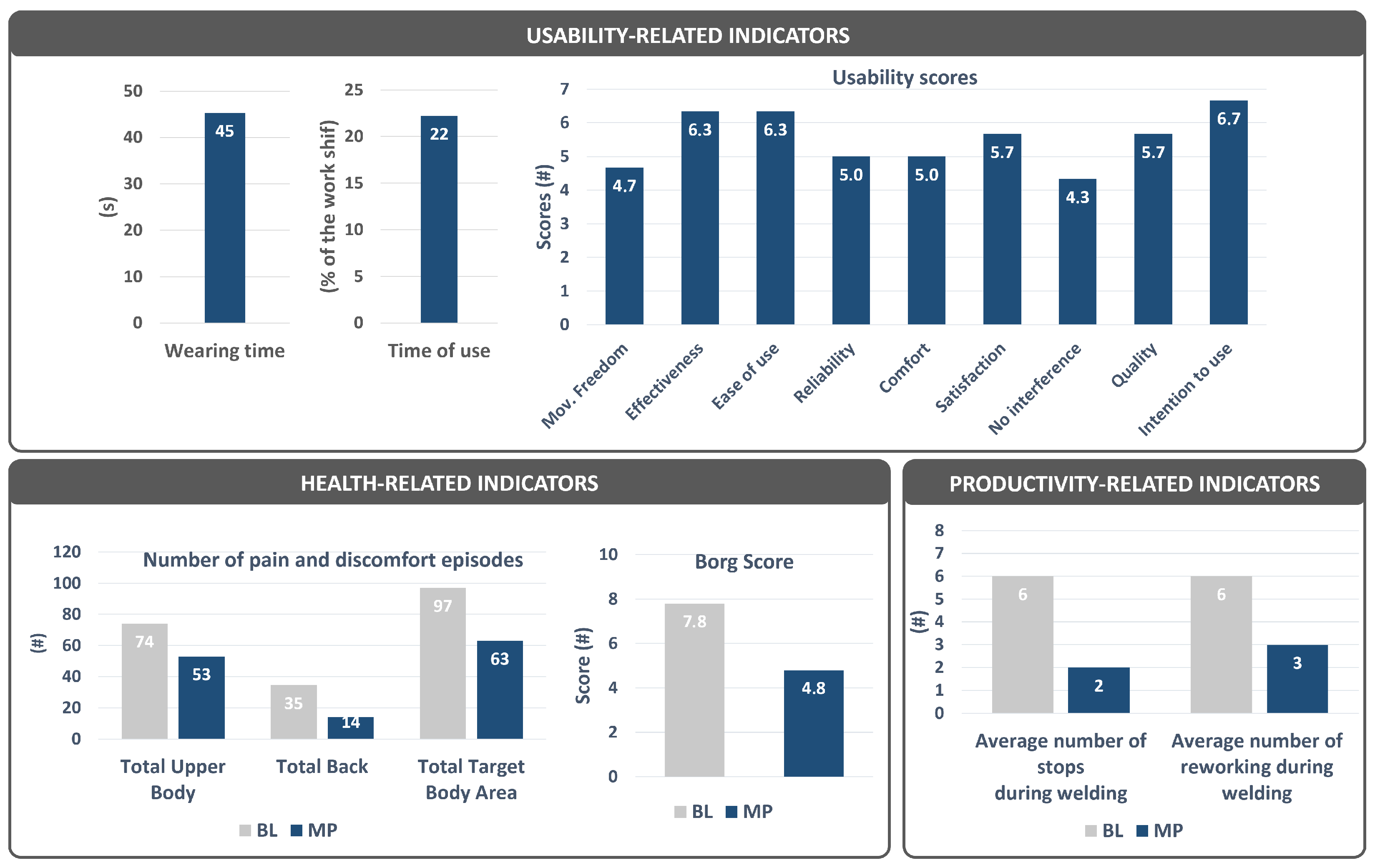
  • Long-Term Impact. In the case of the OEs, demonstration of their impact (or its estimation) in improving the quality of life of workers and enhancing productivity in the medium or long term is still lacking [56]. Hence, the primary challenge was to design an experimental procedure that could clearly highlight the medium- or long-term benefits of using exoskeletons compared to baseline working conditions. The procedural strategy implemented to demonstrate the benefit of the exoskeletons in the shipyards allowed us to effectively measure and demonstrate the medium-term impact of exoskeletons in reducing symptoms of musculoskeletal pain and discomfort and enhance productivity.
  • Economic Viability. The cost-benefit analysis emerged as a critical tool for evaluating the implementation potential of technologies at a higher TRL [57]. Our analysis revealed that most of the technology portfolio could achieve an ROI exceeding 100% by the end of three years. However, certain technologies, such as high-payload robots, high-precision systems, and mixed reality with headsets, would require a longer time frame to recover their initial investment costs. It is worth noting that the true benefits of these technologies could only be fully assessed post-implementation or through extended long-term deployment studies, which were outside the scope of this work. Moreover, the analysis was conducted based on the use cases under consideration. However, in practical scenarios, additional use cases within the industry could emerge as potential beneficiaries of the deployed technology, potentially leading to a higher return than what is estimated in this paper.

4.3. Best Practices and Recommendations

In this section, we attempt to summarize the main lessons learned in terms of best practices that could be derived from both the test sprint experiments and the on-site demonstrations carried out during the project. This section presents best practices from the Mari4_YARD experience as practical recommendations for implementing new technologies in shipbuilding.
  • Drone Application. While the use of drones for point cloud acquisition is highly promising, it will require careful planning and management. Regulatory requirements, local fauna interactions, and the presence of shipyard workers pose significant challenges. Mitigation strategies can be suggested, such as proper flight scheduling and the use of specialized devices to deter bird interference, to help overcoming these obstacles, although at an added cost.
  • Robotics Efficiency. The autonomous mobile manipulator brings both direct and indirect benefits to shipbuilding warehouses. It supports pre-planned logistics operations by using digitized warehouse data to receive tasks ahead of time, prepare them, and deliver parts to the requester. The robot also handles heavy and varied objects, managing items of different weights and sizes that are often too challenging for human workers to carry or move. When connected to the warehouse management system (WMS), it automatically records picking details, reducing errors in kit preparation and inventory registration for a more efficient and accurate process. Robotics also drives warehouse digitalization. This enables precise tracking of part locations and quantities, which human operators currently struggle to know exactly. This ensures complete registration and traceability of parts from arrival to departure, unlike the slow manual requesting and registering processes that lower productivity today. Overall, this highlights how robotics can boost efficiency, reduce human workload, and improve accuracy in shipyard warehouse operations.
  • Safety Compliance. Safety considerations are paramount in robotic systems, especially during deployment and task execution [58]. Proper training and the use of personal protective equipment are essential to mitigate risks [59]. The integration of collaborative robots also requires strict safety measures, especially for cutting or hazardous tasks and interaction with human operators on the shop floor.
  • AR/MR Implementation. The implementation of AR/MR systems relies on precise 3D models and controlled projection environments. Environmental factors, such as avoiding direct sunlight on projection surfaces, are critical for maintaining accuracy [60]. While wider projections are possible, they compromise precision and must be carefully considered in operational planning. Additionally, the use of head-mounted or hand-held devices as tools for digitalization highlighted the need for shipyards to embrace higher levels of technological maturity. Digital models and integration with existing ERP and PLM systems are prerequisites for their successful implementation and for successful future use. Effective knowledge organization, data security, and user training are also critical to maximize the benefits of these systems.
  • Training Simplicity. Since users have different levels of experience with AR/MR technologies, training sessions were included. Prototype training modules were integrated into both the web and mobile applications. During on-site trials, the workers using the tablet were given a short introduction, after which they were able to use the system without much difficulty. This, and the feedback we received, suggests that the application is easy to learn and user-friendly.
  • Exoskeleton Deployment. When considering the deployment of OEs, three main recommendations can be highlighted: First, providing structured training on how to use and operate exoskeletons can enhance user acceptance and usability. These sessions not only clarify technical aspects but also educate users on the benefits, ensuring smooth integration into daily routines. Second, establishing a dedicated area for exoskeleton storage, such as a locker room or a nearby corner, can make the devices accessible and facilitate easy donning and doffing. Third, gradually introducing workers to the technology helps them adapt to human–machine interaction at their own pace, ensuring comfort and respecting their physical conditions.
  • Training Consistency. Personnel training is a general aspect to be considered and homogeneously shared across almost all technologies. Indeed, through proper training activities shipyard’s operators can learn how to correctly use the new tools to enhance job efficiency, consequently reducing the barriers that could hinder their use in daily practice. This was particularly true for technologies that must be worn, such as head-mounted devices and exoskeletons. Moreover, the importance of this theme was recognized in the Mari4_YARD project, in which several training activities were conducted as previously reported.
  • Infrastructure Adaptation. Warehouses and shop floors would possibly need modifications to ensure proper integration of the new systems, in terms of, for example, spaces where components are stored that must be accessible to autonomous mobile robots. Additionally, the floor where robots will operate must be in a good state in order to enable the correct maneuverability of such systems. Ensuring the compliance of actual software infrastructures, such as ERP and PLC systems and CAD and 3D models, is necessary to ensure that new solutions can be effectively integrated and work synergistically with the existing system. This is a fundamental aspect that will be considered, especially in the case of projection systems and digitalization processes.
  • Sustainability. Finally, in the future, the long-term maintenance and support of these digital solutions could rely on licensing models with customer software support.

5. Conclusions

This paper presented the Mari4_YARD methodology and demonstration results of four human-centric technological blocks. The main demonstrations results can be summarized as follows: The use of drones can significantly enhance digital information collection for monitoring and production planning. High-payload robots can enhance ergonomics and reduce welding time, while advanced 3D scanning can improve monitoring accuracy. Collaborative robots can improve productivity and work quality by assisting in tasks that require high precision, such as metal cutting and welding, while allowing skilled workers to focus on more complex jobs. Cost-effective and high-precision projection systems can further streamline tasks and improve accuracy, particularly in outfitting and hull structure inspection. AR/MR technologies, including hand-held devices and headsets, can facilitate precise monitoring, commissioning, and training, enhancing communication and reducing paper usage. OEs can reduce operator fatigue, leading to higher productivity and reduced manufacturing errors. Didactic factories and cost-benefit analysis can serve as effective tools for implementation and deployment at small and medium-sized shipyards. However, these technologies faced both technical and operational challenges and will need further development to be effectively deployed and potentially included in everyday shipyard processes.

Author Contributions

Conceptualization, J.M., F.V. and L.G.; methodology, J.M., I.E. and S.V.F.; digitalization technologies, J.P.D.; robotics technologies, K.K.-S., S.G., S.M., N.D., A.K., A.M.P.L., L.F.R. and M.R.P.; AR/MR technologies, A.G. (Alejandro Grajeda), N.K., V.S., A.F.A., A.G. (Adam Gąsiorek) and M.N.; OE technologies, A.P., L.G. and S.C.; formal analysis, all authors; investigation, all authors; data curation, J.M. and L.G.; end user perspectives, J.P.M., L.N.R., R.M. and I.Z.; writing—original draft preparation, J.M. and L.G.; writing—review and editing, all authors; visualization, J.M. and L.G.; supervision, J.M.; project administration, A.R.V.; funding acquisition, F.V. All authors have read and agreed to the published version of the manuscript.

Funding

This work is part of the Mari4_YARD project, which has received funding from the European Union’s Horizon 2020 research and innovation programme under Grant Agreement n° 101006798.

Informed Consent Statement

Informed consent was obtained from all subjects involved.

Data Availability Statement

The dataset Mari4_YARD used in this study is available at https://zenodo.org/communities/mari4yard_2024/records?q=&l=list&p=1&s=10&sort=newest (accessed on 31 January 2025). These data are available in the public domain on the Zenodo platform.

Conflicts of Interest

Author Andrea Parri was employed by the company IUVO S.r.l. Authors Ivana Zeljkovic and Ratko Mimica were employed by the company Brodosplit. Authors Adam Gąsiorek and Michal Neufeld were employed by the company Transition Technologies PSC. Javier Pamies Durá was employed by the company GHENOVA Ingenieria. Javier Perez Mein and Lorena Núñez Rodriguez were employed by the company NODOSA SL. The remaining authors declare that the research was conducted in the absence of any commercial or financial relationships that could be construed as a potential conflict of interest.

Abbreviations

The following abbreviations are used in this manuscript:
AHPAnalytical hierachy process
AIArtificial intelligence
AR/MRAugmented/mixed reality
CADComputer-aided design
CobotCollaborative robot
DTDigital twin
KPIsKey performance indicators
ICPIterative closest point
LiDARLight detecting and ranging
OEsOccupational exoskeletons
PLMProduct lifecycle management
RGBRed green blue (color camera context)
RTOsResearch and technology organizations
SLAMSimultaneous localization and mapping
SMEsSmall to medium-sized enterprises
SMRCShip maintenance, repair, and conversion
TRLTechnology readiness level

References

  1. Atanasova, I.; Damyanliev, T.; Georgiev, P.; Garbatov, Y. Analysis of SME ship repair yard capacity in building new ships. In Progress in Maritime Technology and Engineering; CRC Press: Boca Raton, FL, USA, 2018; pp. 431–438. [Google Scholar]
  2. Munín-Doce, A.; Díaz-Casás, V.; Trueba, P.; Ferreno-González, S.; Vilar-Montesinos, M. Industrial Internet of Things in the production environment of a Shipyard 4.0. Int. J. Adv. Manuf. Technol. 2020, 108, 47–59. [Google Scholar] [CrossRef]
  3. Solesvik, M.Z. Interfirm collaboration in the shipbuilding industry: The shipbuilding cycle perspective. Int. J. Bus. Syst. Res. 2011, 5, 388–405. [Google Scholar] [CrossRef]
  4. Mickeviciene, R. Global Shipbuilding Competition: Trends and Challenges for Europe. In The Economic Geography of Globalization; Pachura, P., Ed.; IntechOpen: Rijeka, Croatia, 2011; Chapter 11. [Google Scholar] [CrossRef]
  5. Montwiłł, A.; Kasińska, J.; Pietrzak, K. Importance of key phases of the ship manufacturing system for efficient vessel life cycle management. Procedia Manuf. 2018, 19, 34–41. [Google Scholar] [CrossRef]
  6. Ebrahimi, A.; Brett, P.O.; Erikstad, S.O.; Asbjørnslett, B.E.; Agis, J.J.G. Ship design complexity, sources, drivers, and factors: A literature review. Int. Shipbuild. Prog. 2021, 67, 221–252. [Google Scholar] [CrossRef]
  7. Sánchez-Sotano, A.; Cerezo-Narváez, A.; Abad-Fraga, F.; Pastor-Fernández, A.; Salguero-Gómez, J. Trends of Digital Transformation in the Shipbuilding Sector. In New Trends in the Use of Artificial Intelligence for the Industry 4.0; Martínez, L.R., Rios, R.A.O., Prieto, M.D., Eds.; IntechOpen: Rijeka, Croatia, 2020; Chapter 1. [Google Scholar] [CrossRef]
  8. Hossain, K.A. Evaluation of Global and Local Shipbuilding Market. Sci. Technol. Public Policy 2023, 7, 52–68. [Google Scholar] [CrossRef]
  9. Arduino, G.; Aronietis, R.; Crozet, Y.; Frouws, K.; Ferrari, C.; Guihéry, L.; Kapros, S.; Kourounioti, I.; Laroche, F.; Lambrou, M.A.; et al. How to turn an innovative concept into a success? An application to seaport-related innovation. Res. Transp. Econ. 2013, 47, 1045–1063. [Google Scholar] [CrossRef]
  10. Luo, M.; Acciaro, M.; Verhetsel, A.; Sys, C. Innovation in the maritime sector: Aligning strategy with outcomes. Marit. Policy Manag. 2020, 47, 1045–1063. [Google Scholar] [CrossRef]
  11. Stanić, V.; Fafandjel, N.; Matulja, T. A Methodology for improving productivity of the existing shiipbuilding process using modern production concepts and the AHP method. Brodogradnja 2017, 68, 37–56. [Google Scholar] [CrossRef]
  12. Li, L.; Duan, L. Human centric innovation at the heart of industry 5.0–exploring research challenges and opportunities. Int. J. Prod. Res. 2025, 1–33. [Google Scholar] [CrossRef]
  13. Seppälä, L. Industry 5.0: Transforming ship design through human-centered approach. In Proceedings of the International Marine Design Conference, Delft, The Netherlands, 2–6 June 2024. [Google Scholar] [CrossRef]
  14. Ghobakhloo, M.; Mahdiraji, H.A.; Iranmanesh, M.; Jafari-Sadeghi, V. From Industry 4.0 digital manufacturing to Industry 5.0 digital society: A roadmap toward human-centric, sustainable, and resilient production. Inf. Syst. Front. 2024, 1–33. [Google Scholar] [CrossRef]
  15. Spoehr, J.; Jang, R.; Manning, K.; Rajagopalan, A.; Moretti, C.; Hordacre, A.L.; Howard, S.; Yaron, P.; Worrall, L. The Digital Shipyard: Opportunities and Challenges; Australian Industrial Transformation Institute, Flinders University of South Australia: Adelaide, Australia, 2020. [Google Scholar]
  16. Iwańkowicz, R.; Rutkowski, R. Digital Twin of Shipbuilding Process in Shipyard 4.0. Sustainability 2023, 15, 9733. [Google Scholar] [CrossRef]
  17. Herterich, M.M.; Uebernickel, F.; Brenner, W. The Impact of Cyber-physical Systems on Industrial Services in Manufacturing. Procedia CIRP 2015, 30, 323–328. [Google Scholar] [CrossRef]
  18. Kim, H.; Lee, S.S.; Park, J.H.; Lee, J.G. A model for a simulation-based shipbuilding system in a shipyard manufacturing process. Int. J. Comput. Integr. Manuf. 2005, 18, 427–441. [Google Scholar] [CrossRef]
  19. Fernandez-Andres, C.; Iborra, A.; Álvarez, B.; Pastor, J.; Pastor, J.A.; Sánchez, P.; Fernandez-Meroño, J.; Ortega, N.O. Ship shape in Europe: Cooperative robots in the ship repair industry. IEEE Robot. Autom. Mag. 2005, 12, 65–77. [Google Scholar] [CrossRef]
  20. Lee, J.; Kim, B.; Nam, M. Novel method for welding gantry robot scheduling at shipyards. Int. J. Prod. Res. 2022, 61, 5842–5859. [Google Scholar] [CrossRef]
  21. Galindo, P.L.; Morgado-Estévez, A.; Aparicio, J.L.; Bárcena, G.; Soto-Núñez, J.A.; Chavera, P.; Abad Fraga, F.J. Development of a customized interface for a robotic welding application at navantia shipbuilding company. In Proceedings of the ROBOT 2017: Third Iberian Robotics Conference, Sevilla, Spain, 22–24 November 2017; Springer: Cham, Switzerland, 2018; Volume 2, pp. 43–52. [Google Scholar] [CrossRef]
  22. Jones, J.E.; Rhoades, V.L.; Beard, J.; Arner, R.M.; Dydo, J.R.; Fast, K.; Bryant, A.; Gaffney, J.H. Development of a collaborative robot (COBOT) for increased welding productivity and quality in the shipyard. In Proceedings of the SNAME Maritime Convention, Providence, RI, USA, 4–6 November 2015; SNAME: Attica, Greece, 2015; p. D011S001R005. [Google Scholar] [CrossRef]
  23. Poggi, L.; Gaggero, T.; Gaiotti, M.; Ravina, E.; Rizzo, C.M. Robotic inspection of ships: Inherent challenges and assessment of their effectiveness. Ships Offshore Struct. 2022, 17, 742–756. [Google Scholar] [CrossRef]
  24. Molina Vargas, D.G.; Vijayan, K.K.; Mork, O.J. Augmented Reality for Future Research Opportunities and Challenges in the Shipbuilding Industry: A Literature Review. Procedia Manuf. 2020, 45, 497–503. [Google Scholar] [CrossRef]
  25. Fernández, R.P. How the industry 4.0 could affect the shipbuilding world. J. Marit. Res. 2020, 17, 18–27. [Google Scholar]
  26. Vidal-Balea, A.; Blanco-Novoa, O.; Fraga-Lamas, P.; Vilar-Montesinos, M.; Fernández-Caramés, T.M. A Collaborative Industrial Augmented Reality Digital Twin: Developing the Future of Shipyard 4.0. In Proceedings of the Science and Technologies for Smart Cities, Virtual Event, 2–4 December 2021; Paiva, S., Li, X., Lopes, S.I., Gupta, N., Rawat, D.B., Patel, A., Karimi, H.R., Eds.; Springer: Cham, Switzerland, 2022; pp. 104–120. [Google Scholar] [CrossRef]
  27. Toxiri, S.; Koopman, A.S.; Lazzaroni, M.; Ortiz, J.; Power, V.; de Looze, M.P.; O’Sullivan, L.; Caldwell, D.G. Rationale, Implementation and Evaluation of Assistive Strategies for an Active Back-Support Exoskeleton. Front. Robot. AI 2018, 5, 53. [Google Scholar] [CrossRef]
  28. Preethichandra, D.M.G.; Piyathilaka, L.; Sul, J.H.; Izhar, U.; Samarasinghe, R.; Arachchige, S.D.; de Silva, L.C. Passive and Active Exoskeleton Solutions: Sensors, Actuators, Applications, and Recent Trends. Sensors 2024, 24, 7095. [Google Scholar] [CrossRef]
  29. Schallock, B.; Rybski, C.; Jochem, R.; Kohl, H. Learning Factory for Industry 4.0 to provide future skills beyond technical training. Procedia Manuf. 2018, 23, 27–32. [Google Scholar] [CrossRef]
  30. Baena, F.; Guarin, A.; Mora, J.; Sauza, J.; Retat, S. Learning Factory: The Path to Industry 4.0. Procedia Manuf. 2017, 9, 73–80. [Google Scholar] [CrossRef]
  31. Vu, V.D.; Lützhöft, M.H. Improving human-centred design application in the maritime industry—Challenges and opportunities. Human Factors 2020, 19–20. [Google Scholar] [CrossRef]
  32. Santos, J.; Rebelo, P.M.; Rocha, L.F.; Costa, P.; Veiga, G. A* Based Routing and Scheduling Modules for Multiple AGVs in an Industrial Scenario. Robotics 2021, 10, 72. [Google Scholar] [CrossRef]
  33. Cordeiro, A.; Rocha, L.F.; Costa, C.; Silva, M.F. Object Segmentation for Bin Picking Using Deep Learning. In Proceedings of the ROBOT2022: Fifth Iberian Robotics Conference, Zaragoza, Spain, 23–25 November 2022; Tardioli, D., Matellán, V., Heredia, G., Silva, M.F., Marques, L., Eds.; Springer: Cham, Switzerland, 2023; pp. 53–66. [Google Scholar]
  34. Cordeiro, A.; Souza, J.P.; Costa, C.M.; Filipe, V.; Rocha, L.F.; Silva, M.F. Bin Picking for Ship-Building Logistics Using Perception and Grasping Systems. Robotics 2023, 12, 15. [Google Scholar] [CrossRef]
  35. Katsampiris-Salgado, K.; Dimitropoulos, N.; Michalos, G.; Makris, S. Suitability assessment method for safe robot tooling design in Human-Robot Collaborative applications. Procedia CIRP 2024, 128, 770–775. [Google Scholar] [CrossRef]
  36. Masood, J.; Vidal, F.; Castro, D.; Pertusa, A.M.; Feijoo, A. Robotized technologies for enhanced shipyard operations: Challenges and solutions. Green Manuf. Open 2024, 2, 6. [Google Scholar] [CrossRef]
  37. Afzal Maken, F.; Muthu, S.; Nguyen, C.; Sun, C.; Tong, J.; Wang, S.; Tsuchida, R.; Howard, D.; Dunstall, S.; Petersson, L. Improving 3D Reconstruction Through RGB-D Sensor Noise Modeling. Sensors 2025, 25, 950. [Google Scholar] [CrossRef]
  38. Mimica, R.; Željković, I.; Settler, V.; Köster, N.; Gąsiorek, A.; Neufeld, M. Technology Evaluation of Augmented and Mixed Reality Systems in Shipbuilding Processes: Preliminary Report. In Theory and Practice of Shipbuilding; IOS Press: Amsterdam, The Netherlands, 2024; pp. 298–313. [Google Scholar] [CrossRef]
  39. Theurel, J.; Desbrosses, K. Occupational exoskeletons: Overview of their benefits and limitations in preventing work-related musculoskeletal disorders. IISE Trans. Occup. Ergon. Hum. Factors 2019, 7, 264–280. [Google Scholar] [CrossRef]
  40. de Looze, M.P.; Bosch, T.; Krause, F.; Stadler, K.S.; O’Sullivan, L.W. Exoskeletons for industrial application and their potential effects on physical work load. Ergonomics 2016, 59, 671–681. [Google Scholar] [CrossRef]
  41. Rashedi, E.; Kim, S.; Nussbaum, M.A.; Agnew, M.J. Ergonomic evaluation of a wearable assistive device for overhead work. Ergonomics 2014, 57, 1864–1874. [Google Scholar] [CrossRef] [PubMed]
  42. Theurel, J.; Desbrosses, K.; Roux, T.; Savescu, A. Physiological consequences of using an upper limb exoskeleton during manual handling tasks. Appl. Ergon. 2018, 67, 211–217. [Google Scholar] [CrossRef] [PubMed]
  43. Kim, S.; Nussbaum, M.A.; Mokhlespour Esfahani, M.I.; Alemi, M.M.; Alabdulkarim, S.; Rashedi, E. Assessing the influence of a passive, upper extremity exoskeletal vest for tasks requiring arm elevation: Part I—“Expected” effects on discomfort, shoulder muscle activity, and work task performance. Appl. Ergon. 2018, 70, 315–322. [Google Scholar] [CrossRef] [PubMed]
  44. Bosch, T.; van Eck, J.; Knitel, K.; de Looze, M. The effects of a passive exoskeleton on muscle activity, discomfort and endurance time in forward bending work. Appl. Ergon. 2016, 54, 212–217. [Google Scholar] [CrossRef]
  45. Huysamen, K.; de Looze, M.; Bosch, T.; Ortiz, J.; Toxiri, S.; O’Sullivan, L.W. Assessment of an active industrial exoskeleton to aid dynamic lifting and lowering manual handling tasks. Appl. Ergon. 2018, 68, 125–131. [Google Scholar] [CrossRef]
  46. Grazi, L.; Trigili, E.; Proface, G.; Giovacchini, F.; Crea, S.; Vitiello, N. Design and Experimental Evaluation of a Semi-Passive Upper-Limb Exoskeleton for Workers with Motorized Tuning of Assistance. IEEE Trans. Neural Syst. Rehabil. Eng. 2020, 28, 2276–2285. [Google Scholar] [CrossRef]
  47. Ramella, G.; Grazi, L.; Giovacchini, F.; Trigili, E.; Vitiello, N.; Crea, S. Evaluation of antigravitational support levels provided by a passive upper-limb occupational exoskeleton in repetitive arm movements. Appl. Ergon. 2024, 117, 104226. [Google Scholar] [CrossRef]
  48. Grazi, L.; Trigili, E.; Caloi, N.; Ramella, G.; Giovacchini, F.; Vitiello, N.; Crea, S. Kinematics-Based Adaptive Assistance of a Semi-Passive Upper-Limb Exoskeleton for Workers in Static and Dynamic Tasks. IEEE Robot. Autom. Lett. 2022, 7, 8675–8682. [Google Scholar] [CrossRef]
  49. Kanakis, A.; Katsampiris-Salgado, K.; Zacharaki, N.; Dimitropoulos, N.; Makris, S. Cognitive Exoskeletons: Harnessing AI for Enhanced Wearable Robotics in Shipbuilding. In Advances in Artificial Intelligence in Manufacturing; Wagner, A., Alexopoulos, K., Makris, S., Eds.; Springer Nature: Cham, Switzerland, 2024; pp. 126–135. [Google Scholar]
  50. Lanotte, F.; Baldoni, A.; Dell’ Agnello, F.; Scalamogna, A.; Mansi, N.; Grazi, L.; Chen, B.; Crea, S.; Vitiello, N. Design and characterization of a multi-joint underactuated low-back exoskeleton for lifting tasks. In Proceedings of the 2020 8th IEEE RAS/EMBS International Conference for Biomedical Robotics and Biomechatronics (BioRob), New York, NY, USA, 29 November 2020–1 December 2020; IEEE: Piscataway, NJ, USA, 2020; pp. 1146–1151. [Google Scholar] [CrossRef]
  51. McAtamney, L.; Nigel Corlett, E. RULA: A survey method for the investigation of work-related upper limb disorders. Appl. Ergon. 1993, 24, 91–99. [Google Scholar] [CrossRef]
  52. Blanco-Novoa, O.; Fernández-Caramés, T.M.; Fraga-Lamas, P.; Vilar-Montesinos, M.A. A Practical Evaluation of Commercial Industrial Augmented Reality Systems in an Industry 4.0 Shipyard. IEEE Access 2018, 6, 8201–8218. [Google Scholar] [CrossRef]
  53. Jiang, J.; Cao, G.; Deng, J.; Do, T.T.; Luo, S. Robotic Perception of Transparent Objects: A Review. IEEE Trans. Artif. Intell. 2024, 5, 2547–2567. [Google Scholar] [CrossRef]
  54. Hsieh, M.H.; Xia, Z.; Chen, C.H. Human-centred design and evaluation to enhance safety of maritime systems: A systematic review. Ocean Eng. 2024, 307, 118200. [Google Scholar] [CrossRef]
  55. Brogårdh, T. Present and future robot control development—An industrial perspective. Annu. Rev. Control 2007, 31, 69–79. [Google Scholar] [CrossRef]
  56. Botti, L.; Melloni, R. Occupational Exoskeletons: Understanding the Impact on Workers and Suggesting Guidelines for Practitioners and Future Research Needs. Appl. Sci. 2024, 14, 84. [Google Scholar] [CrossRef]
  57. Jha, S. Emerging technologies: Impact on shipbuilding. Marit. Aff. J. Natl. Marit. Found. India 2016, 12, 78–88. [Google Scholar] [CrossRef]
  58. Eder, K.; Harper, C.; Leonards, U. Towards the safety of human-in-the-loop robotics: Challenges and opportunities for safety assurance of robotic co-workers’. In Proceedings of the 23rd IEEE International Symposium on Robot and Human Interactive Communication, Edinburgh, UK, 25–29 August 2014; pp. 660–665. [Google Scholar] [CrossRef]
  59. Fraguela Formoso, J.A.; López-Arranz, A.; Guerreiro, M.J.R.; Lamas-Galdo, I. Management of the Prevention of Labor Risks in Construction and Repair Shipyards. In Proceedings of the 25th Pan-American Conference of Naval Engineering—COPINAVAL, Panama City, Panama, 16–19 October 2017; Vega Sáenz, A., Pereira, N.N., Carral Couce, L.M., Fraguela Formoso, J.A., Eds.; Springer: Cham, Switzerland, 2019; pp. 461–472. [Google Scholar] [CrossRef]
  60. Zhan, T.; Yin, K.; Xiong, J.; He, Z.; Wu, S.T. Augmented Reality and Virtual Reality Displays: Perspectives and Challenges. iScience 2020, 23, 101397. [Google Scholar] [CrossRef]
Figure 1. The Mari4_YARD methodology: (0) requirements of end users; (1) preparation; (2) setup; (3) test; (4) evaluation; and (5) transfer knowledge.
Electronics 14 01597 g001
Figure 2. Portfolio of the technological solutions developed for the shipbuilding industry scenario.
Electronics 14 01597 g002
Figure 3. Portfolio of technological solutions: (a) drone for the digitalization and 3D scanning; (b) autonomous mobile robot; (c) high-payload robot; (d) high-precision projection; (e) AR/MR headsets; (f) AR/MR hand-held tablet; (g) lumbar support occupational exoskeleton; (h) shoulder support occupational exoskeleton.
Electronics 14 01597 g003
Figure 4. Technology cost-benefit analysis and return on investment (ROI) estimates.
Electronics 14 01597 g004
Figure 5. Results of the digitalization and 3D modeling: (a) digital verification and comparison of digital models with fixed scanner; (b) 3D scanned production facilities interface with drone.
Electronics 14 01597 g005
Figure 6. Results of robotics at SMEs shipyards: (a) autonomous mobile robots localization and bin picking at the warehouse. A–D are the different objects picking points; (b) high-payload localization of the welding path on the ship structure; and (c) collaborative robot performing localization and plasma cutting.
Electronics 14 01597 g006
Figure 7. Results of AR/MR system at SMEs shipyards: (a) high-precision projection localization w.r.t. the CAD model; (b) cost-effective projection high-payload localization w.r.t. the CAD model; (c) localized information overlay on the tablet; and (d) localized instruction and information on the headset.
Electronics 14 01597 g007
Figure 8. Results of the occupational exoskeletons demonstrator, showing the impact on usability-related, health-related, and productivity-related indicators.
Electronics 14 01597 g008
Table 1. End users’ needs heatmap. The main criteria for the selection of the KPIs. Technologies and their impact across different criteria.
TechnologyTime SavingProcess ControlQualityCostSafetyErgonomics
ImprovementImprovementReductionImprovementImprovements
3D scanning0.80.70.60.40.20.1
Mobile manipulator0.70.60.80.50.40.3
High-payload robots0.60.50.40.20.40.3
Collaborative robots0.80.70.90.60.50.4
High-precision projection0.40.30.60.20.10.0
Cost-effective projection0.30.20.50.10.00.0
AR with handheld0.50.40.70.30.20.1
MR with headsets0.60.50.80.40.30.2
Occupational exoskeletons0.20.10.40.10.90.8
Table 2. Summary of the key performance indicators. KPIs for each technology are reported, grouped by the main four identified categories, along with target values as well as achieved results.
TechnologyKPITargetResult
3D modeling and digitalization
Time to import point clouds/3D CAD elements (with format conversion)<10 min (<15 min)Achieved
Time to import a ship block and locate it in open storage area/slipway<15 min (<30 min)Achieved
Deviation in length measurement≤0.5%0.2%
Deviation in area measurement≤1%0.5%
Robotics
Autonomous mobile manipulator
Time to setup the full system in place1.5 daysAchieved
System reliability≥95%90%
Operators freed for other operations≥1 operatorAchieved
High-payload robots
Cycle time reduction>5%18%
Reduction of robot programming time>20%90%
Improved ergonomics scores1 < score < 4Achieved
Time diff. with/without hand-guiding assistance≤2 min2.4 min
Use of external assistance to handle loads0Achieved
Collaborative robots
Hardware component deployment time<10 min5 min
Time for electrical component connection<5 min5 min
Time for cut opening vs manual≤40%20%
Robot position and cut accuracy error≤20 mm5–6 mm
Augmented/Mixed Reality
High-precision projection
Time to setup system10 min8 min
Precision error of projection<5 mmAchieved
Time saved vs traditional approach≥70%73%
Rework reduction80%Achieved
Cost-effective projection
Reduce paper drawing usage<1 queryAchieved
Mounting configurations≥22
Onsite rework reduction≤60%Achieved
Install/remove projector time<5 minAchieved
AR with hand-held devices
Perform working task time<5 min2 min
Report/review issues time<60 min20 min
Document machine state time<30 min3 min
MR with headsets
Training time reduction≥25%Achieved
Reduction in training material writing≥80%Achieved
Occupational exoskeletons
Weekly utilization>20%22%
Usability≥55.5
Wearing/unwearing time<60 s45 s
Pain events reduction>50%28% (shoulder),
65% (lumbar)
Fatigue reduction vs baseline>25%40%
Assembly error reduction>30%50%
Breaks reduction due to pain>30%66%
Table 3. Summary overview of technical and operational challenges encountered. For each challenge, the involved technologies are shown.
Technical Challenges
ChallengesTechnologies
Prompt and clear identification of functional requirementsElectronics 14 01597 i001Electronics 14 01597 i002Electronics 14 01597 i003Electronics 14 01597 i004
Match between physical environment and its digital versionElectronics 14 01597 i001Electronics 14 01597 i002Electronics 14 01597 i003
Initial technologies’ TRLElectronics 14 01597 i001Electronics 14 01597 i002Electronics 14 01597 i003Electronics 14 01597 i004
Environment-related factorsElectronics 14 01597 i001Electronics 14 01597 i002Electronics 14 01597 i003Electronics 14 01597 i004
Operational Challenges
ChallengesTechnologies
Modification of the shipyardElectronics 14 01597 i001
Integration of developed solutions into existing systemsElectronics 14 01597 i001Electronics 14 01597 i002Electronics 14 01597 i003
Compliance of developed solutions with actual shipyard’s systemsElectronics 14 01597 i001Electronics 14 01597 i002Electronics 14 01597 i003
Easy-to-operate solutionsElectronics 14 01597 i001Electronics 14 01597 i002Electronics 14 01597 i003Electronics 14 01597 i004
Ensuring adequate work operations performance and quality compared to current practiceElectronics 14 01597 i001Electronics 14 01597 i002Electronics 14 01597 i003Electronics 14 01597 i004
Obtaining flight permissionsElectronics 14 01597 i001
Planning prolonged time use of the developed solutions to improve workers well-being over time Electronics 14 01597 i004
Electronics 14 01597 i001 3D modeling and digitalization; Electronics 14 01597 i002 Robotics; Electronics 14 01597 i003 Augmented/Mixed Reality; Electronics 14 01597 i004 Occupational exoskeletons.
Disclaimer/Publisher’s Note: The statements, opinions and data contained in all publications are solely those of the individual author(s) and contributor(s) and not of MDPI and/or the editor(s). MDPI and/or the editor(s) disclaim responsibility for any injury to people or property resulting from any ideas, methods, instructions or products referred to in the content.

