Abstract
To address the high-frequency resonance issues in renewable energy systems integrated via MMC-HVDC transmission under weak grid conditions, this paper establishes a wide-frequency sequence impedance model for renewable energy grid-side converters and MMC-HVDC sending-end converters. The impedance characteristics of the MMC-HVDC transmission system under two distinct control modes are compared, and the constant power control mode is selected for detailed analysis to better evaluate the effectiveness of suppression strategies. Based on this framework, the superposition theorem is employed to analyze the interaction mechanism between the impedance characteristics of the MMC-HVDC sending-end converter and the renewable energy grid-connected system. Since the aim of this study is to propose suppression strategies for the MMC-HVDC transmission system, a sensitivity analysis of its control parameters is conducted. The results identify the current loop and voltage feedforward control as the dominant factors influencing high-frequency oscillations. Accordingly, a coordinated control strategy combining current loop regulation and voltage feedforward compensation is proposed. An electromagnetic transient simulation model is developed in MATLAB/Simulink. The simulations demonstrate that the proposed strategy effectively suppresses oscillations in the MMC-HVDC system across high-frequency ranges. Furthermore, it avoids negative damping characteristics within a broad frequency band, significantly enhancing the steady-state performance of renewable energy systems integrated via MMC-HVDC transmission.
1. Introduction
The modular multilevel converter (MMC) is widely recognized for its superior performance characteristics, suitability for renewable energy integration, and enhanced grid support capabilities. These features make it widely applicable in isolated island power transmission, offshore wind power DC transmission, and other related fields [1,2,3,4].
Resonance issues have been observed in multiple MMC-HVDC transmission system globally, compromising power system safety. Notable incidents include a 450 Hz medium–high-frequency oscillation in the German North Sea MMC-HVDC transmission system and 1000 Hz oscillations in the Zhoushan High-Voltage Direct Current project in Zhejiang Province, China [5]. To prevent such oscillations in future projects, it is critical to investigate the oscillation mechanisms of new energy systems integrated via a modular multilevel converter—high-voltage direct current.
Impedance analysis and eigenvalue analysis are two dominant techniques for power system stability assessment. The former demonstrates superior intuitiveness and practical applicability compared to eigenvalue-based approaches. It enables rapid stability analysis in multi-machine systems and in scenarios where parameter variations alter the network structure. Accurate and comprehensive modeling is a prerequisite for system stability analysis [6]. Existing and well-established impedance modeling methods include the multi-harmonic linearization method [7,8,9] and the harmonic state-space (HSS) method [10,11,12].
For instance, studies [13,14] modularly modeled the MMC control link using the HSS method to investigate the impact of parameter variations on system stability, but a complete control system model was not established. Study [15] proposed an impedance sensitivity assessment method to identify the dominant factors affecting system stability but did not provide a targeted resonance suppression strategy. Study [16] adopted the HSS modeling method to establish a small-signal model of the system. The analysis revealed that the phase-locked loop, outer control loops, and circulating current suppression loops exhibited a negligible influence on high-frequency oscillations. Study [17] conducted a comparative analysis between the harmonic linearization and HSS methods, deriving impedance models for both approaches. However, these models did not comprehensively cover all control links, necessitating the development of a complete impedance model incorporating all control loops.
An oscillation suppression method incorporating a low-pass filter within the feedforward architecture was presented in study [18]. However, this strategy not only failed to fully elevate the damping properties of the modular multilevel converter—high-voltage direct current at specific frequencies, but also could not entirely eliminate the risk of medium–high-frequency oscillations. An innovative solution to control delay-induced instability was proposed in paper [19], featuring an adaptive band-stop filter integrated into the current inner loop. Study [20] presented a dual-path inhibition method by embedding low-pass filters in both the voltage feedforward and current proportional–integral control paths. Study [21] designed an auxiliary controller based on passive control theory. Nevertheless, these approaches did not comprehensively evaluate their impact across the entire high-frequency range. While the aforementioned methods have effectively suppressed the harmonic phenomenon in MMC-HVDC systems, they may fail to fully eliminate the exposures of the medium–high-frequency-band harmonic phenomenon.
To address the aforementioned issues, this study first builds up a sequence impedance model for renewable energy integration through MMC-HVDC systems across wide frequency bands. Building upon this theoretical foundation, a sensitivity analysis of different control parameters in the MMC-HVDC transmission system reveals that the current inner-loop control and voltage feedforward mechanism constitute the dominant factors influencing system resonance. Considering the large-scale deployment of renewable energy stations, resonance suppression strategies are proposed for the sending-end system. Through comparative analysis of impedance characteristics under two control modes in MMC-HVDC transmission systems, the constant power control mode is selected for a detailed investigation. A coordinated control methodology integrating voltage feedforward compensation and current loop optimization is developed using dominant factor analysis to mitigate oscillation phenomena. Electromagnetic transient simulation results ultimately validate the effectiveness of the proposed control strategy.
2. Renewable Energy Integration via Modular Multilevel Converter—High-Voltage Direct Current Transmission System
2.1. System Architecture
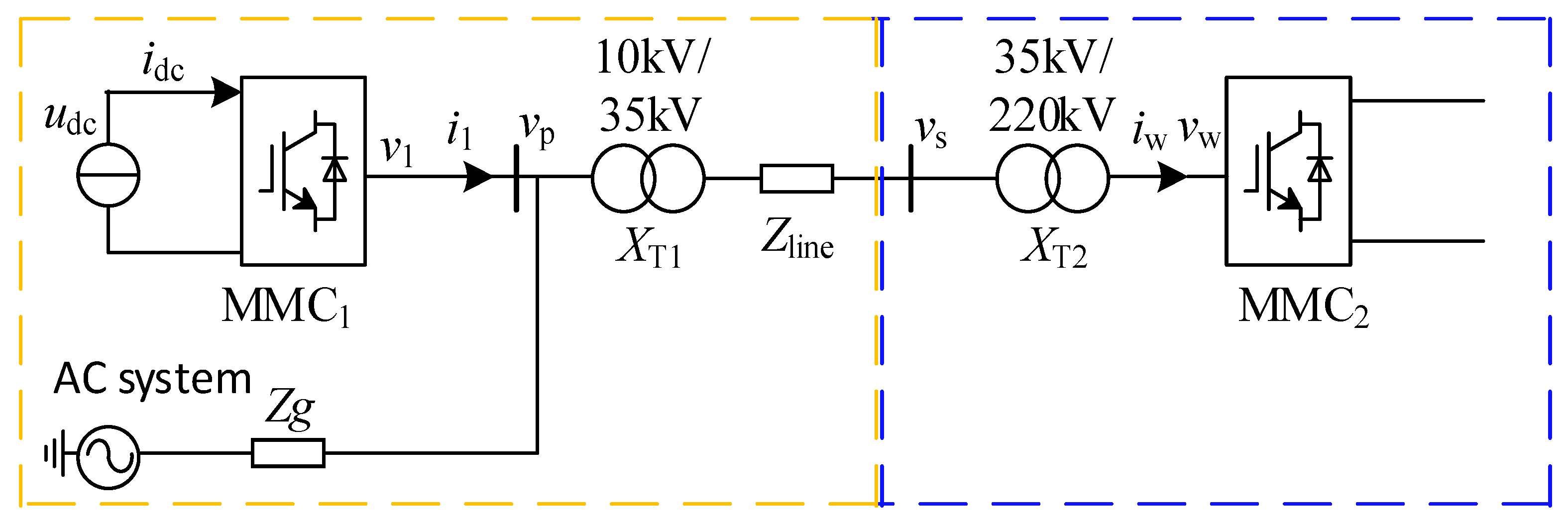
Figure 1 illustrates the architecture of the Renewable Energy Integration System using MMC-HVDC Transmission under weak grid conditions. Both the renewable energy grid-side converter and the MMC-HVDC sending-end converter use grid-following MMC, hereinafter referred to as MMC1 and MMC2, respectively, with fixed DC potential and Q-power adjustment for MMC1 and constant power control for MMC2. The renewable energy station interfaces with the PCC via a step-up conversion unit and AC transmission line, extending the conventional single-inverter grid connection topology to link with the converter station. Each variable is defined as follows: udc is the DC bus voltage of the MMC1; vp is the common coupling point potential of the MMC1; v1 and i1 are the output electrical parameters of the MMC1 converter; vs is the voltage of the PCC point; XT1 and XT2 are the leakage impedance of the two-stage step-up transformer; and vw and iw are the output electrical parameters of the MMC2, respectively.
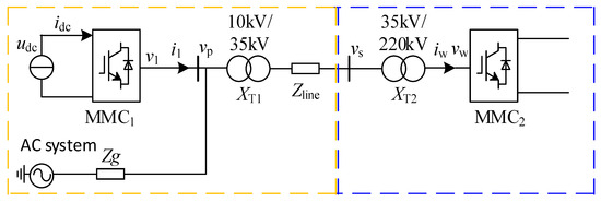
Figure 1.
System architecture of renewable energy integration via MMC-HVDC transmission system under weak grid conditions.
2.2. System Impedance Modeling and Characterization
Figure 2 details the coupled power circuit topology and closed-loop control logic for MMC1/MMC2, where L is the inductance of the bridge arm; C is the submodule capacitance, Ceq is the equivalent capacitance, and Ceq = C/N, Hp(s) is the active power outer-loop PI control; HQ(s) is the reactive power outer-loop PI control; HV(s) is the dc voltage outer-loop PI control; Hi(s) and Ki are the current-loop PI control and decoupling terms, respectively; Hc(s) and Kc are defined as the circulating current PI transfer function and decoupling terms, respectively; and kf is the voltage feedforward coefficient.
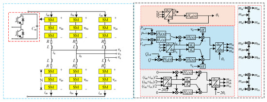
Figure 2.
Power topology and control block diagram for MMC1 and MMC2.
According to the MMC single bridge arm operating principle and KCL equation, the frequency domain steady state model of the MMC main circuit is
The modulation factor represents the connection between each control loop. The coupling dynamics of the modulation factor and control loops are mathematically formulated as
where , , , , , and denote the connection between each control loop and the modulation factor.
The current inner-loop dynamics are governed by
Gi is represented as by the auxiliary functions and :
where is the transfer function of the current control inner-loop PI controller, and is the decoupling coefficient in the current inner loop.
The auxiliary function in Equation is used to characterize the phase sequence of the physical quantities of the three-phase bridge arm.
is used to characterize the phase sequence
The loop control can be expressed as
where Gc represents the effect of current loop suppression on the modulation factor, and is expressed as
The effect of the phase-locked loop on the modulation factor can be expressed as
The elements in the matrix are as follows:
where Tpll is the closed-loop transfer function of the phase-locked loop.
The effect of power control on the modulation factor can be expressed as
Gp and Gq can be expressed as
The elements in the matrices VP, VQ and IP, IQ of Equation are distributed in the following form:
where Uv is the Ac voltage, and Iu,k represents the Fourier complex factor of the k-th steady state harmonic.
The DC voltage control can be expressed as
The control matrices GV and Gir are expressed as follows:
The voltage feedforward link can be expressed as
The bridge arm impedance YL and the capacitive impedance ZC are expressed as
2.3. AC Side Impedance Modeling of MMC1 and MMC2
After modeling each control link individually, all the control links are combined to obtain the effect of the modulation factors on the whole control system.
can be expressed as
where denotes the control link delay, and and are the effect of the upper bridge arm current and AC voltage on the modulation factor , respectively.
where U is the unit matrix, and the matrices Ai and Av in Equation represent the effect of and on the AC-side conductance Yac.
The expression for MMC1 is shown below:
The expression for MMC2 is shown below:
3. Analysis of High-Frequency Oscillation Mechanism of Renewable Energy Integration via Modular Multilevel Converter—High-Voltage Direct Current Transmission System Under Weak Grid Conditions
3.1. Impedance Characterization of Modular Multilevel Converter—High-Voltage Direct Current Systems Under Different Control Methods
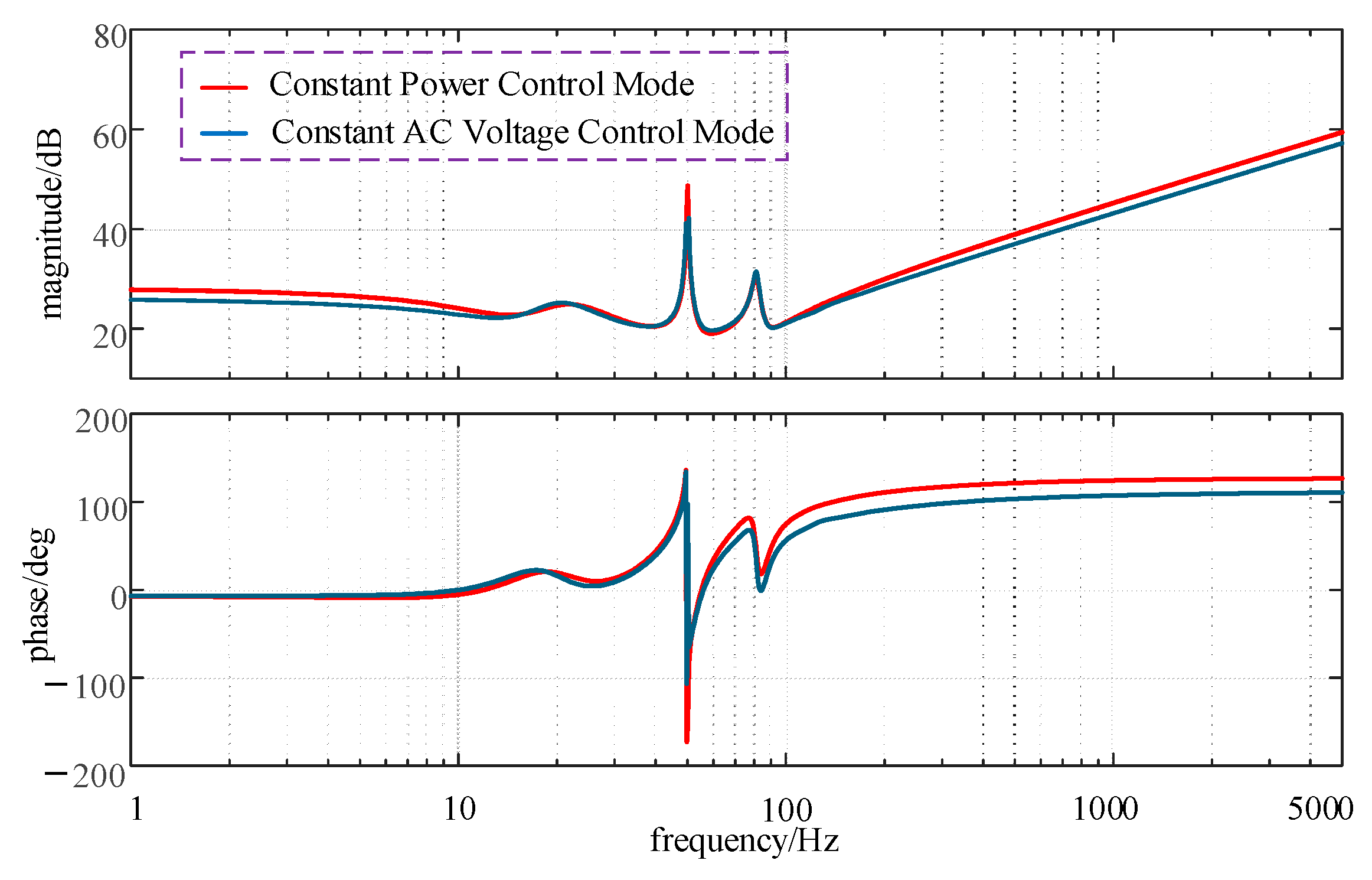
In order to select the control mode suitable for analyzing the high-frequency oscillation problem of the MMC-HVDC system, the impedance characteristics of the constant power control and constant AC voltage control modes are shown in Figure 3. The control parameters are the same except that the outer-loop control parameters are different.
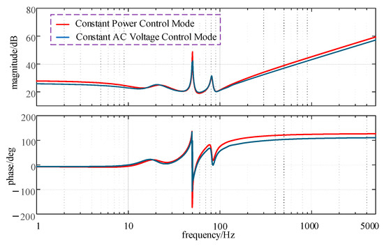
Figure 3.
Impedance characterization of MMC2 under different control modes.
Figure 3 shows that the impedance amplitude of MMC2 under constant AC voltage control shows no significant difference from that under constant power control. However, the damping characteristics of MMC2 under constant AC voltage control in the high-frequency band exhibit positive behavior, contrasting with the negative damping characteristics observed under constant power control. Therefore, this paper selects the constant power control mode of MMC2, which exhibits deeper negative damping, for further analysis.
3.2. Analysis of Oscillation Mechanism Based on Impedance Analysis Method
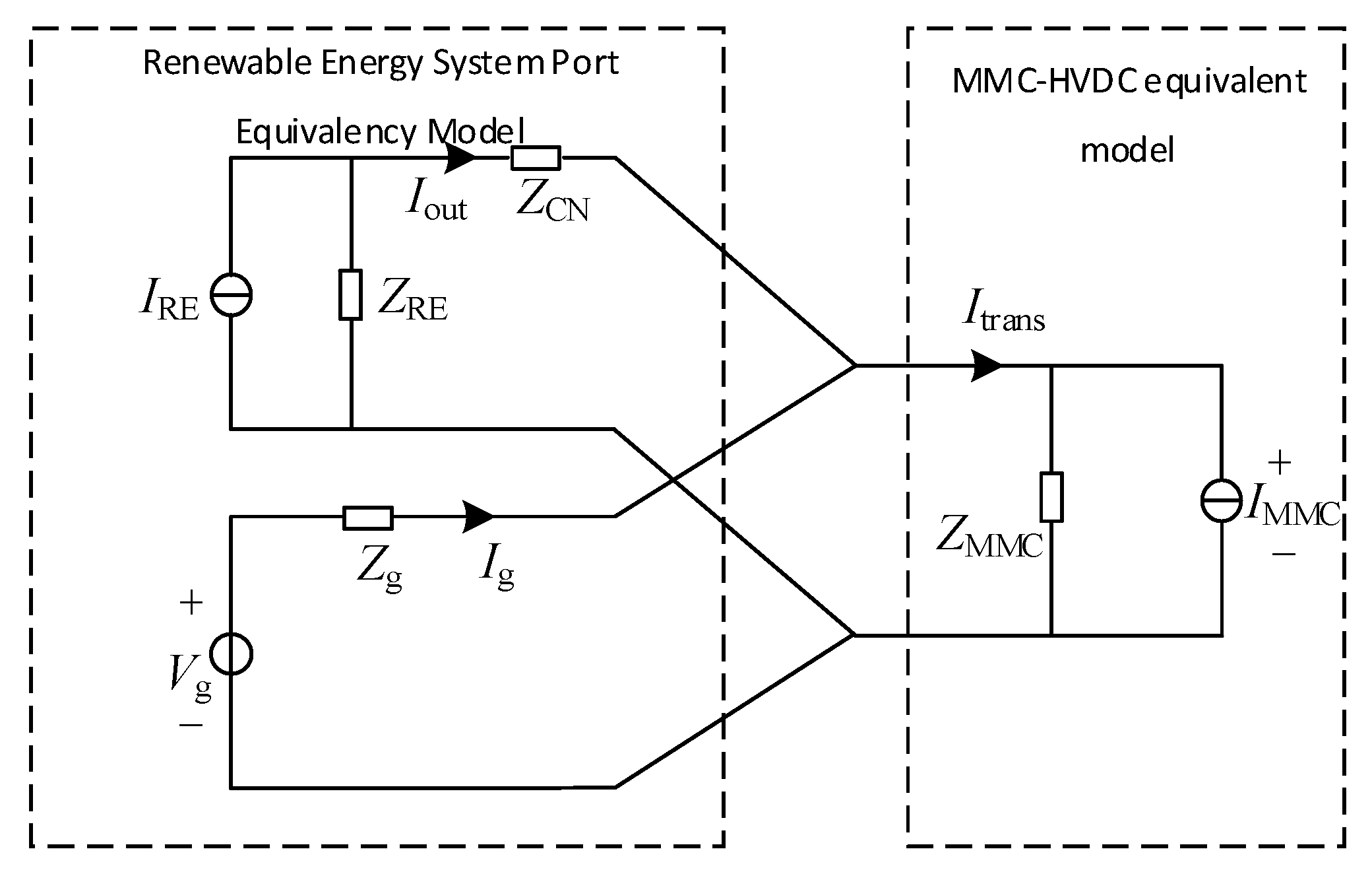
The renewable energy system is configured to emulate ideal current-source behavior IRE in parallel with its port impedance ZRE. The converter station of the MMC-HVDC system operates in constant power control mode, and the AC port can be equivalent to IMMC connected in parallel with its port impedance ZMMC. Under a weak grid background, the renewable energy systems integrated via MMC-HVDC transmission under weak grid conditions can be equivalent to a 3-port network composed of the renewable energy system port equivalency model, the MMC-HVDC equivalent model, and the AC grid, and the system stability is determined by all three together. Figure 4 details the operational equivalence framework. In the figure, Iout is the output current of the renewable energy generation; Ig is the port output current of the AC grid; and Itrans is the port current of the MMC-HVDC system.
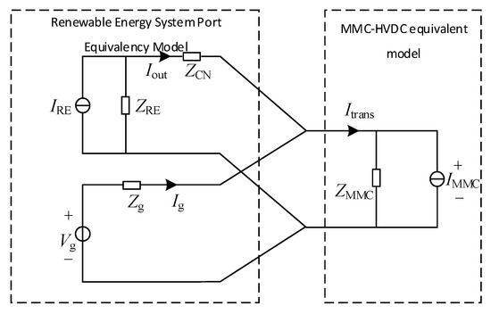
Figure 4.
Port equivalence modeling of renewable energy integration via MMC-HVDC transmission system under weak grid conditions.
According to the impedance analysis method, in addition to obtaining the port impedance ZRE of the renewable energy generation system, it is also necessary to obtain the parallel point impedance Zsys of the renewable energy generation system and AC power grid, and impedance modeling of the AC grid is similarly required.
Since this paper primarily focuses on the sending-end system of the MMC-HVDC transmission, the AC system is simplified by representing its impedance with an equivalent circuit consisting of a series RL circuit in parallel with a capacitor.
The AC-side stability of the MMC-HVDC sending-end system, as defined by Equation (29), is determined by the output impedance ratio between the renewable energy grid-connected system and the MMC-HVDC system. Applying the Nyquist stability criterion, compliance with Equation (30) reveals that this impedance ratio induces negative damping characteristics in the system, with oscillations emerging at the frequency corresponding to the intersection of the impedance magnitudes. To mitigate such oscillations, the control strategy must ensure that the phase difference between the system impedances remains within 180°, thereby stabilizing the system.
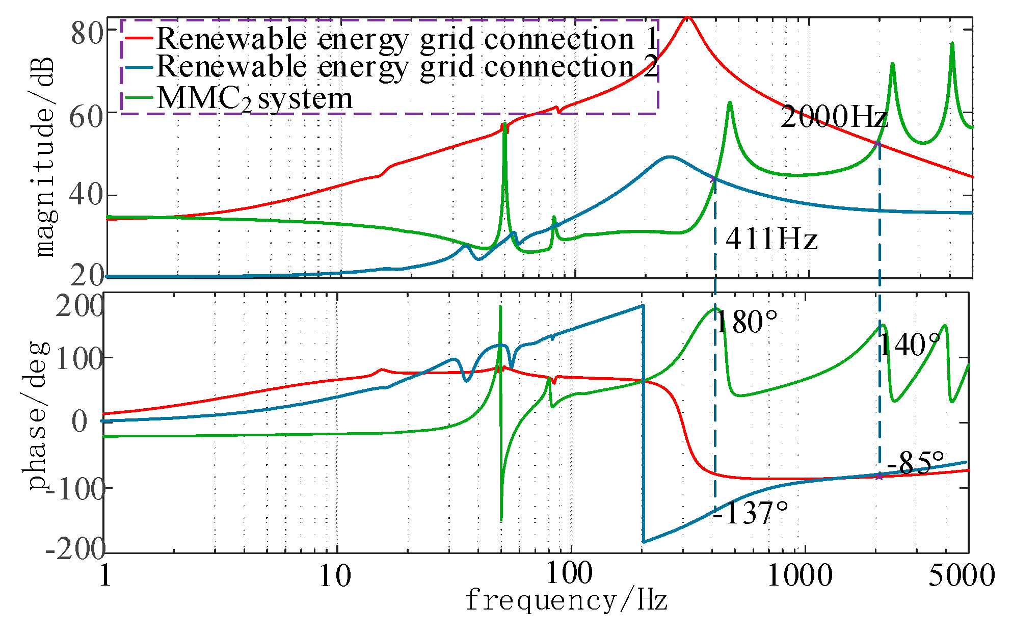
From Figure 5, it can be observed that after the renewable energy grid connection generation is transmitted via the MMC2, the impedances of the renewable energy generation grid connection system and the MMC2 transmission system under different grid conditions exhibit resonance points at 411 Hz and 2000 Hz, respectively, with negative damping characteristics. The system lacks sufficient amplitude/phase stability margins, indicating a risk of oscillations. The grid parameters are shown in Section 4.
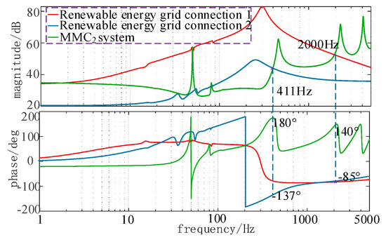
Figure 5.
Equivalent impedance of renewable energy integration via MMC2 under weak grid conditions.
3.3. MMC2 Impedance Sensitivity Analysis
According to the project requirements, this paper chooses to design the suppression strategy in the MMC2. Before proceeding, it is necessary to clarify the impact of MMC2’s impedance characteristics on the system. Since the multiple control loops of the MMC-HVDC system are coupled, they collectively influence its impedance characteristics. To analyze these effects, this section quantifies the contribution of each control loop by applying MMC impedance sensitivity analysis.
Impedance sensitivity is defined as the sensitivity of the system impedance to small changes in a specific parameter. A higher impedance sensitivity of a parameter indicates that fine-tuning that parameter will more drastically alter the system’s impedance characteristics. The absolute impedance sensitivity is defined as
where k is the influence factor; is the factor variation; s is the frequency domain identity; and Z is the MMC impedance.
To simplify the analysis of impedance characteristics, the absolute sensitivity is divided into magnitude sensitivity and phase-angle sensitivity , which are denoted as
where Im and Re are the imaginary and real parts of the sensitivity, respectively.
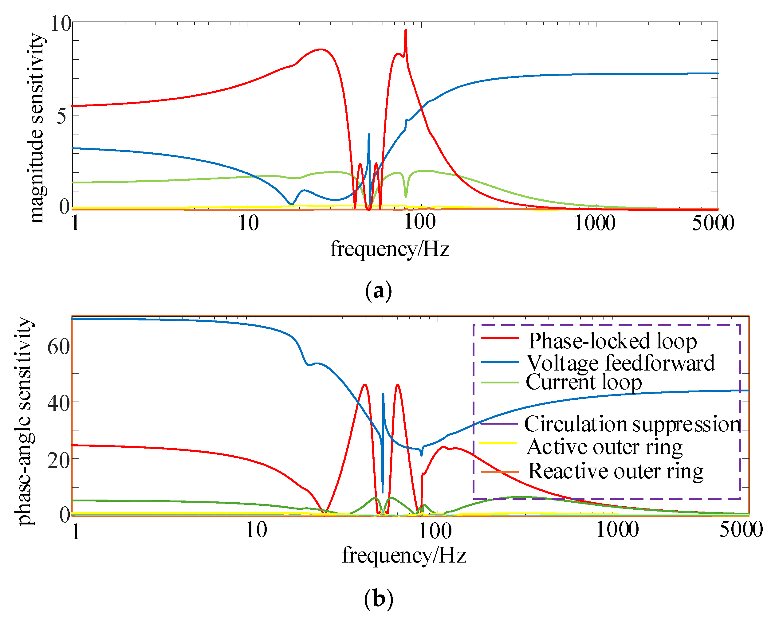
The impedance sensitivity curves of phase-locked loop, voltage feedforward coefficient, current loop, active outer loop, reactive outer loop, and loop current suppression on the MMC-HVDC system are given in Figure 6.

Figure 6.
Impedance sensitivity curves for each control parameter of MMC2: (a) impedance magnitude Sensitivity; (b) impedance phase-angle sensitivity.
In Figure 6, the voltage feedforward control has a greater effect on the impedance characteristics in the high-frequency band. The next largest impedance sensitivity is observed in the current inner loop. Across the full frequency range, the impedance sensitivities of the circulating current suppression, active outer loop, and reactive outer loop are relatively small. This indicates that the voltage feedforward coefficient and current inner loop significantly influence the impedance stability of MMC2 within the upper frequency band. Therefore, further research on the coordinated control of these two loops is critical.
4. Coordinated Current–Voltage Feedforward Oscillation Damping Method
The system exhibits vulnerability to high-frequency oscillations stemming from voltage feedforward dynamics and control loop latency. Addressing this instability necessitates impedance reshaping of the MMC-HVDC infrastructure to mitigate negative damping effects. A prevalent mitigation technique involves incorporating a low-pass filter into the feedforward path, which effectively stabilizes MMC2 operations but may inadvertently compromise impedance profiles across adjacent frequency ranges.
4.1. Control Analysis Based on Voltage Feedforward Control
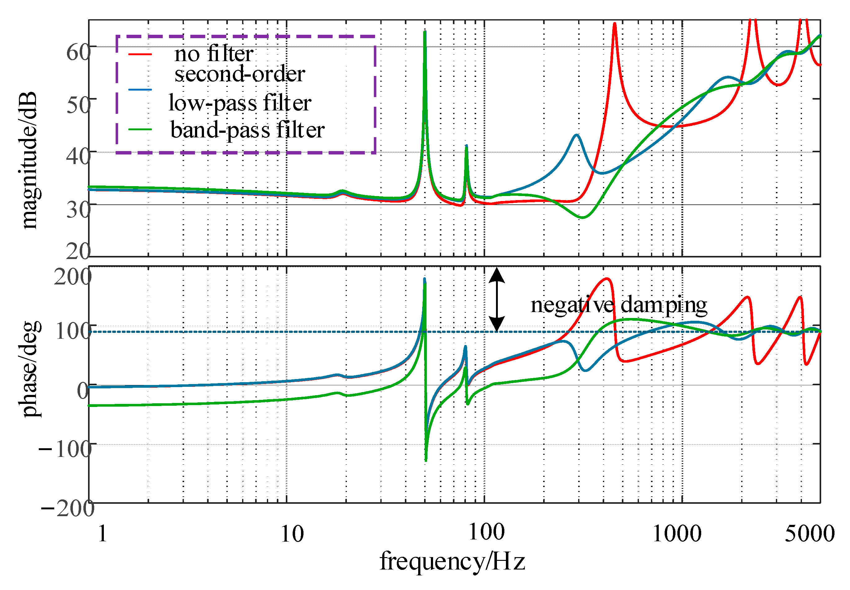
To address negative damping phenomena in the MMC-HVDC transmission system with renewable integration, this study introduces a second-order low-pass filter and a band-pass filter into the voltage feedforward architecture. The resultant impedance modifications are visualized in Figure 7.

Figure 7.
Impedance of MMC2 after additional voltage feedforward filters.
Second-order low-pass filters are more effective than single-order filters in reducing the impact of link delay on system performance.
where is the damping coefficient, , where is the cut-off frequency of the second-order low-pass filter.
The band-pass filter has a notch characteristic and is composed of a second-order low-pass filter cascaded with a second-order high-pass filter. is the damping coefficient; k is the gain of the band-pass filter; and and .
Based on the above analysis, the control mode modification requires modifying Equations (10) and (21) to the following equation.
Figure 7 demonstrates that the voltage feedforward with a band-pass filter offers superior damping performance compared to a second-order low-pass filter, highlighting the band-pass filter’s ability to enhance stability margins more effectively. However, while the addition of a band-pass filter to the voltage feedforward loop can alleviate negative damping characteristics in the high-frequency range of the MMC-HVDC sending-end system, it may trigger oscillations in other frequency bands, thereby failing to fully eliminate the negative damping frequency ranges in the system.
4.2. Oscillation Suppression Strategy for Modular Multilevel Converter—High-Voltage Direct Current Sending-End Systems via Coordinated Voltage Feedforward and Current Inner-Loop Control
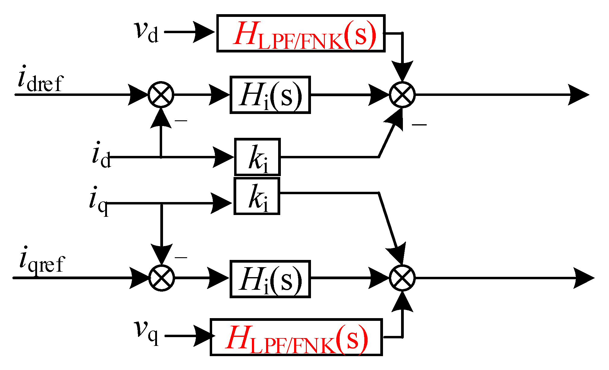
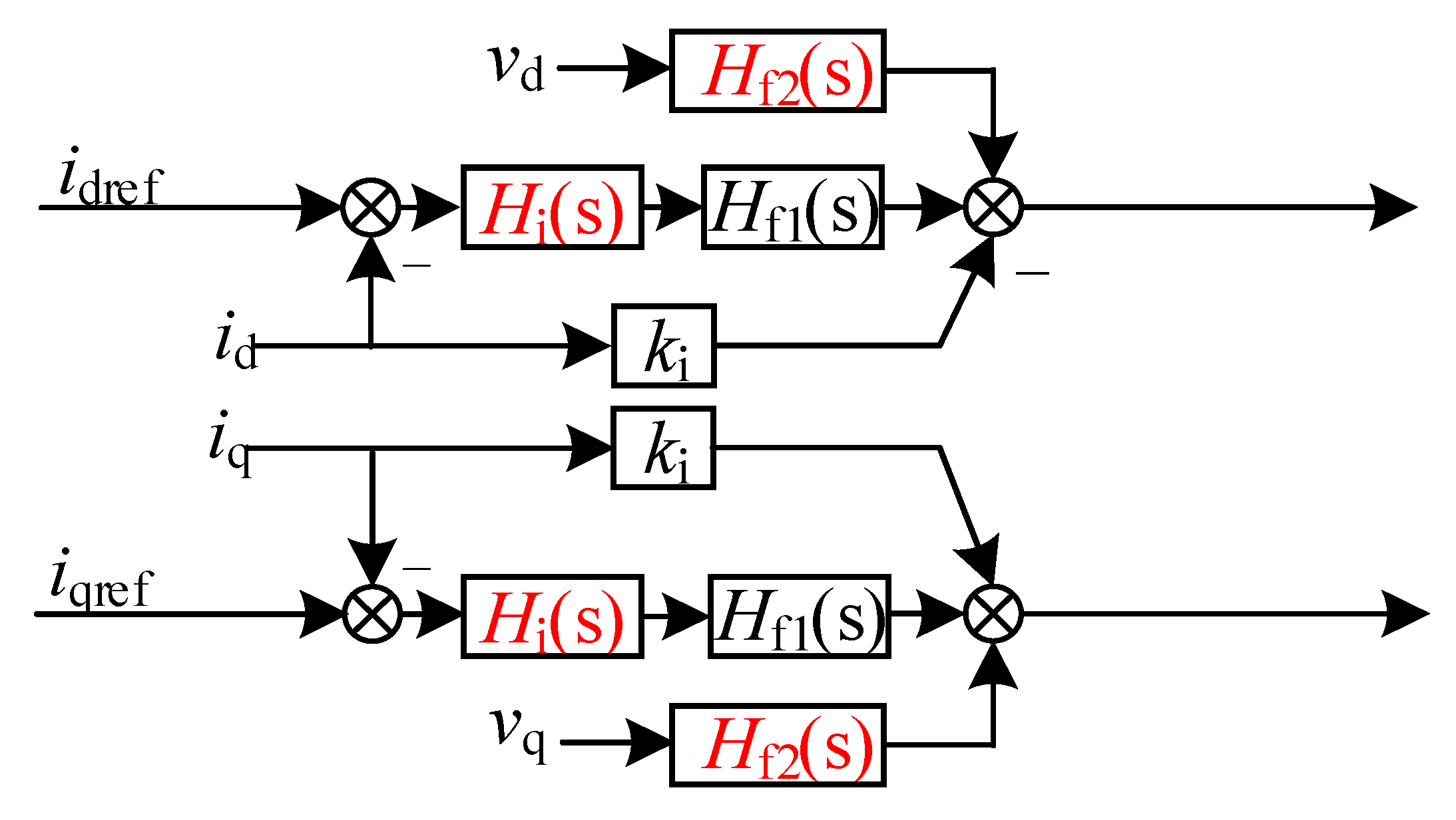
The sensitivity analysis reveals that the current inner loop also affects the impedance characteristics in this frequency band. To further eliminate negative damping frequency bands and prevent impedance reshaping from impacting other frequency ranges, the influence of the current inner loop is considered. A first-order low-pass filter is added to the voltage feedforward loop, while an overshoot and hysteresis corrector is implemented in the current inner loop.
A first-order low-pass filter is attached to the voltage feedforward link, and an overshooting hysteresis corrector is used in the current inner loop.
where , where is the cut-off frequency of the low-pass filter.
where is the damping factor, is the lower limit of the angular frequency of the overshoot and hysteresis corrector, and is the upper limit of the angular frequency of the overshoot and hysteresis corrector. By setting , the damping characteristics of the high-frequency band can be adjusted; through reasonable setting of and , we can achieve an control effect to cover the negative damping frequency range.
Based on the above analysis, the control mode modification requires modifying Equations (4), (10) and (21) to the following equation:
After integrating a band-pass filter into the voltage feedforward path and applying an overshoot hysteresis corrector to the current inner loop, the resultant impedance profile of the system is obtained, as illustrated in Figure 8 and Figure 9.

Figure 8.
Voltage feedforward additional filtering control.
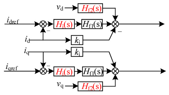
Figure 9.
Voltage feedforward and current loop synergistic control.
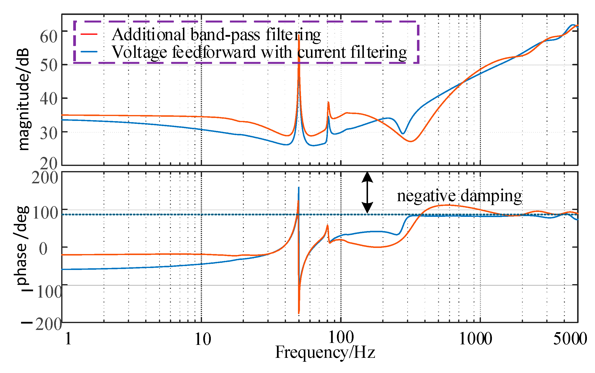
As shown in Figure 10, compared to the control strategy based solely on the voltage feedforward loop, the coordinated control of voltage feedforward and current inner loop provides better stability margins for the MMC-HVDC sending-end system. This approach further reduces the negative damping regions, thereby effectively improving the system stability.
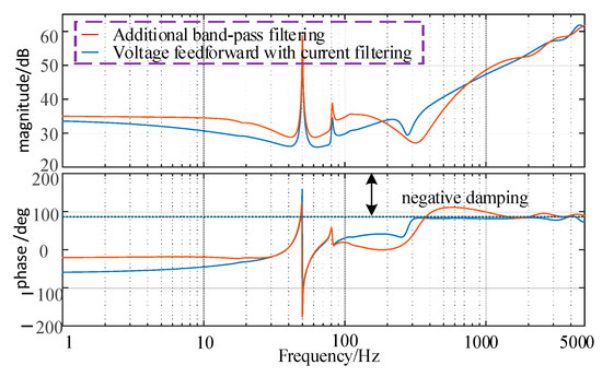
Figure 10.
Impedance of MMC2 after voltage feedforward and current loop synergistic control.
5. Verification of the Effectiveness of Oscillation Suppression Measures
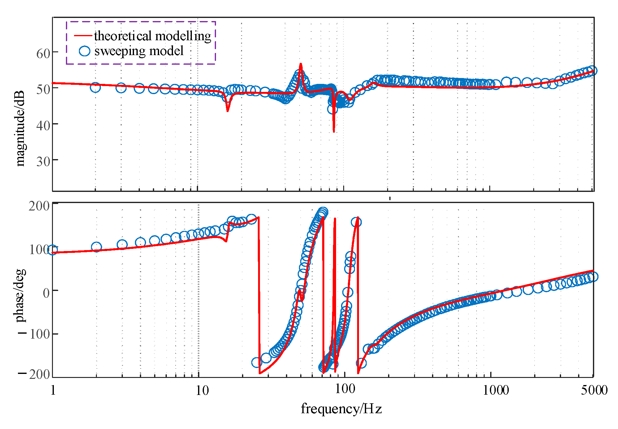
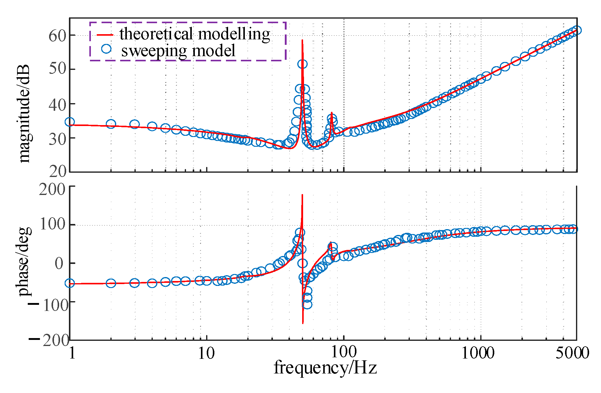
To validate the accuracy of the impedance model, electromagnetic transient model simulations were conducted for the control structure in Figure 2 using the parameters listed in Table 1. As shown in Figure 11 and Figure 12, the frequency-domain impedance spectrum results are in good agreement with theoretical predictions, validating the accuracy of the model.

Table 1.
MMC1 and MMC2 simulation model parameters.
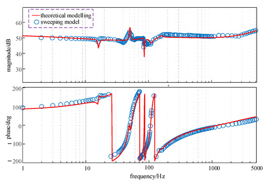
Figure 11.
MMC1 AC side impedance.
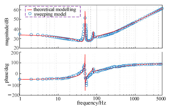
Figure 12.
MMC2 AC side impedance.
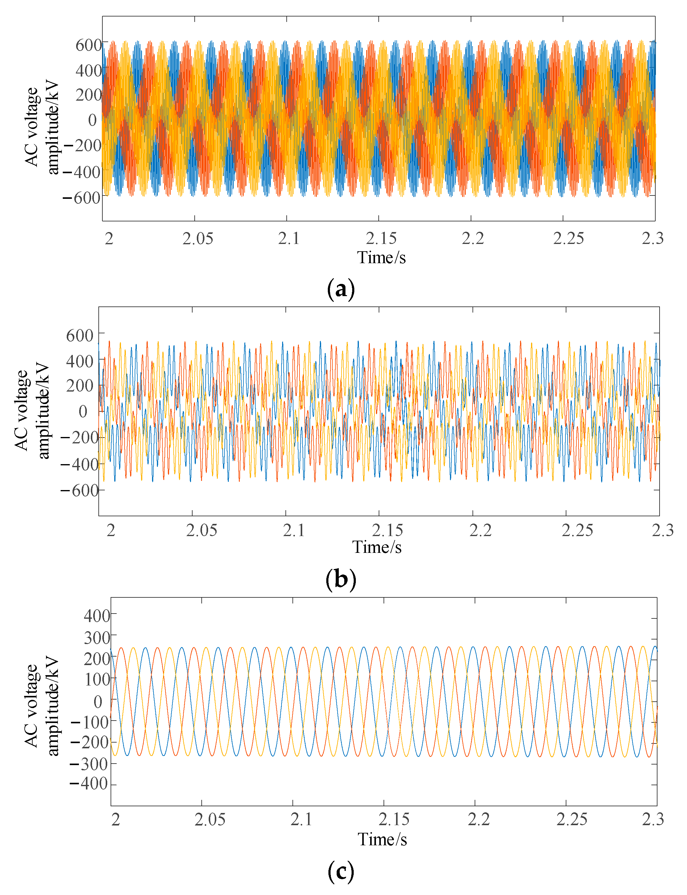
Case 1: When renewable energy is transmitted through the flexible DC transmission system, the AC grid is represented by an RLC-equivalent circuit with the following parameters: R = 0.5 Ω; L = 0.02 H; C = 0.7 μF. If no oscillation suppression measures are applied to the MMC-based flexible DC sending-end system, an oscillation phenomenon at approximately 2000 Hz occurs in the AC voltage of the sending-end converter.
As shown in Figure 13, when renewable energy is transmitted through the MMC-HVDC system, oscillations around 2000 Hz occur. After adding a second-order low-pass filter to the voltage feedforward loop, the oscillation phenomenon in the MMC2 system shifts to 400 Hz. However, with the addition of a band-pass filter, the oscillations in the MMC2 system are eliminated.
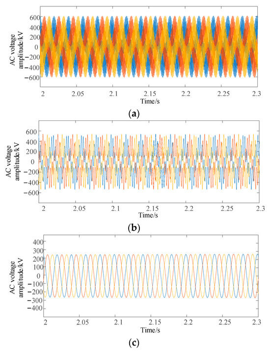
Figure 13.
AC voltage analysis for case 1: (a) no filter; (b) additional second-order low-pass filtering; (c) additional bandpass filters.
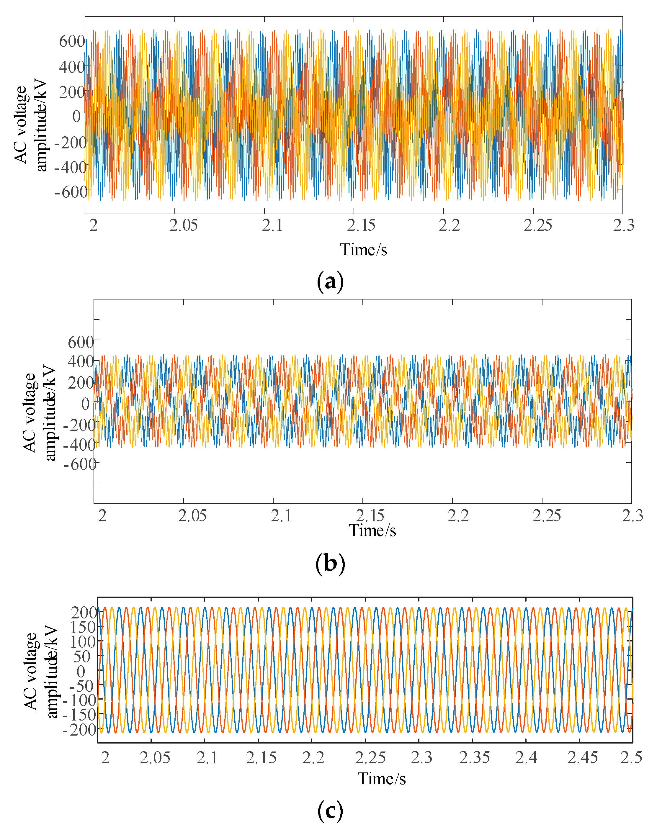
Condition 2: In the simulation verification of the control strategy incorporating a first-order low-pass filter in the voltage feedforward loop and a lead–lag compensator in the current inner loop, the AC grid impedance is modeled as an RLC equivalent circuit with the following parameters: R = 0.5 Ω; L = 0.02 H; C = 0.7 μF. However, the voltage feedforward with a low-pass filter control strategy fails to effectively suppress the oscillation phenomenon.
Based on Figure 14, when no filter is added, oscillations occur in the MMC2 system at 900 Hz. With the voltage feedforward and band-pass filter control strategy, oscillations shift to the 650 Hz range. However, when the coordinated control of DC voltage feedforward and current loop is implemented, the oscillations in the MMC-based MMC-HVDC sending-end system are fully suppressed.
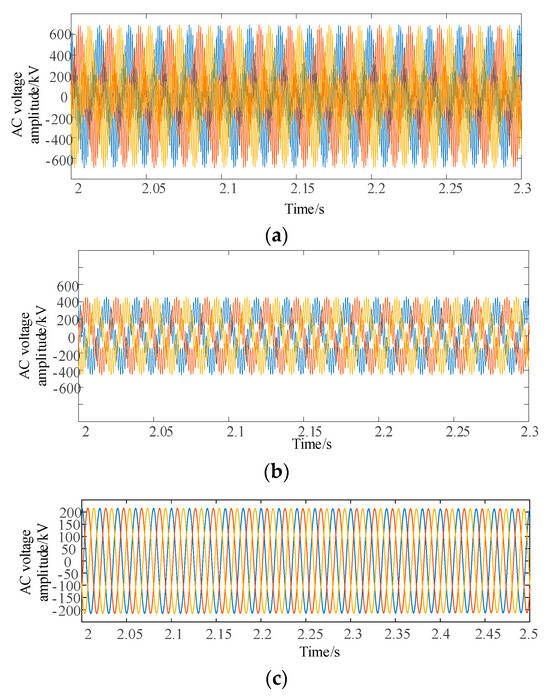
Figure 14.
AC voltage analysis for case 2: (a) no filter; (b) additional bandpass filters; (c) voltage feedforward additional current loop.
In conclusion, the coordinated voltage feedforward and current inner-loop suppression strategy effectively mitigates the oscillation phenomenon. The theoretical analysis and simulation results in this paper validate the effectiveness and generalizability of the proposed oscillation suppression strategy.
6. Results
This study develops AC-side impedance models for both the renewable energy grid-side converter and the MMC-HVDC sending-end converter through a multi-harmonic linearization approach. The impedance characteristics of the system under two different control modes are compared, and one is selected for analysis. The theoretical validity of these models is further confirmed via impedance frequency-sweep simulations. The stability influence patterns of different control loops are determined through the impedance sensitivity analysis method. Based on the voltage feedforward with an additional filter, a coordinated oscillation suppression strategy combining voltage feedforward and a current loop control is proposed. The effectiveness of the proposed suppression strategy is examined through theoretical analysis and simulation verification, and the following conclusions are obtained:
(1) The negative damping characteristics of MMC2 in constant AC voltage mode are more prominent than in constant power control mode. The degree of influence of each control loop of MMC2 on the stability of the grid-connected system is different, and the impedance sensitivity analysis shows that the voltage feedforward and current loop paths have a more obvious influence on the impedance stability of the MMC2 than the other control loop parameters, but the effect of improving the system stability in voltage feedforward add-on filter control mode is limited.
(2) The synergistic suppression strategy based on the voltage feedforward link and current inner loop can improve the negative damping bands of the MMC2 impedance, and the synergistic suppression strategy based on the voltage feedforward link and current inner loop can improve multiple negative damping bands and improve the stability margin of the system compared with the voltage feedforward add-on filter. Finally, the feasibility of the impedance control optimization method is demonstrated by simulation verification.
Author Contributions
R.D.: conceptualization, methodology, original writing, formal analysis, and validation. G.J.: conceptualization, methodology, and supervision. All authors have read and agreed to the published version of the manuscript.
Funding
This work was supported by the State Grid Jilin Electric Power Company Limited (China) under Contract No. 5100-202399363A-2-2-ZB, titled “Study on Dynamic Stability Mechanisms and Coordinated Control Technologies for Weak Outbound Systems with High Penetration of Renewable Energy Sources”.
Data Availability Statement
The original data presented in this study are included in the article. Further inquiries can be directed to the corresponding author.
Conflicts of Interest
The authors declare that this study received funding from SGCC Headquarters Science And Technology Project. The funder was not involved in the study design, collection, analysis, interpretation of data, the writing of this article or the decision to submit it for publication.
Abbreviations
| V1 | AC voltage fundamental frequency component magnitude |
| Vdc | DC voltage steady-state value |
| N | Number of bridge arm submodules |
| Csm | Submodule capacitance |
| Larm | Bridge Arm Inductors |
| Rarm | Bridge Arm Resistors |
| HV | DC Voltage Controller |
| Hq | Reactive power controller |
| Hi | Current inner-loop controller |
| Hc | Circulation Controller |
| Hpll | Phase-locked loop |
| Hp | Active power controller |
References
- Zhao, R.; Song, G. Research on Key Technology Points for MMC-HVDC System. PCIM Asia 2020. In International Exhibition and Conference for Power Electronics; Intelligent Motion, Renewable Energy and Energy Management: Shanghai, China, 2020; pp. 1–6. [Google Scholar]
- Mirsaeidi, S.; Dong, X.; Tzelepis, D.; Said, D.M.; Dysko, A.; Booth, C. A Predictive Control Strategy for Mitigation of ComMutation Failure in LCC-based HVDC Systems. IEEE Trans. Power Electron. 2019, 34, 160–172. [Google Scholar]
- Lesnicar, A.; Marquardt, R. An Innovative Modular Multilevel Converter Topology Suitable for a Wide Power Range. In Proceedings of the IEEE Bologna Powertech Conference, Bologna, Italy, 23–26 June 2003; pp. 272–277. [Google Scholar]
- Beddard, A.; Barnes, M.; Preece, R. Comparison of Detailed Modeling Techniques for MMC Employed on VSC-HVDC Schemes. IEEE Trans. Power Deliv. 2015, 30, 579–589. [Google Scholar]
- Guo, X.; Liu, B.; Mei, H.; Liu, J.; Yu, H.; Cao, F. Analysis and suppression of resonance between AC and DC systems in Chongqing-Hubei back-to-back HVDC project of China. Automat. Electr. Power Syst. 2020, 44, 157–167. [Google Scholar]
- Rygg, A.; Molinas, M. Apparent Impedance Analysis: A Small-Signal Method for Stability Analysis of Power Electronic-Based Systems. IEEE J. Emerg. Sel. Top. Power Electron. 2017, 5, 1474–1486. [Google Scholar]
- Sun, J.; Liu, H. Sequence Impedance Modeling of Modular Multilevel Converters. IEEE J. Emerg. Sel. Top Power Electron. 2017, 5, 1427–1443. [Google Scholar]
- Zhang, Y.; Chen, X.; Sun, J. Sequence Impedance Modeling and Analysis of MMC in Single-Star Configuration. IEEE Trans. Power Electron. 2020, 35, 334–346. [Google Scholar]
- Zhang, B.; Du, X.; Du, C.; Zhao, J.; Li, F. Stability Modeling of a Three-Terminal MMC-HVDC Transmission System. IEEE Trans. Power Deliv. 2022, 37, 1754–1763. [Google Scholar]
- Lyu, J.; Cai, X.; Molinas, M. Optimal Design of Controller Parameters for Improving the Stability of MMC-HVDC for Wind Farm Integration. IEEE J Emerg Sel Top Power Electron. 2018, 6, 40–53. [Google Scholar]
- Kwon, J.; Wang, X.; Blaabjerg, F.; Bak, C.L.; Sularea, V.-S.; Busca, C. Harmonic Interaction Analysis in a Grid-Connected Converter Using Harmonic State-Space (HSS) Modeling. IEEE Trans. Power Electron. 2017, 32, 6823–6835. [Google Scholar] [CrossRef]
- Xu, Z.; Li, B.; Han, L.; Hu, J.; Wang, S.; Zhang, S.; Xu, D. A Complete HSS-Based Impedance Model of MMC Considering Grid Impedance Coupling. IEEE Trans. Power Electron. 2020, 35, 12929–12948. [Google Scholar]
- Ji, K.; Tang, G.; Yang, J.; Li, Y.; Liu, D. Harmonic Stability analysis of MMC- based DC system using DC impedance model. IEEE J. Emerg. Sel. Top. Power Electron. 2020, 8, 1152–1163. [Google Scholar]
- Lyu, J.; Zhang, X.; Cai, X.; Molinas, M. Harmonic state-space based small-signal impedance modeling of a modular multilevel converter with consideration of internal harmonic dynamics. IEEE Trans. Power Electron. 2019, 34, 2134–2148. [Google Scholar]
- Pérez-Estévez, D.; Ríos-Castro, D.; Doval-Gandoy, J. Sensitivity-Based Impedance Modeling of AC Voltage-Controlled Converters. IEEE Trans. Ind. Appl. 2024, 60, 7125–7137. [Google Scholar] [CrossRef]
- Hao, Q.; Li, Z.; Gao, F.; Zhang, J. Reduced-order small-signal models of modular multilevel converter and MMC-based HVDC grid. IEEE Trans. Ind. Electron. 2019, 66, 2257–2268. [Google Scholar] [CrossRef]
- Lyu, J.; Zhang, X.; Huang, J.; Zhang, J.; Cai, X. Comparison of Harmonic Linearization and Harmonic State Space Methods for Impedance Modeling of Modular Multilevel Converter. In Proceedings of the 2018 International Power Electronics Conference (IPEC-Niigata 2018-ECCE Asia), Niigata, Japan, 20–24 May 2018; pp. 1004–1009. [Google Scholar]
- Zou, C.; Rao, H.; Xu, S.; Li, Y.; Li, W.; Chen, J.; Zhao, X.; Yang, Y.; Lei, B. Analysis of Resonance Between a VSC-HVDC Converter and the AC Grid. IEEE Trans. Power Electron. 2018, 33, 10157–10168. [Google Scholar]
- Man, J.; Chen, L.; Terzija, V.; Xie, X. Mitigating high-frequency resonance in MMC-HVDC systems using adaptive notch filters. IEEE Trans. Power Syst. 2022, 37, 2086–2096. [Google Scholar] [CrossRef]
- Zhu, J.; Hu, J.; Lin, L.; Wang, Y.; Wei, C. High-Frequency Oscillation Mechanism Analysis and Suppression Method of VSC-HVDC. IEEE Trans. Power Electron. 2020, 35, 8892–8896. [Google Scholar]
- Harnefors, L.; Yepes, A.G.; Vidal, A.; Doval-Gandoy, J. Passivity-based controller design of grid-connected VSCs for prevention of electrical resonance instability. IEEE Trans. Ind. Electron. 2015, 62, 702–710. [Google Scholar]

Disclaimer/Publisher’s Note: The statements, opinions and data contained in all publications are solely those of the individual author(s) and contributor(s) and not of MDPI and/or the editor(s). MDPI and/or the editor(s) disclaim responsibility for any injury to people or property resulting from any ideas, methods, instructions or products referred to in the content. |
© 2025 by the authors. Licensee MDPI, Basel, Switzerland. This article is an open access article distributed under the terms and conditions of the Creative Commons Attribution (CC BY) license (https://creativecommons.org/licenses/by/4.0/).