Abstract
This study proposes an improved bidirectional dynamic jump point search (JPS) algorithm to address key challenges in mobile robot path planning, including excessive node expansions, poor path smoothness, safety concerns, and extended search times. The core novelty of this algorithm lies in the introduction of adaptive weight coefficients in the heuristic function and dynamic constraint circles to optimize node expansions. Specifically, the adaptive heuristic function dynamically adjusts the weight coefficients based on the current position relative to the target point, significantly accelerating path searches while ensuring accuracy. Additionally, a dynamically constrained circle is introduced, which defines an adaptive search region, prioritizing node expansions within its boundary and effectively reducing unnecessary searches. Moreover, the jump point selection rules have been optimized to eliminate hazardous nodes and further improve path safety and practicality. Simulation tests conducted on grid maps with varying complexities clearly demonstrate that the proposed algorithm considerably reduces search times by up to 66.27% compared with conventional A*, traditional JPS, and bidirectional JPS methods. Finally, physical mobile robot experiments further validate the effectiveness and real-world applicability of the proposed algorithm.
1. Introduction
Path planning is essential in modern automation technologies, particularly for mobile robots and autonomous systems in applications such as autonomous driving vehicles [1], autonomous navigation robots [2,3], logistics management, and transportation industries [4]. Global path planning [5], operating in known environmental conditions, employs predefined environmental models and path planning algorithms to determine an optimal or near-optimal route from a starting point to a goal point while avoiding all obstacles and meeting performance criteria. By contrast, local path planning [6] dynamically adjusts an unmanned aerial vehicle’s trajectory using real-time sensor information to navigate unpredictable environments with moving obstacles. Currently, common path planning algorithms [7] comprise the Dijkstra algorithm [8,9], A* algorithm [10], ant colony optimization algorithm [11], particle swarm optimization algorithm [12], genetic algorithm [13], simulated annealing [14], artificial potential field method [15], and rapidly-exploring random tree algorithm [16].
The traditional A* algorithm is widely used in path planning but suffers from issues such as excessive node expansions and low search efficiency in complex environments. To overcome the limitations of the A* algorithm, reference [17] introduced the jump point search (JPS) algorithm, which preserves the heuristic function of A* while enhancing path planning efficiency by pruning expanded nodes. However, identifying jump points can be computationally demanding, particularly in complex environments with a high obstacle density. Reference [18] introduced a polygon-based pruning algorithm, PO-JPS, to minimize the search space and decrease the planning time. However, this method may lead to rigid paths and local optimal solutions, particularly in environments with complex obstacles. Reference [19] proposed a bidirectional JPS algorithm that addressed excessive node expansions, long search times, and large turning angles in the A* algorithm. While this approach reduced both search times and node expansions, it encountered limitations in certain scenarios where forward and backward searches failed to converge. This issue arose when certain obstacles caused the two search fronts to expand separately from opposite sides, resulting in non-overlapping paths. Reference [20] addressed potential safety hazards that might arise during real deployments and introduced an optimized JPS algorithm incorporating path-safety inflation. This approach utilized adaptable inflation factors to accommodate complex and variable environments. Reference [21] proposed a safety-based dynamic JPS algorithm to mitigate robot collisions resulting from control and localization errors in complex environments, establishing a safe distance between obstacles and robots by adjusting a node–domain matrix of variable size. Reference [22] refined the JPS algorithm from a visual perspective, seamlessly integrating visual adaptive Monte Carlo localization with pruning strategies. This optimization yielded promising results in automated guided vehicle applications. Reference [23] tackled the challenges associated with the JPS algorithm in large-scale maps, specifically addressing issues related to blind search ranges and excessive node expansion, which resulted in lengthy search times and high memory usage due to invalid searches. By introducing standard central vectors and constrained areas, they significantly enhanced the algorithm’s performance in large-scale maps.
To address the problems associated with excessive jump points and node expansions, poor path smoothness and safety, and extended search times in the above-mentioned algorithms, this study proposes an improved bidirectional dynamic JPS algorithm. The proposed algorithm dynamically defines forward and backward expansion targets while incorporating an adaptive heuristic function to significantly enhance search efficiency. Furthermore, the jump point selection mechanism is optimized to effectively circumvent hazardous nodes, thereby enhancing path safety and practicality. Moreover, the algorithm enhances the bidirectional dynamic JPS algorithm by introducing a dynamic constraint circle, which restricts the expansion region within the circle to further improve algorithm performance. Finally, to assess its effectiveness and practicality, the improved algorithm was tested through simulation-based experiments and physical trials with mobile robots.
2. Basic Algorithms and Their Limitations
2.1. A* Algorithm
The A* algorithm is an advanced heuristic search tool designed to determine the shortest traversal path from the starting point to the target point within a graph. By integrating the advantages of both Dijkstra’s algorithm and the best-first-search algorithm, A* optimizes pathfinding through a cost estimation function to evaluate the total cost required to traverse from the starting point to the goal point. The cost estimation function utilized by the A* algorithm is defined as follows:
where signifies the current node; refers to the estimated total cost from the starting node through node to the target node; indicates the actual cost from the starting node to node ; and implies the heuristic estimate of the cost from node xxx to the target node. Common heuristic functions utilized in search algorithms include the Euclidean, Manhattan, and Chebyshev distances. During the search process, the algorithm assigns higher priority to nodes with smaller values, and lower indicates a more optimal path.
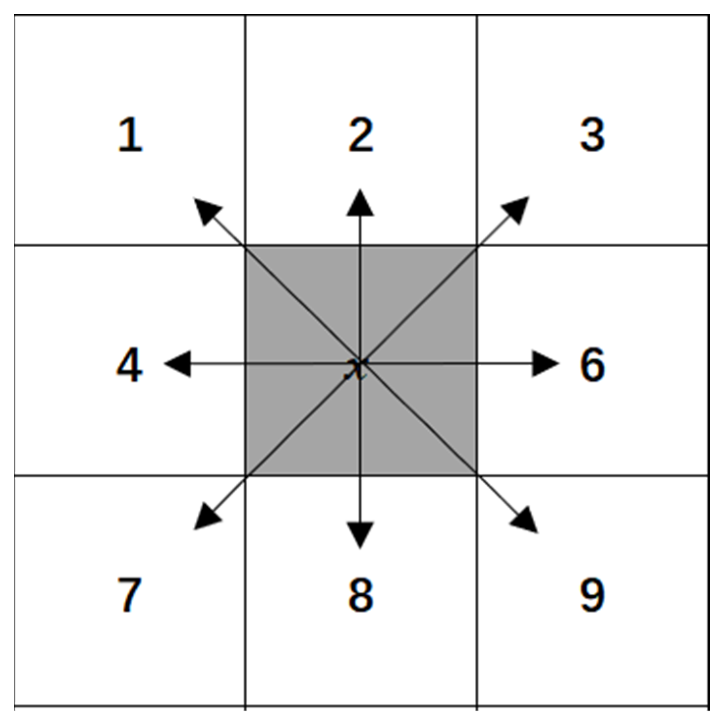
During the searching process, the A* algorithm selects the node with the lowest value from the open list and designates it as the current node. It then expands its search by exploring the surrounding eight directions, as shown in Figure 1.
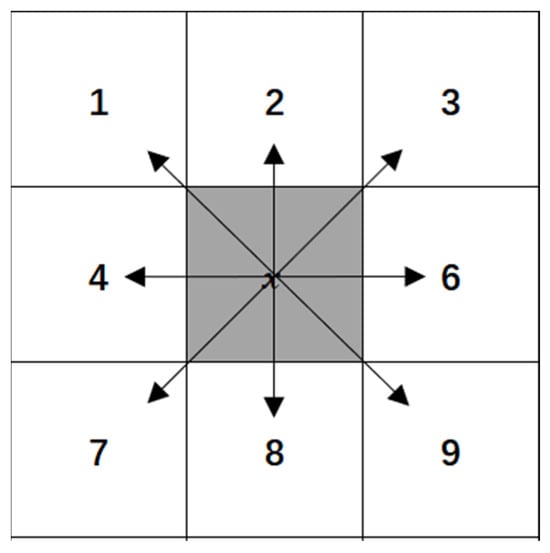
Figure 1.
Search directions.
2.2. JPS Algorithm
Instead of blindly expanding all reachable neighboring nodes, the JPS algorithm enhances the A* algorithm by selectively expanding nodes that alter the path’s direction, referred to as “jump points”. By minimizing the search space’s node count, JPS significantly accelerates the pathfinding speed. The fundamental feature of the JPS algorithm lies in its rules for identifying jump points. In grid-based maps, the JPS algorithm expands in two directions: straight and diagonal.
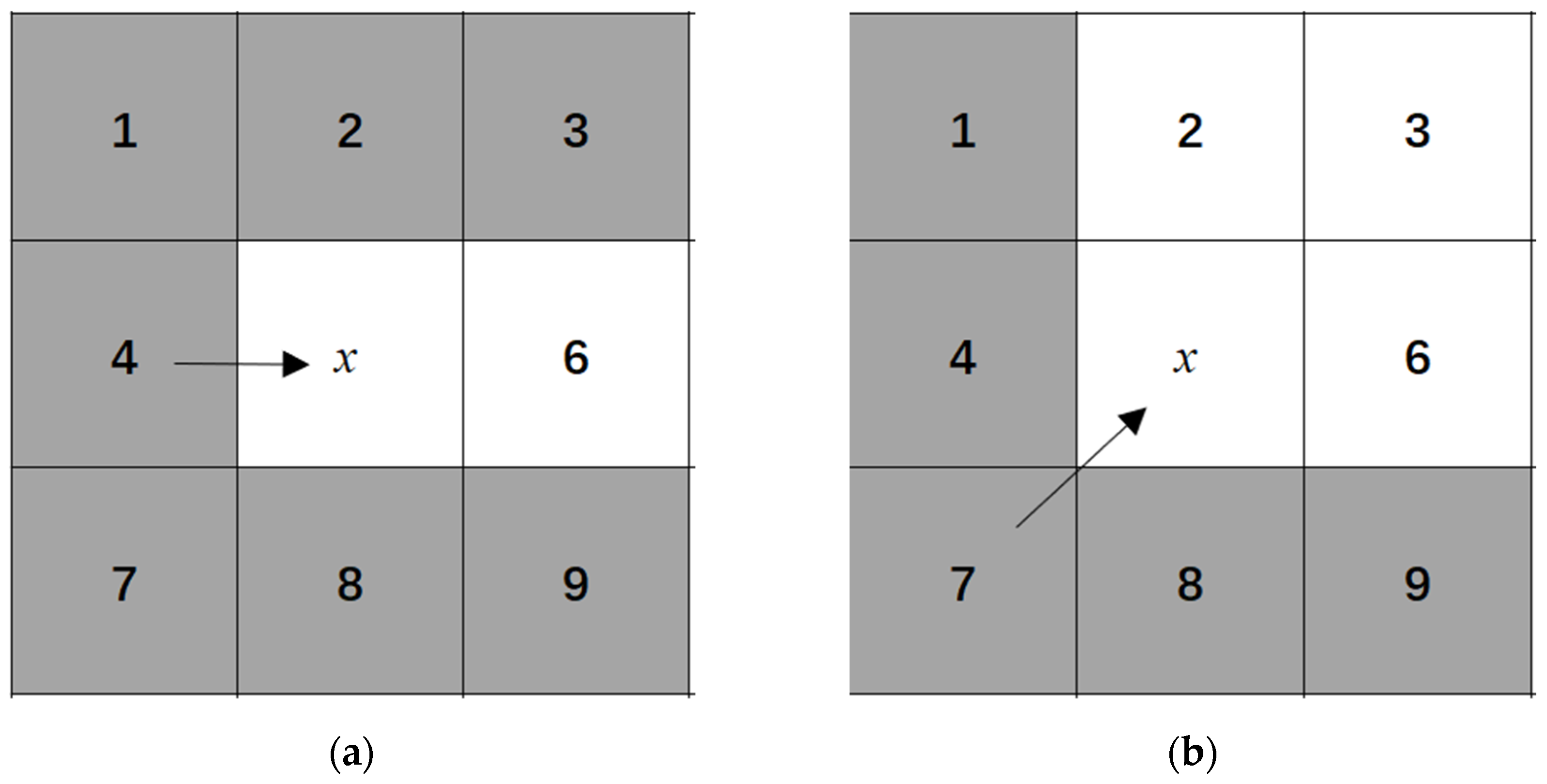
When there are no obstacles surrounding the node, as shown in Figure 2a,b, node 4 signifies the parent node, node x indicates the current node, and node 6 represents an unexpanded node. For a straight-direction search, the shortest possible path from nodes 4 to 6 that passes through node x is the shortest possible route, thereby making node 6 a “natural neighbor”. By contrast, traveling from node 4 to the gray-colored nodes—1, 2, 3, 7, 8, and 9—without passing through node x leads to a shorter path. Therefore, these gray nodes can be excluded from further consideration as they are deemed unnecessary. Similarly, in diagonal-direction searches, nodes 2, 3, and 6 serve as natural neighbors, while nodes 1, 4, 8, and 9 are considered unnecessary nodes.
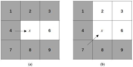
Figure 2.
Jump point selection rules around nodes in obstacle-free areas. (a) Straight direction; (b) Diagonal direction.
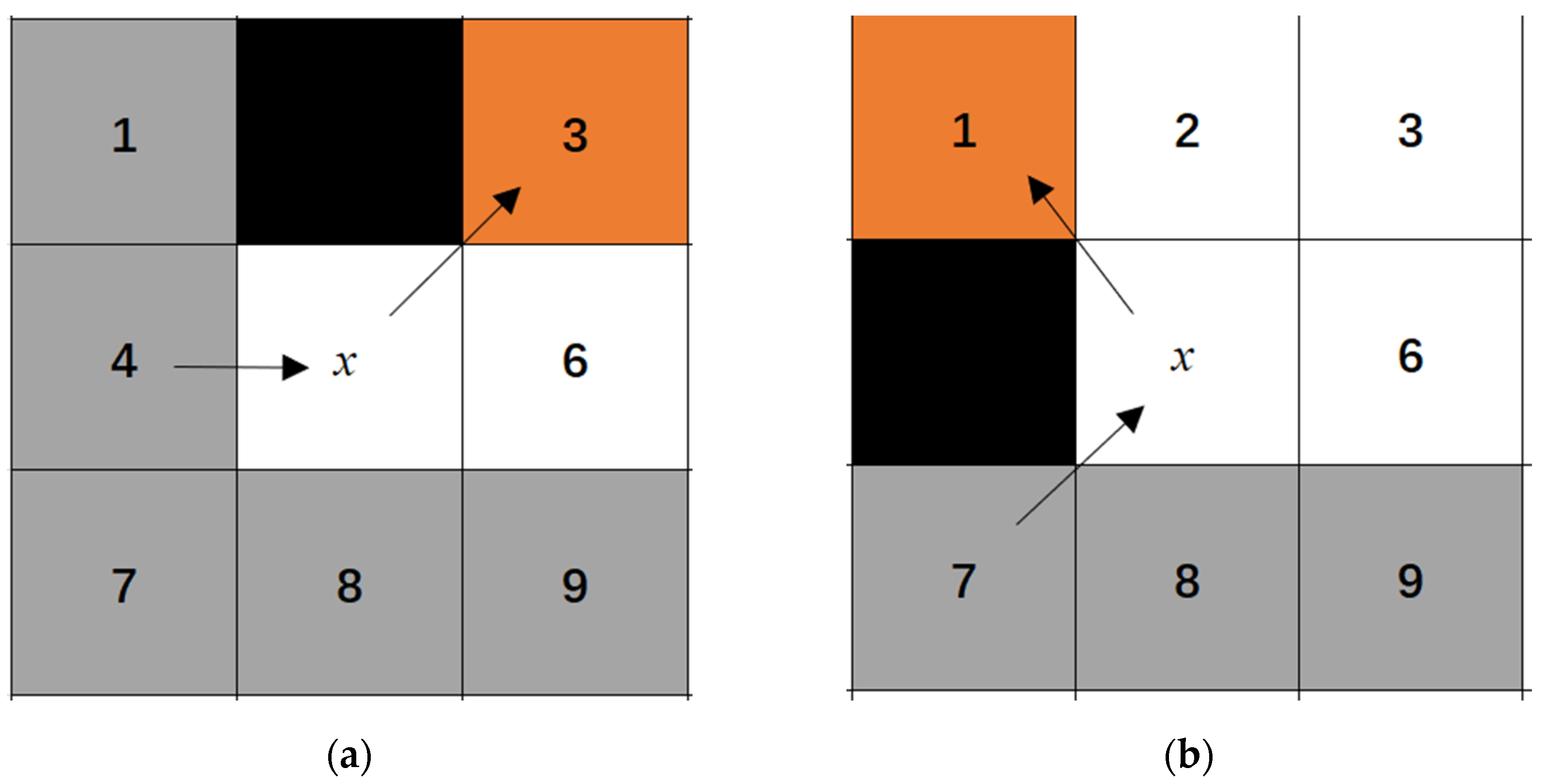
When obstacles are present around the node, as illustrated in Figure 3a,b, node 4 serves as the parent node, while node x represents the current node. The black squares indicate the locations of obstacles. In a straight-direction search scenario, the shortest path from node 4 to 3 must inevitably pass through node x. Consequently, node 3 is classified as a forced neighbor. Similarly, in the diagonal-direction search scenario, node 1 is also classified as a forced neighbor.

Figure 3.
Jump point selection rules around nodes with obstacles. (a) Straight direction; (b) Diagonal direction.
For the scenarios outlined above, the conditions for identifying jump points are as follows:
- If node x serves as either the start or goal node, it is designated as a jump point;
- If node x possesses at least one forced neighbor, then it qualifies as a jump point;
- In diagonal-direction searches, node x is recognized as a jump point if it has a jump point in a straight-direction search.
The JPS algorithm employs the same cost estimation function as the A* algorithm.
However, it has several limitations. While JPS optimizes search efficiency by minimizing the number of nodes that must be checked during searches, its performance on large maps is hindered by extensive preprocessing. This preprocessing stage requires examining each node within the map to calculate jump points and obstacle information in multiple directions. As a result, it can be computationally expensive, leading to prolonged preprocessing times and substantial memory usage. In addition, paths planned by JPS may lack smoothness, making it difficult for mobile robots to effectively avoid hazardous nodes. Moreover, inaccurate heuristic functions can deviate from the optimal path or cause the search process to become trapped in local optima.
2.3. Bidirectional JPS Algorithm
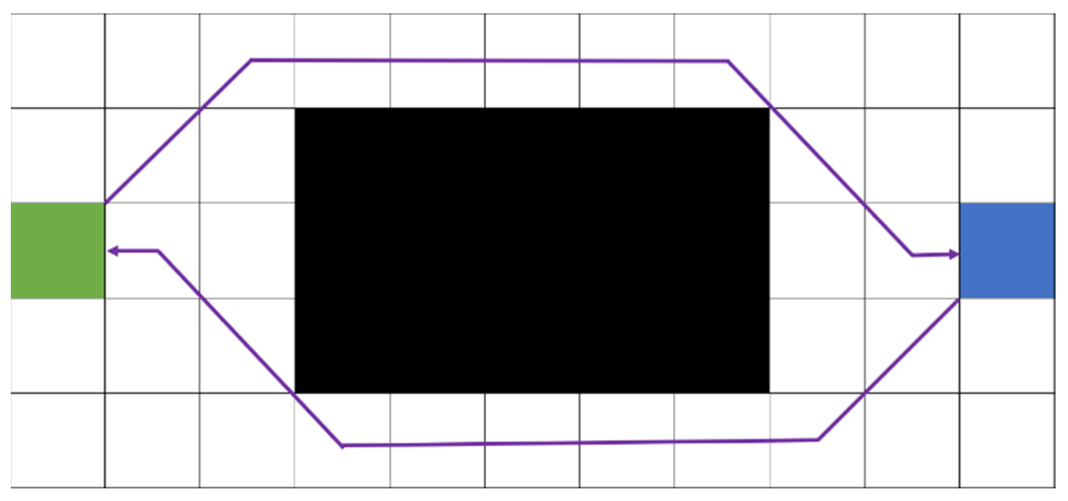
The bidirectional JPS algorithm enhances the conventional JPS by initiating searches from the start and goal nodes simultaneously. These searches progress until they converge at some intermediate point, significantly reducing the overall search space. In theory, this approach attains nearly twice the efficiency of the traditional JPS algorithm. However, in practical applications, certain challenges may hinder the direct intersection of the forward and backward search processes. Instead of converging seamlessly, these searches may expand jump points independently from opposite sides of an obstacle, preventing their respective search paths from merging smoothly, as illustrated in Figure 4. This non-overlapping path scenario can considerably reduce the algorithm’s efficiency and accuracy as additional computations become necessary to evaluate whether the two search directions can converge at a common point to derive the optimal path.
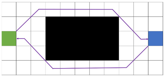
Figure 4.
Non-overlapping scenario based on forward and backward searches in the bidirectional jump point search (JPS) algorithm.
3. Improved Bidirectional JPS Algorithm
3.1. Improvement in the Heuristic Function
Refining the heuristic function enhances search efficiency, optimizes path quality, and improves adaptability to complex environments. By providing a more precise evaluation of node priorities, this refinement minimizes redundant node expansions and expedites path discovery. This study presents a heuristic function based on the Euclidean distance, as defined in Equation (2). To improve the accuracy of the heuristic estimate, an adaptive weighting coefficient (1 + sin ), greater than or equal to 1, is introduced, as shown in Equation (3). As the algorithm progresses and the robot moves closer to the target, the distance α gradually decreases, causing the weighting coefficient to gradually approach 1, thus ensuring accuracy and optimality in the final path selection.
The enhanced cost function is expressed as follows:
where indicates the distance from the mobile robot’s current position to the goal point, and implies the distance from the start point to the goal point. At the initial stages of the search, when the current node is distant from the goal, the heuristic function tends to underestimate the actual value. Therefore, by increasing the weighting coefficient, the heuristic estimate is adjusted upward, leading to a more efficient search process and enhanced computational speed. However, as the current node approaches the goal, a more precise heuristic estimate becomes indispensable to determining the optimal path. To achieve this end, the weighting coefficient is gradually reduced, thereby reducing the heuristic value and slowing down the search to explore more nodes. Initially, remains large, and remains constant; the term sin decreases gradually as decreases with the progression of the algorithm. Resultantly, the behavior of follows this theoretical principle, substantially enhancing the algorithm’s overall pathfinding efficiency.
3.2. Improvement in Jump Point Selection Rules
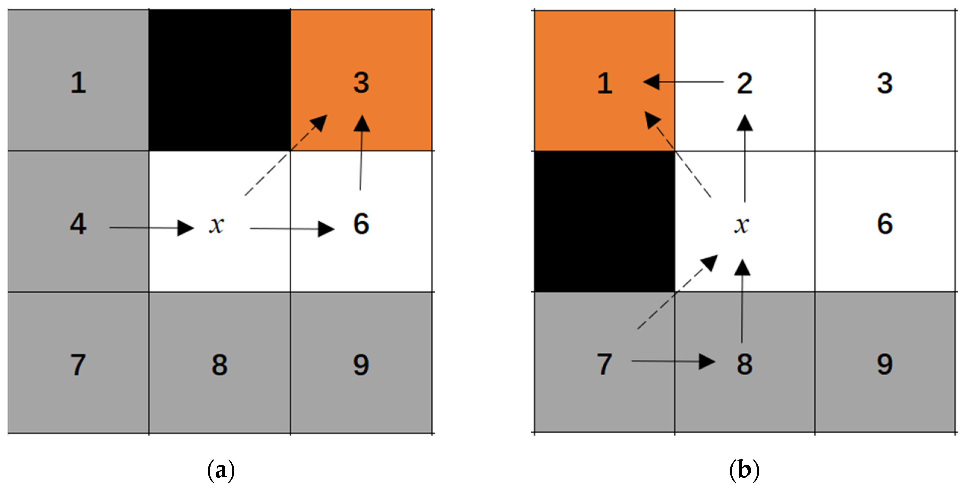
To address potential collision risks between mobile robots and obstacles in the original JPS algorithm during path planning, this study introduces an improved approach to jump point selection rules. The search directions for jump points continue to be categorized as straight and diagonal. If a node is not surrounded by obstacles, the original selection rules remain unchanged. However, in cases where obstacles exist around a node, the jump point selection process is refined through the following improvements.
Figure 5a,b illustrate the process of straight-direction searches. In the original path, denoted by the dashed line, node 4 (the parent node) reaches node 3 (forced neighbor) by passing through node x (a designated jump point). However, in the optimized path, represented by the solid line, node 4 connects to node 3 via node 6, thereby eliminating the possibility of direct diagonal access along the dashed line. This modification ensures the avoidance of hazardous nodes. Specifically, node x is no longer recognized as a jump point; instead, node 6 assumes this role. Similarly, during searches along the diagonal direction, nodes 2 and 8 are identified as jump points.
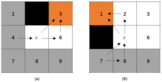
Figure 5.
Enhanced jump point selection rules. (a) Straight direction; (b) Diagonal direction.
By improving the criteria for selecting jump points, the issue posed by multiple hazardous nodes in the traditional JPS algorithm is effectively resolved. This improvement ensures a suitable safety distance is consistently maintained between the mobile robot and surrounding obstacles, thereby greatly enhancing path-planning safety. This enhancement significantly improves the reliability of the path-planning system by systematically removing hazardous nodes—thereby reducing potential risks encountered by mobile robots. In addition, it broadens the coverage of jump points, optimizing the algorithm’s ability to efficiently target search areas and accelerate the overall search speed.
3.3. Dynamic Definition of Target Points
In the bidirectional JPS algorithm, jump point searches from both forward and backward directions may result in a scenario where nodes fail to connect, leading to non-overlapping paths. To address this issue, target points can be dynamically adjusted using an alternating search strategy during the bidirectional path optimization process. This strategy continuously updates the target points throughout the search process, facilitating effective intersections between forward and backward expansions.
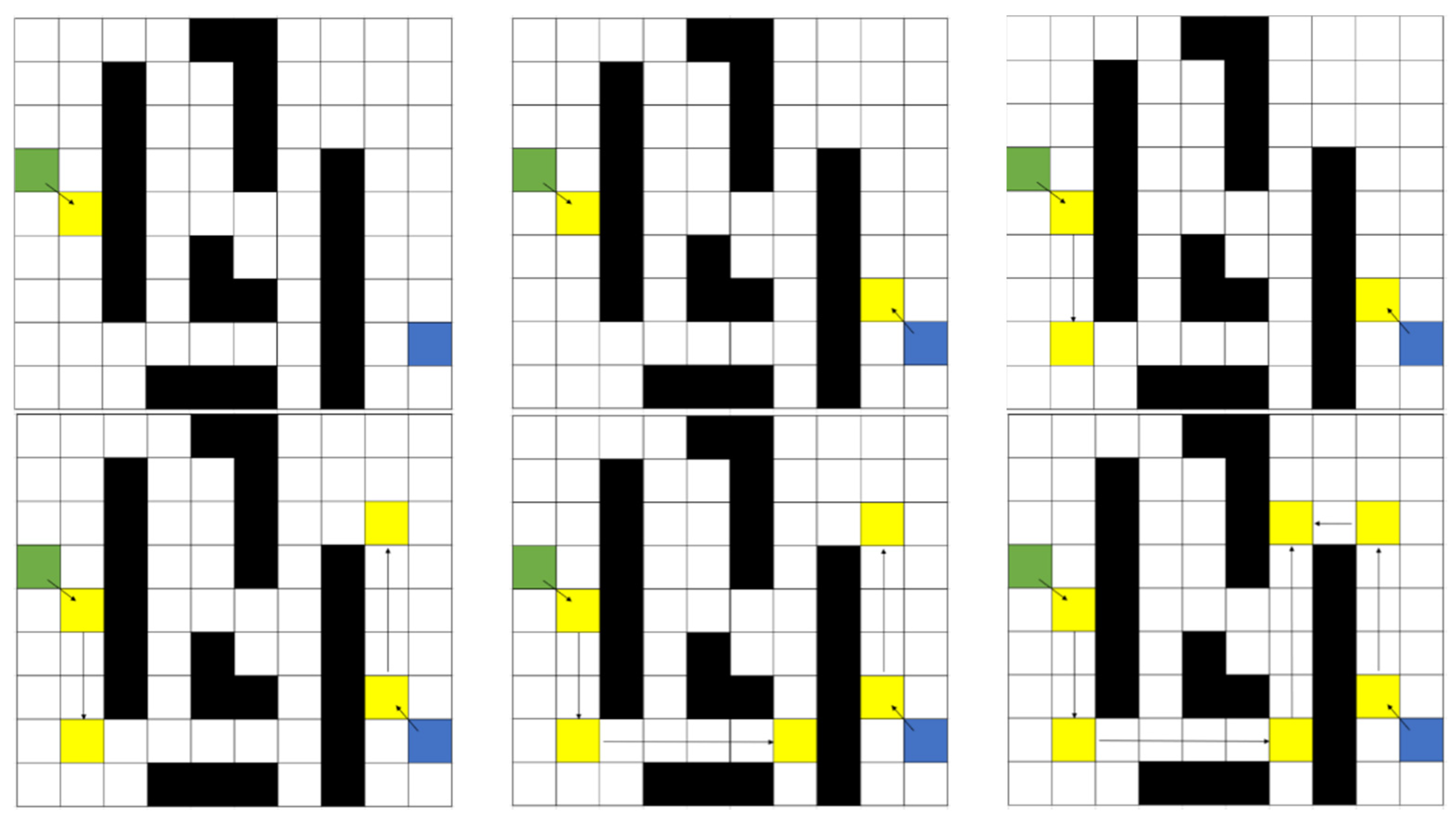
Specifically, the bidirectional JPS algorithm first performs a forward-direction search, which progresses until the jump point with the lowest cost is located. Subsequently, the algorithm transitions to a backward-direction search, designating the most recently identified forward jump point—rather than the original starting node—as the new target. This backward search continues until another jump point is located. Once identified, the algorithm resumes the forward search, treating the newly identified backward jump point as the target. This alternating process continues iteratively. The bidirectional JPS algorithm enhances the efficiency of pathfinding by dynamically redefining target points that alternate between forward and backward searches. A valid path is confirmed when jump points from both search directions intersect, signifying the successful connection of the route.
Figure 6 provides a comprehensive pathfinding procedure in the bidirectional JPS algorithm with dynamically defined target points: green squares indicate the start node; blue squares refer to the goal node; black squares imply obstacles; and yellow squares imply jump points traversed during the search.
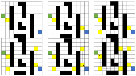
Figure 6.
Path optimization workflow in the bidirectional JPS algorithm.
This bidirectional JPS algorithm employs an alternating search strategy that effectively addresses the issues related to non-converging nodes failing to meet and non-overlapping paths while significantly enhancing the path’s search efficiency. During each alternating search step, the algorithm dynamically adjusts the search direction and target in response to the identified jump points, enabling a more flexible and intelligent search process. In addition, by continuously refining the search based on the current optimal jump point at any given iteration, the algorithm efficiently converges on the globally optimal path.
3.4. Introducing the Dynamic Constraint Circle
A dynamic constraint circle is introduced to optimize the efficiency of the bidirectional JPS algorithm. This circle is centered at the midpoint between the nodes with the lowest costs in the forward and backward expansion directions. Its radius is determined as half of the product of the circle expansion coefficient () and the distance separating these two nodes. In this study, the dynamic constraint circle is defined as follows:
where a = (x1 + x2)/2 refers to the horizontal coordinate of the circle center, with x1 and x2 representing the horizontal coordinates of the minimal-cost nodes from forward and backward expansions, respectively. b = (y1 + y2)/2 indicates the vertical coordinate of the circle center, with y1 and y2 representing the vertical coordinates of these two nodes. The circle expansion coefficient () is derived from the correlation between the obstacle coverage rate and the circle expansion coefficient. In addition, d represents the distance between nodes with the lowest associated cost.
The obstacle coverage rate is calculated as follows:
where implies the total number of grid cells in the entire map, including both traversable (white) cells and obstacle (black) cells, specifically signifies the number of obstacle cells, and the obstacle coverage rate implies the proportion of obstacle cells relative to the total number of cells. This ratio quantifies the density of obstacles within the map. A higher obstacle coverage rate signifies a greater density of obstacles, necessitating an appropriate adjustment to the corresponding circle expansion coefficient (), as presented in Table 1.

Table 1.
Relationship between obstacle coverage and circular expansion coefficient.
As the position of the dynamic constraint circle changes, the corresponding obstacle coverage rate fluctuates accordingly. Following each expansion iteration, a designated rectangular area is established to evaluate the current obstacle coverage rate. This rectangle is defined by its diagonal, which connects the minimum-cost nodes identified in both forward and backward expansion processes. The obstacle coverage rate is computed by calculating the ratio of grid cells occupied by obstacles within this rectangle region relative to the total number of grid cells. This coverage rate subsequently determines the circle expansion coefficient ().
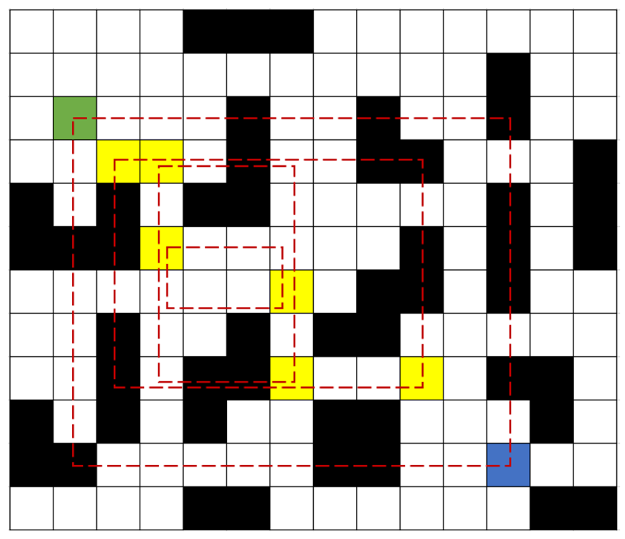
Figure 7 illustrates various elements of the pathfinding process: the green square indicates the start node; the blue square represents the goal node; the black squares refer to obstacles within the environment; and the yellow squares imply the minimum-cost nodes identified in forward and backward expansions. The red dashed rectangle is used to evaluate the current coverage rate of obstacles. Specifically, in the first expansion iteration of the bidirectional JPS algorithm, a rectangle search area is defined using the diagonal formed by the line connecting the start and goal nodes. This initial rectangle encompasses a total of 99 grid cells, of which 32 are designated as obstacle cells (represented by black squares). By applying Equation (5), the obstacle coverage rate is calculated as 32%. Based on the values presented in Table 1, this coverage rate corresponds to a circle expansion coefficient —determined as 1.2. Similarly, after the second expansion, the obstacle coverage rate increases to 35%, yielding = 1.2; after the third expansion, decreases to 25%, yielding = 1.15; and after the fourth expansion, no obstacles are found within the defined rectangle, leading to =1.

Figure 7.
Overview of the obstacle coverage rectangle.
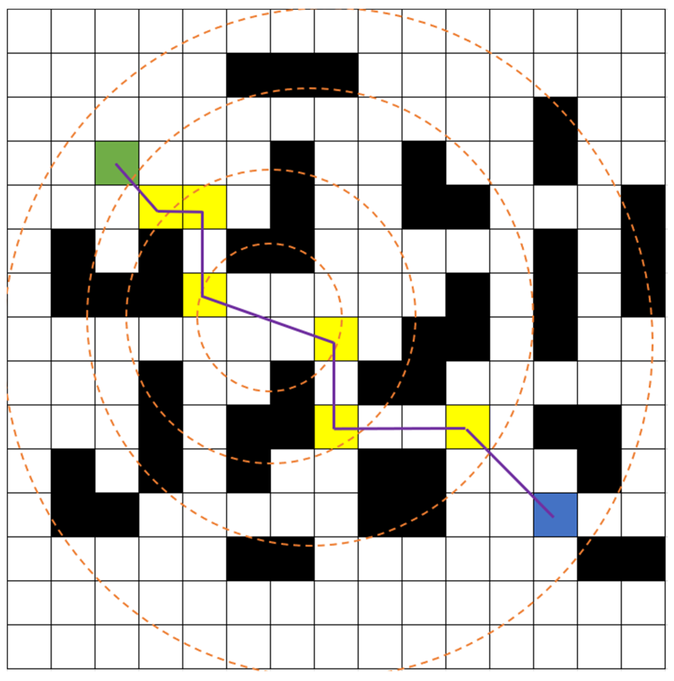
After determining the circle expansion coefficient is determined, a newly defined dynamic constraint circle is established. The circle is centered at the midpoint between the minimum-cost nodes identified in the forward and backward expansions. Its radius is calculated by taking into account half the product of as well as the distance separating these two nodes. As depicted in Figure 8, the purple lines indicate the traversed paths, while the remaining information remains the same as mentioned above. At the onset of the search process, the first dynamic constraint circle is generated. Its center is determined by the midpoint between the start and goal nodes, and its radius is calculated as half of the predefined scaling factor (initially set to 1.2) multiplied by the distance between the start and goal nodes. In subsequent iterations, the center of the constraint circle is redefined as the midpoint between newly identified minimum-cost nodes from both forward and backward expansions. Simultaneously, the radius is adjusted to reflect these updates, ensuring the formation of a new constraint circle. This process repeats until the pathfinding is completed.

Figure 8.
Overview of the dynamic constraint circle.
The dynamic constraint circle approach offers notable improvements over the conventional bidirectional JPS algorithm. By employing this method, the algorithm prioritizes expansions within the designated constraint circle when searching for jump points. This targeted expansion minimizes redundant node generation and reduces the number of intermediate expanded nodes and jump points. Since the boundary of the constraint circle is not considered an obstacle, it does not introduce additional jump points. This configuration ensures both the continuity and efficiency of the computed path. Furthermore, incorporating a dynamic constraint circle enhances the convergence between forward and backward searches, allowing the algorithm to quickly determine the optimal path. This benefit becomes particularly evident in complex environments, where it greatly improves the efficiency and accuracy of path planning.
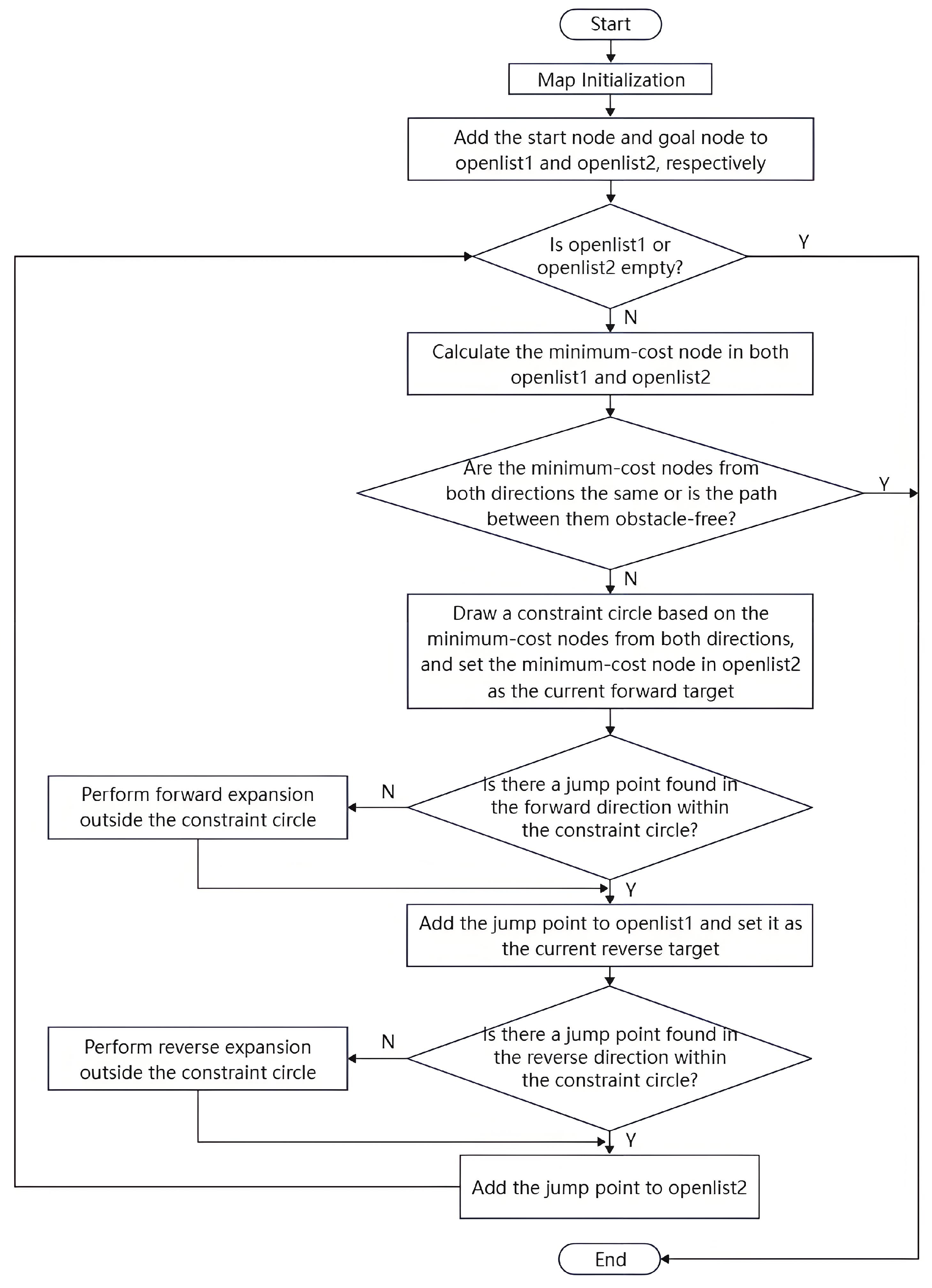
Considering the aforementioned improvements, this study presents the pseudo-code for the bidirectional JPS algorithm. The structured representation of the algorithm is provided in Algorithm 1. The overall trajectory planning logic and process are visualized in Figure 9. Improved algorithmic path planning flowchart. To facilitate bidirectional search, two open lists—openlist1 for the forward direction and openlist2 for the backward direction—are maintained separately throughout the algorithm.
| Algorithm 1: Bidirectional pathfinding improvement algorithm |
| 1: Input: Map Cost function 2: Output: Final optimal path: |
| 3: Initialization: 4: while or do 5: #calculate Minimum cost node 6: Forward: 7: Backward: 8: #Generated constraint circle 9: if or then |
10: return path S 11: else 12: Generate constraint circle with center = mid radius = r 13: #Forward Jump point search 14: if then 15: 16: else 17: Expand 18: #Backward Jump point search 19: if then 20: 21: else 22: Expand 23: end while 24: return S |
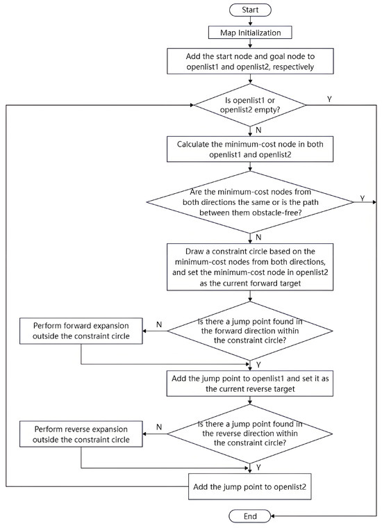
Figure 9.
Improved algorithmic path planning flowchart.
4. Simulation and Experimental Validation
4.1. Simulation Validation
All simulation experiments were carried out on a computer equipped with an Intel Core i5-10210U processor (base frequency 1.60 GHz, turbo frequency up to 4.20 GHz) and 12 GB RAM (Intel Corporation, Santa Clara, CA, USA), running Windows 10 (64-bit). MATLAB R2021b software, along with the Robotics System Toolbox, was used for algorithm implementation and performance evaluation. Grid maps with sizes of 20 × 20, 50 × 50, and 200 × 200 cells were generated with randomly distributed obstacles of varying densities to mimic realistic navigation scenarios. The starting and goal positions were strategically selected to represent typical robot path-planning tasks. Three primary metrics—path length (cumulative Euclidean distance), number of expanded nodes, and CPU search time—were recorded. To ensure statistical reliability and result stability, each scenario was independently simulated 10 times, with the averaged results presented in the manuscript.
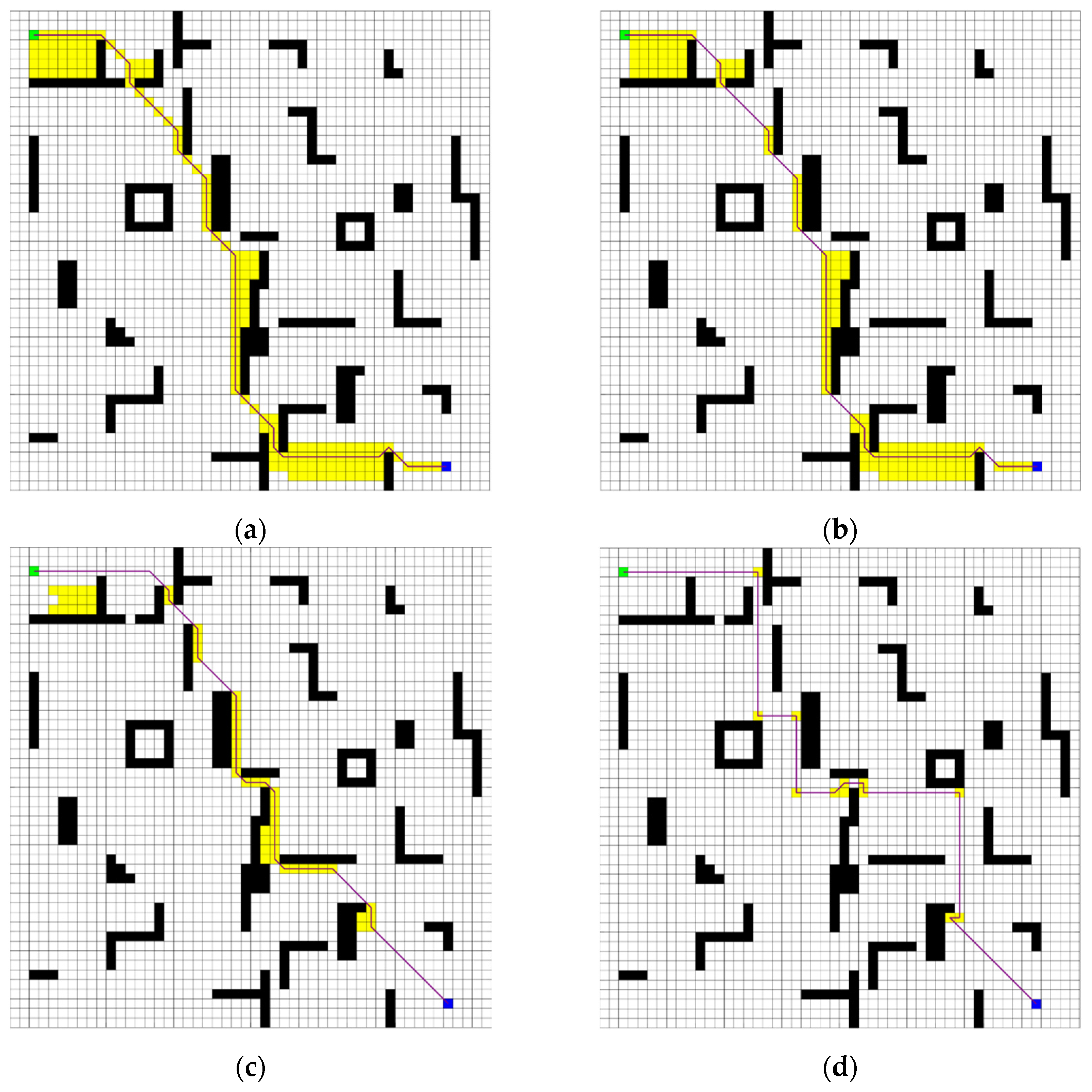
Figure 10 and Figure 11 illustrate the simulation outcomes for two grid maps, where green squares indicate the designated starting points; blue squares signify the goal nodes; black squares imply obstacles within the grid; yellow squares indicate the expanded jump points during searches; and purple lines represent the final planned paths. Table 2 and Table 3 present a comprehensive comparison of search times, path lengths, and the number of expanded nodes for the A* algorithm, the conventional JPS algorithm, the B-JPS algorithm, and the improved bidirectional JPS algorithm proposed in this study. These evaluations are conducted across the two different grid-map scenarios.

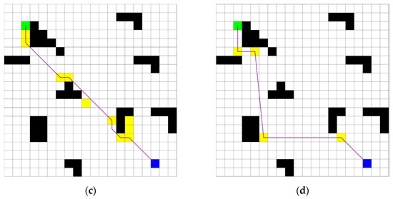
Figure 10.
Comparison plot in a 20 × 20 grid environment. (a) A* algorithm; (b) JPS algorithm; (c) B-JPS algorithm; (d) Improved algorithm.
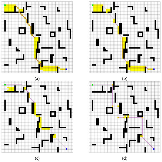
Figure 11.
Comparison plot in a 50 × 50 grid environment. (a) A* algorithm;(b) JPS algorithm; (c) B-JPS algorithm; (d) Improved algorithm.
Table 2.
Data comparison of four algorithms based on a 20 × 20 map environment.
Table 3.
Data comparison of four algorithms based on a 50 × 50 map environment.
As demonstrated in Figure 10 and Table 2, the A* algorithm exhibited a substantial number of node expansions within the 20 × 20 grid environment, leading to a prolonged search time. Compared with the A* algorithm, the traditional JPS algorithm reduced redundant node expansions through its jumping search strategy. This approach not only enhanced search efficiency but also contributed to a moderate reduction in overall search time. The B-JPS algorithm further decreased the number of node expansions by adopting a bidirectional search approach, initiating expansion from both the start and goal nodes. However, despite this reduction, it suffered from longer search times due to the additional preprocessing steps and increased computational complexity introduced by the dual-directional strategy. This computational overhead became particularly significant in smaller-scale environments with fewer nodes. A common drawback shared by these three algorithms is their failure to circumvent hazardous nodes while determining the optimal path—a crucial factor in mobile robot path planning.
The improved bidirectional JPS algorithm proposed in this study addresses these issues by significantly reducing unnecessary node expansions and effectively avoiding hazardous areas. By integrating an adaptive heuristic function and introducing a dynamic constraint circle into the alternating bidirectional search framework, the proposed algorithm demonstrates a substantial improvement in search efficiency and robustness. As shown in the 50 × 50 grid results, the algorithm maintains performance trends similar to those observed in the 20 × 20 environment, further validating its scalability and stability across varying map sizes and complexities.
To further demonstrate the broad applicability of the improved algorithm, a larger 200 × 200 grid map environment was constructed. Within this environment, four algorithms generated distinctly different paths, as depicted in Figure 12. In addition, Table 4 provides a comparative analysis of the search times for the A* algorithm, the conventional JPS algorithm, the B-JPS algorithm, and the proposed improved bidirectional JPS algorithm across different map environments, according to calculations based on Table 3.
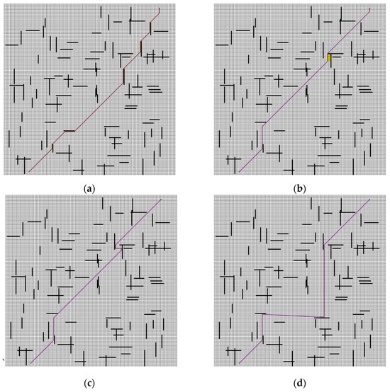
Figure 12.
Comparison plot in a 200 × 200 map environment. (a) A* algorithm; (b) JPS algorithm; (c) B-JPS algorithm; (d) Improved algorithm.
Table 4.
Comparison of search time of four algorithms across different map environments.
- For a 20 × 20 map, the enhanced bidirectional JPS algorithm demonstrated significant efficiency improvements, reducing the search time by 27.52%, 24.70%, and 60.89% compared with the A*, traditional JPS, and B-JPS algorithms, respectively.
- For the 50 × 50 map, the method demonstrated a significant reduction in search time, achieving improvements of 37.46%, 36.35%, and 66.27%.
- For the 200 × 200 map, the search time was reduced by 13.62%, 13.23%, and 12.55%.
These findings confirm that the proposed algorithm consistently delivers superior path planning performance across different levels of environmental complexity. It effectively avoids hazardous nodes, minimizes node expansions, and significantly accelerates the pathfinding process.
4.2. Experimental Validation
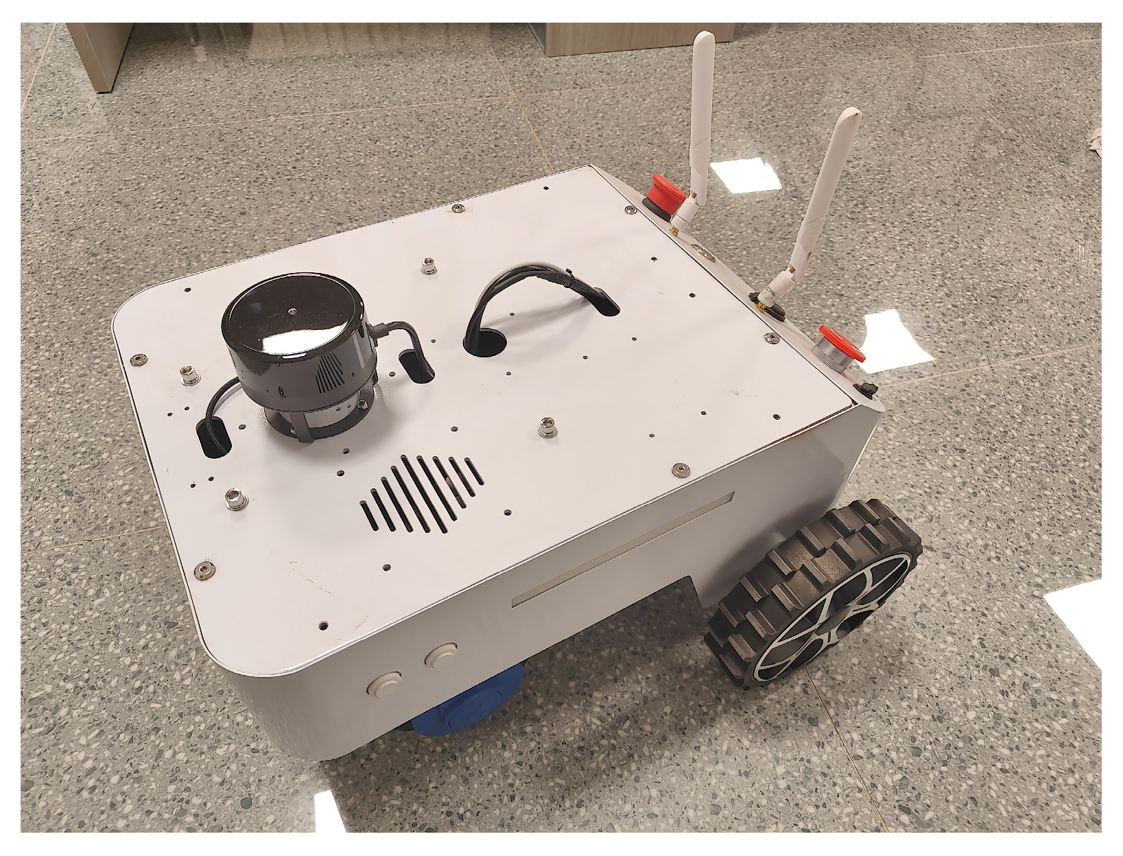
To further validate the effectiveness of the proposed improved bidirectional JPS algorithm in real-world applications, this study developed a platform based on a wheeled robot operating system. The robot employed in the experiment is a self-designed wheeled mobile robot (as shown in Figure 13) equipped with a 2D LiDAR sensor, a Pixhawk 2.4.8 flight controller integrated with an IMU (Inertial Measurement Unit), and an Intel NUC onboard computer as the primary computing device. The hardware architecture of the system is shown in Table 5. The platform possesses autonomous path-planning capabilities. Experiments were conducted under the Ubuntu 20.04 LTS operating system with ROS Noetic Ninjemys installed, integrating several key ROS packages, including the navigation stack, move_base, AMCL (Adaptive Monte Carlo Localization), Gmapping (Simultaneous Localization and Mapping—SLAM), and the visualization tool Rviz.
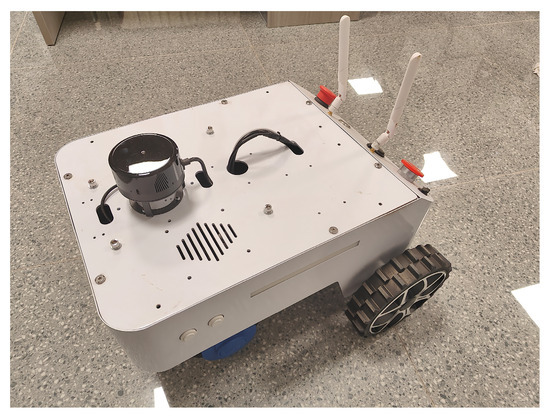
Figure 13.
ROS mobile robot.
Table 5.
Hardware Architecture of the Wheeled Mobile Robot.
The ROS-based system architecture consists of the following three primary modules:
- The 2D LiDAR sensor is used for global map construction and obstacle detection. This module employs the ROS-SLAM-Gmapping algorithm, a classic 2D SLAM method that combines particle filtering with LiDAR-based environment mapping. Gmapping allows for simultaneous map building and real-time pose estimation of the robot within the environment while generating accurate obstacle maps. Additionally, noise suppression and smoothing techniques are applied to the LiDAR data to significantly enhance mapping precision.
- The localization module combines IMU-based odometry, 2D LiDAR data, and the AMCL algorithm. AMCL is a probabilistic localization method based on particle filtering. By randomly sampling particles, AMCL captures the uncertainty in the robot’s pose estimation and dynamically adjusts particle weights based on sensor observations, thereby forming a reliable posterior probability distribution and enabling accurate real-time localization.
- Path Planning and Motion Control Module: The onboard Intel NUC is responsible for integrating the improved bidirectional JPS algorithm into the system’s navigation framework. Communication between hardware components is achieved through ROS nodes using the MAVLink protocol. The architecture of the navigation framework is shown in Figure 14.
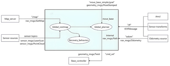 Figure 14. Framework diagram of navigation.
In this navigation framework, the map_server node is responsible for loading and publishing the global static map generated by the 2D LiDAR scans. The odometry source module integrates wheel encoder data with IMU measurements to provide robot robots with real-time pose tracking and motion state feedback. The sensor sources module perceives environmental obstacles and updates the costmap accordingly. Additionally, the recovery_ behaviors module is designed to handle navigation anomalies or failures. All these modules communicate through ROS topics and services, forming a loosely coupled collaborative system that ensures robust navigation performance.
The execution procedure for the high-level algorithm is described as follows: First, the target pose is published via the move_base_simple/goal topic. The move_base controller then invokes the improved bidirectional JPS algorithm within the global_planner module, directly accessing data from the global static map. Subsequently, the bidirectional jump point search strategy computes the globally optimal path, and the resulting path point sequence is published as a nav_msgs/Path message type. Finally, the global path is transformed into velocity commands, which are sent through the/cmd_vel topic to the wheeled robot’s motion controller to execute real-time movements. Throughout this process, the costmap_2d module continues maintaining the costmap, serving exclusively for global replanning decisions.
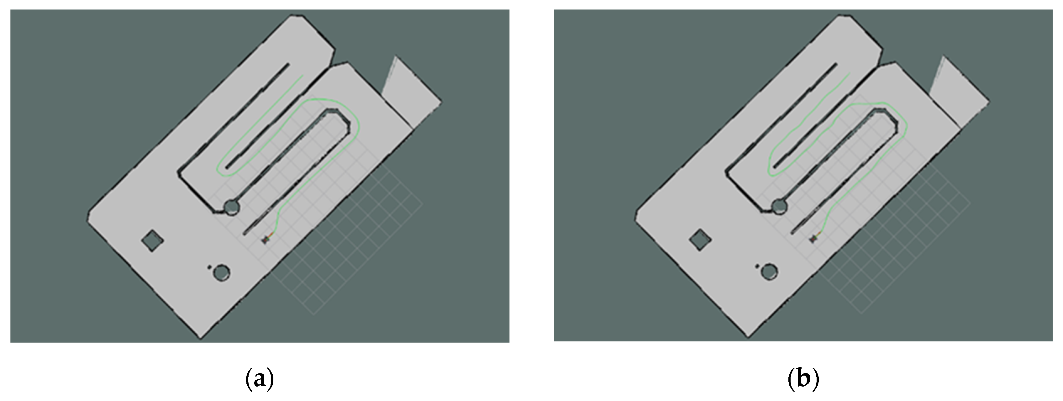
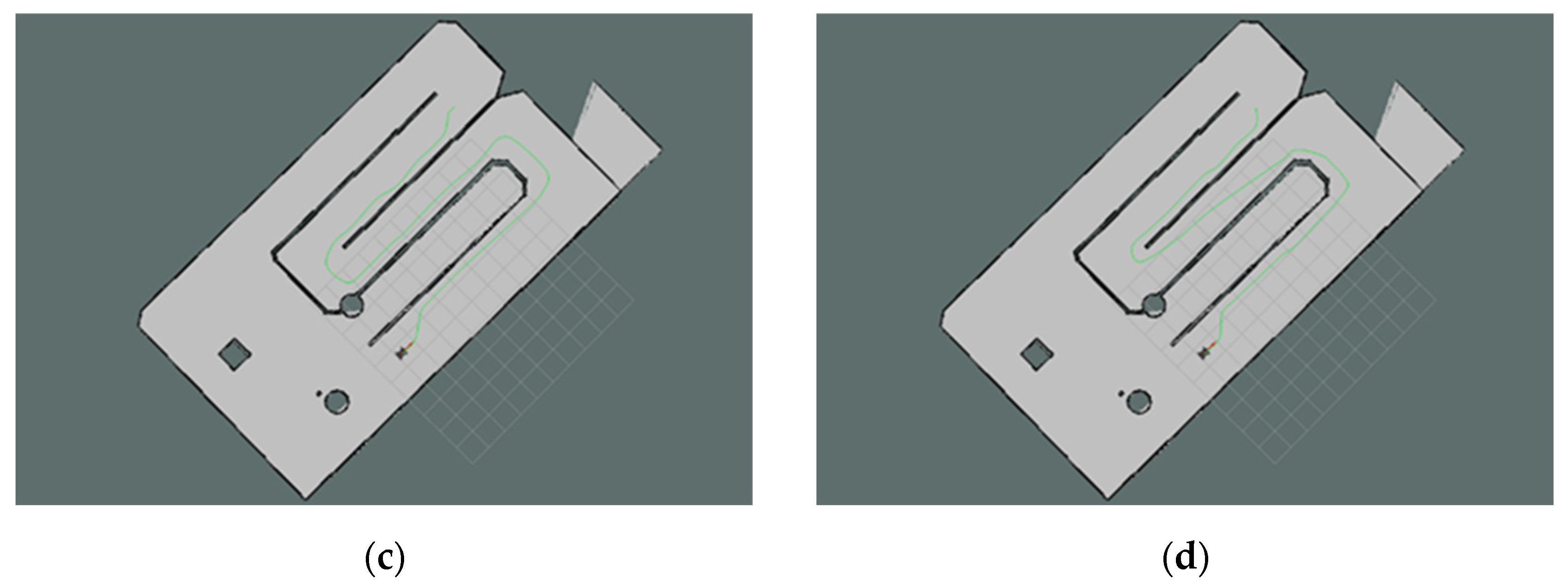
The path planning executed by the ROS robot in the experimental site is illustrated in Figure 15. The results of the path planning were revisualized using the ROS visualization tool—Rviz. The solid green line in the figure depicts the path planned by the improved bidirectional JPS algorithm.
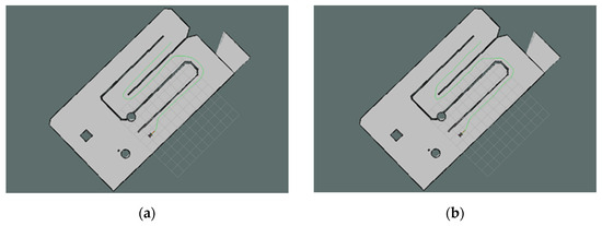
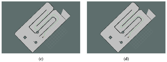
Figure 15.
Path planning configuration of the mobile robot in the experimental site. (a) A* algorithm; (b) JPS algorithm. (c) B-JPS algorithm; (d) Improved algorithm.
Table 6 provides a comparative analysis of path length and search time for the four algorithms applied to the same map in the physical experiments. The experimental results demonstrate that the proposed algorithm substantially decreases search time while simultaneously producing near-optimal paths. The observed reduction in search time can be primarily attributed to the dynamic constraint circle, which effectively limits the search space during each iteration. This constraint guides the bidirectional expansion process, prioritizing nodes that lie within the most promising region between the two search fronts. Additionally, the adaptive heuristic function accelerates convergence by adjusting the weight dynamically based on the robot’s proximity to the goal, thereby improving the algorithm’s overall responsiveness.
Table 6.
Comparison of experimental results of the four algorithms in a real-world environment.
While the path length remains near-optimal, minor deviations were observed in the real-world implementation compared to the simulated results. These deviations are mainly due to sensor noise, imperfect localization accuracy, and the non-holonomic motion constraints of the physical robot. Unlike in simulation, where the robot can follow waypoints with perfect accuracy, in real-world environments, the robot’s mechanical limits and actuation delay introduce slight discrepancies in the actual path followed. Despite these small variations, the proposed algorithm consistently outperformed the traditional A*, standard JPS, and B-JPS methods in both planning efficiency and execution quality. This clear advantage underscores its practical value in mobile robot path planning applications.
5. Conclusions
In this study, an improved bidirectional dynamic Jump Point Search (JPS) algorithm was proposed to address problems commonly found in traditional path planning methods, including excessive node expansion, inefficient search, and poor path safety. The algorithm introduces two main improvements: an adaptive heuristic weighting coefficient, which dynamically adjusts the evaluation of the heuristic function, and a dynamic constraint circle, which limits the expansion area and improves search efficiency. Simulation results on different grid map sizes show that the proposed method significantly reduces search time, decreases the number of expanded nodes, and avoids hazardous areas while maintaining near-optimal path quality. The effectiveness of the algorithm was further validated through real-world experiments using a ROS-based mobile robot platform.
Looking forward, future research will focus on integrating the improved bidirectional JPS algorithm with the Dynamic Window Approach (DWA) to enhance local obstacle avoidance capabilities. This hybrid approach is expected to combine the global efficiency of JPS with the real-time responsiveness of DWA. Furthermore, efforts will be made to extend the proposed method to fully dynamic or partially unknown environments, enabling more adaptive and robust navigation in complex, real-world scenarios.
Author Contributions
Conceptualization, R.G. and C.B.; methodology, R.G.; software, R.G.; validation, R.G. and X.Q.; formal analysis, R.G. and; investigation, R.G. and X.Q.; resources, R.G.; data curation, R.G.; writing—original draft preparation, R.G.; writing—review and editing, R.G. and C.B.; supervision, C.B.; project administration, C.B.; funding acquisition, C.B. All authors have read and agreed to the published version of the manuscript.
Funding
The APC was funded by the Inner Mongolia Key Laboratory of New Energy and Energy Storage Technology.
Data Availability Statement
Data are contained within the article.
Conflicts of Interest
The authors declare no conflicts of interest.
References
- Huang, Y.; Chen, D. Research Progress of Automatic Driving Path Planning. In Proceedings of the 2021 2nd International Conference on Artificial Intelligence and Computer Engineering (ICAICE), Hangzhou, China, 5–7 November 2021; pp. 95–99. [Google Scholar] [CrossRef]
- Sánchez-Ibáñez, J.R.; Pérez-Del-Pulgar, C.J.; García-Cerezo, A. Path planning for autonomous mobile robots: A review. Sensors 2021, 21, 7898. [Google Scholar] [CrossRef] [PubMed]
- Raja, P.; Pugazhenthi, S. Optimal path planning of mobile robots: A review. Int. J. Phys. Sci. 2012, 7, 1314–1320. [Google Scholar] [CrossRef]
- Yu, H.; Meng, Q.; Fang, Z.; Liu, J.; Xu, L. A review of ship collision risk assessment, hotspot detection and path planning for maritime traffic control in restricted waters. J. Navig. 2022, 75, 1337–1363. [Google Scholar] [CrossRef]
- Tsardoulias, E.G.; Iliakopoulou, A.; Kargakos, A.; Petrou, L. A review of global path planning methods for occupancy grid maps regardless of obstacle density. J. Intell. Rob. Syst. 2016, 84, 829–858. [Google Scholar] [CrossRef]
- Tee, Y.K.; Han, Y.C. Lidar-Based 2D SLAM for Mobile Robot in an Indoor Environment: A Review. In Proceedings of the 2021 International Conference on Green Energy, Computing and Sustainable Technology (GECOST), Miri, Malaysia, 7 July 2021; pp. 1–7. [Google Scholar] [CrossRef]
- Abujabal, N.; Fareh, R.; Sinan, S.; Baziyad, M.; Bettayeb, M. A comprehensive review of the latest path planning developments for multi-robot formation systems. Robotica 2023, 41, 2079–2104. [Google Scholar] [CrossRef]
- Xu, Y.; Guan, G.; Song, Q.; Jiang, C.; Wang, L. Heuristic and random search algorithm in optimization of route planning for Robot’s geomagnetic navigation. Comput. Commun. 2020, 154, 12–17. [Google Scholar] [CrossRef]
- Osmankovic, D.; Tahirovic, A.; Magnani, G. All Terrain Vehicle Path Planning based on D* lite and MPC based Planning Paradigm in Discrete Space. In Proceedings of the 2017 IEEE International Conference on Advanced Intelligent Mechatronics (AIM), Munich, Germany, 3–7 July 2017; pp. 334–339. [Google Scholar] [CrossRef]
- Mandloi, D.; Arya, R.; Verma, A.K. Unmanned aerial vehicle path planning based on A* algorithm and its variants in 3d environment. Int. J. Syst. Assur. Eng. Manag. 2021, 12, 990–1000. [Google Scholar] [CrossRef]
- Pu, X.; Xiong, C.; Ji, L.; Zhao, L. 3D path planning for a robot based on improved ant colony algorithm. Evol. Intell. 2024, 17, 55–65. [Google Scholar] [CrossRef]
- Huang, H.-C.; Tsai, C.-C. Global Path Planning for Autonomous Robot Navigation using Hybrid Metaheuristic GA-PSO Algorithm. In Proceedings of the SICE Annual Conference 2011, Tokyo, Japan, 13–18 September 2011; pp. 1338–1343. [Google Scholar]
- Hong, J.; Tsai, R.-G.; Chen, X.; Lin, D.; Yu, Y.; Lin, Y.; Li, R. U*: GA-based path planning algorithm for surface floating garbage cleaning robot. J. Intell. Fuzzy Syst. 2024, 46, 837–850. [Google Scholar] [CrossRef]
- Xu, R.; Tian, J.; Li, J.; Zhai, X. Trajectory planning of rail inspection robot based on an improved penalty function simulated annealing particle swarm algorithm. Int. J. Control Autom. Syst. 2023, 21, 3368–3381. [Google Scholar] [CrossRef]
- Yang, D.; Dong, L.; Dai, J.K. Collision avoidance trajectory planning for a dual-robot system: Using a modified APF method. Robotica 2024, 42, 846–863. [Google Scholar] [CrossRef]
- Noreen, I.; Khan, A.; Habib, Z. Optimal path planning using RRT* based approaches: A survey and future directions. Int. J. Adv. Comput. Sci. Appl. 2016, 7, 97–107. [Google Scholar] [CrossRef]
- Harabor, D.; Grastien, A. Online Graph Pruning for Pathfinding On Grid Maps. In Proceedings of the AAAI Conference on Artificial Intelligence, San Francisco, CA, USA, 7–11 August 2011; pp. 1114–1119. [Google Scholar] [CrossRef]
- Ren, X.; Wang, Z.; Tang, J. Mobile Robot Path Planning Based on Improved A* Algorithm Fused with JPS. In Proceedings of the Proceedings of the 2024 3rd International Symposium on Control Engineering and Robotics, Changsha, China, 24–26 May 2024. [CrossRef]
- Wang, F.; Sun, W.; Yan, P.; Wei, H.; Lu, H. Research on path planning for robots with improved A* algorithm under bidirectional JPS strategy. Appl. Sci. 2024, 14, 5622. [Google Scholar] [CrossRef]
- Lin, Z. Path safety inflation planning algorithm based on improved JPS. Front. Soc. Sci. Technol. 2024, 6, 48–53. [Google Scholar] [CrossRef]
- Zheng, X.; Tu, X.; Yang, Q. Improved JPS Algorithm Using New Jump Point for Path Planning of Mobile Robot. In Proceedings of the 2019 IEEE International Conference on Mechatronics and Automation (ICMA), Tianjin, China, 4–7August 2019; pp. 2463–2468. [Google Scholar] [CrossRef]
- Wang, Z.; Tu, H.; Chan, S.; Huang, C.; Zhao, Y. Vision-based initial localization of AGV and path planning with PO-JPS algorithm. Egypt. Inf. J. 2024, 27, 100527. [Google Scholar] [CrossRef]
- Ren, J.; Zhang, Y. Planning of JPS Algorithm Based on Direction Region Priority Improvement. In Proceedings of the Third International Conference on Intelligent Mechanical and Human-Computer Interaction Technology (IHCIT 2024), Hangzhou, China, 5–7 July 2024; p. 47. [Google Scholar] [CrossRef]


Disclaimer/Publisher’s Note: The statements, opinions and data contained in all publications are solely those of the individual author(s) and contributor(s) and not of MDPI and/or the editor(s). MDPI and/or the editor(s) disclaim responsibility for any injury to people or property resulting from any ideas, methods, instructions or products referred to in the content. |
© 2025 by the authors. Licensee MDPI, Basel, Switzerland. This article is an open access article distributed under the terms and conditions of the Creative Commons Attribution (CC BY) license (https://creativecommons.org/licenses/by/4.0/).