Article

Frequency-Selective Surface Based 360-Degree Beam-Steerable Cavity Antenna for UAV Swarm Coordination

Missouri Institute for Defense & Energy (MIDE), University of Missouri-Kansas City, Kansas City, MO 64110, USA
*
Author to whom correspondence should be addressed.
Electronics 2025, 14(9), 1725; https://doi.org/10.3390/electronics14091725
Submission received: 30 March 2025 / Revised: 19 April 2025 / Accepted: 21 April 2025 / Published: 24 April 2025
(This article belongs to the Special Issue Control Systems for Autonomous Vehicles)

Abstract

:
A swarm of unmanned aerial vehicles (UAVs) often rely on exceptional wireless coverage of embedded or flush-mounted antennas or arrays, especially in long-range communication. While arrays offer significant range and beam steerability control, they often suffer from size, weight, and power (SWaP) limitations. On the other hand, achieving a wideband, high-gain, and beam-steerable response from a single antenna is highly desired for its compact SWaP characteristics. In this study, a cube-shaped cavity antenna excited by a monopole feed is designed, fabricated, and measured. The proposed antenna operates from 4.1 to 5.56 GHz with a 30.22% fractional bandwidth and a peak gain of 8 dBi. In addition, a frequency-selective surface (FSS) is developed to replace the metallic faces of the cavity, enabling 360° electronic beam steerability. Thermal analysis of the FSS-based cavity design is conducted to determine its maximum power handling capability, revealing a maximum power handling capability of 1.3 KW continuous. In addition, the maximum rating currents of the FSS diodes can be reached only at 165 W, limiting the maximum power handling to only 165 W in the case of using the diodes used in this analysis. The antenna prototype is successfully fabricated, and the radiation pattern is experimentally measured, showing a strong agreement between the simulated and measured results. The electronic steerability of the proposed antenna indicates its suitability for 5G new radio and UAV applications.

1. Introduction

The need for advanced antenna systems is crucial in the fast-paced world of wireless communications and 5G wireless networks. These systems might encompass wideband antennas, high-gain antennas, steerable antennas, or a blend of these features tailored to the particular demands of the communication context [1,2]. However, designing a low-profile antenna that achieves high gain, wide bandwidth, and steerability remains an ongoing challenge [3,4,5,6,7,8,9]. In addition, due to their operation in high frequencies, 5G communications are vulnerable to environmental factors. Therefore, the wireless communication industry has been investigating high-directivity antennas with beam-steering capabilities to accurately direct the signal to the receiver and counteract the high signal loss [1,2]. Moreover, beam-steerable antennas are widely used in many other civilian and military applications, including unmanned aerial vehicles (UAVs) [10]. Beam-steerable antennas play a vital role in UAV swarm coordination by providing adaptable, high-gain communication links between drones and control stations—without the need to physically move the UAV. Maintaining reliable and interference-free connections demands the quick adjustment of signal direction since drones in a swarm are constantly shifting their positions [11,12]. Beam-steerable antennas allow each UAV to focus its transmission toward intended targets, improving signal quality, conserving energy, and reducing interference with nearby units. This capability becomes especially important in tightly packed swarms or cluttered environments, where omnidirectional antennas may struggle due to signal fading and reflections. Chen et al. [13] used an omnidirectional antenna in their research, which offers low directivity, resulting in reduced coverage or increased energy loss. By leveraging electronic beam steering, UAV swarms can achieve more robust, efficient, and synchronized operations, which are crucial for formation control, real-time communication, and joint task execution. Recent research efforts are also exploring the use of dynamic metasurface antennas for beam-steering applications.
Dynamic metasurface antennas offer a highly efficient and scalable solution for beam steering in next-generation wireless communication systems [14]. Unlike conventional antenna arrays that rely on bulky and power-hungry phase shifters, DMAs leverage tunable metamaterial elements integrated into compact surfaces to dynamically shape and direct electromagnetic beams. This capability enables real-time beam tailoring and holographic beamforming, allowing the antenna to precisely steer signals toward intended users while minimizing interference and energy waste. By processing signals in the analog domain and reducing the number of required RF chains, DMAs not only lower power consumption and hardware complexity but also support massive MIMO configurations in space-constrained environments. These unique features make DMAs an ideal candidate for implementing agile and cost-effective beam steering in dense urban and indoor deployments envisioned for 6G networks.
Several techniques are available for steering an antenna’s beam. The most common are electronic, mechanical, optical methods, and smart antenna materials [15,16]. Electronically, beam steering can be achieved using a phased array or an active transmitarray surface [15,16]. In phased arrays, phase shifters are used, while in active transmitarray surfaces, diodes and varactors are typically employed. Mechanically, beam steering is accomplished by changing the antenna’s orientation through motors or other mechanisms [15,16]. Typically, mechanical beam steering can be achieved over wideband [17,18]; however, it is not applicable to UAV applications due to its complexity and weight. Optical beam steering utilizes optical photoconductive switches, and smart antenna materials steer the beam by electrically modifying substrate parameters [1].
Achieving wide-angle beam steerability is often possible with phased array antennas.
Phased array antennas operate by controlling the phase of the transmitted radiation when operated as a stepped frequency system or, equivalently, by altering the relative timing of the signals received/transmitted in the time domain. Hence, it needs a complex feeding network and typically does not meet UAVs’ small-size requirements [19,20]. Several researchers have suggested electronic steerable antenna arrays to overcome the SWaP criteria for small UAVs using spatially distributed antenna elements carried on UAVs [12,21]. However, this technique requires a group of UAVs to achieve the desired steerability. On the other hand, in most other electronically controlled beam-steerable designs, wideband antennas experience limitations in scanning angle [22,23]. For instance, Stroh, Antonio et al. [2] and Zhang, Lin-Man et al. [24] achieved 360-degree beam steerability using pin diodes and varactors but with only a ~3% and ~5% bandwidth, respectively.
In this work, we designed a cube-shaped cavity antenna based on FSS to achieve 360-degree beam steering across the full azimuth plane. An N-type-to-waveguide transition with a thick monopole was employed to excite the cavity. Pin diodes were used as RF switches to control the FSS electronically. Any face of the cavity antenna can be activated by adjusting the biasing voltage of the pin diodes leading to steering the beam in the desired direction. Additionally, thermal analysis was conducted to study temperature distribution and the impact of high power on the antenna’s performance. While we currently do not intend to extend the design into an antenna array, the number of monopole antennas can be increased significantly, hence forming an array-like design. Unlike arrays, this design aims to achieve high performance and beam steerability without the need for phase shifters, which are expensive, bulky, and complex designs. In addition, the number of FSS layers can be increased on each face, forming a lensing effect and further improving the proposed antenna’s performance and hence illuminating the need for arrays.
The novelty of this design lies in its low profile, with the largest dimension being only 0.5λ and simple feed design while still enabling 360-degree beam steerability. The antenna has a 30% bandwidth and offers a peak gain of 8 dBi. Moreover, to the best of our knowledge, this is the first time thermal analysis has been performed to find the thermal mapping of an FSS antenna when subjected to high power. Preliminary versions of this work were presented in [8,25]. However, the preliminary versions were narrow-band designs.
It is worth mentioning that Zhang, Wu et al. suggested that antenna performance can be adversely affected when exposed to shaking and jittering caused by motion [26]. The proposed antenna will be mounted onto the UAV frame using a rigid, vibration-absorbing fixture, effectively minimizing any mechanical displacement resulting from such motion. This stable mounting ensures the antenna’s orientation remains aligned with the desired communication direction.
Additionally, the antenna’s integrated beam-steering capability enhances resilience by enabling real-time electronic adjustment to counteract minor misalignments. These combined strategies ensure reliable and consistent communication performance, even under dynamic flight conditions. Moreover, UAV antennas can be strategically integrated into various structural components—such as the landing gear, fuselage, or even directly mounted in the UAV arm, as highlighted by Muzalevskiy et al. [27], allowing flexible deployment options without compromising aerodynamic efficiency.

2. Antenna Design

The primary principle of beam steering using a cavity-backed antenna is illustrated in Figure 1. The antenna consists of a cube-shaped cavity with six faces and a monopole antenna as the radiator. Since the monopole has an omnidirectional radiation pattern, the electromagnetic field will radiate in that specific direction when any face of the cube cavity is opened. For example, if the right face of the cavity is opened while keeping all other faces closed, the electromagnetic field will radiate through the right face. Similarly, if the left face is opened and all other faces are closed, the field will radiate exclusively through the left face.

2.1. Cavity Design

The design process for the proposed antenna involves two primary steps: designing the cube-shaped cavity and designing the FSS unit cell. Figure 2 shows the cube-shaped cavity antenna without the FSS, highlighting the fundamental structure before integrating the FSS unit cells for enhanced steerability. The antenna cavity measures 60 × 60 × 60 mm3. The cavity is made of Perfect Electric Conductors (PECs). PECs were used since copper is considered a PEC at a low frequency. In addition, the simulation time is much faster when assigning a PEC as the metal instead of lossy materials. Hence, due to the complexity of the simulation domain with many diodes involved, the PEC was assigned to metallic parts. We used CST Studio Suite for the simulation and performed the analysis using the time-domain solver [28]. The mesh was set using the standard global mesh settings. Open boundary conditions were applied to model the antenna in a free-space environment.
This antenna operates in a frequency range from 2.9 GHz to 5.43 GHz and achieves a peak gain of 9 dBi, as illustrated in Figure 2b,c. Figure 2d demonstrates that by opening only one face of the cavity at a time, the beam can be steered in a specific plane. A monopole is used to feed the cavity, and the cavity design converts the omnidirectional radiation of the monopole into directional radiation. However, this design requires continuously changing the open face of the cavity to allow for beam steerability. Therefore, we introduced the FSS to replace the PEC.

2.2. FSS Design

It is impractical to open one face at a time mechanically, so electronically opening the faces is a more feasible solution. FSS unit cells, integrated with pin diodes, enable the beam to steer electronically depending on the state of the FSS. The FSS is constructed on a 0.5 mm thick Rogers RT-duroid 5880 substrate (Rogers Corporation, Chandler, AZ, USA), chosen for its low permittivity, which minimizes loss and enhances the antenna’s performance across a wide frequency range. In Figure 3a, green represents the diode, yellow indicates the metal, and white shows the substrate. We use the SMP1340-079LF pin diode (Skyworks Solutions, Inc., Irvine, CA, USA) to alter the state of the unit cell, modeling the diode as RLC lumped elements to simulate its different states, as depicted in Figure 3b. Figure 3b illustrates the equivalent circuit of the diode during forward bias and reverse bias, which corresponds to the on state and off state of the diode [29]. In CST, for each unit cell, a perfect magnetic boundary condition (PMC) is set along the x-axis and a perfect electric boundary condition (PEC) along the y-axis. A standard mesh size was utilized, and the simulation was carried out in the time domain using the CST full-wave simulator.
Figure 4 illustrates that when the diode is in the off state, the FSS allows the transmission of the waves, acting as an open face. Contrarily, the FSS blocks radiation when the diode is on, acting as a closed face. Hence, the diode can be used to electronically control each face to open and close by turning on and off the diode. Therefore, the proposed FSS is used to replace the cavity walls. Figure 5a presents the cube-shaped cavity integrated with the FSS.

3. Discussion

3.1. Complete FSS-Based Cavity Antenna Design

S11, indicating the return loss of the complete design shown in Figure 5a, is shown in Figure 5b. Figure 5c illustrates the 360° radiation pattern achieved by selectively opening each face of the cube one at a time through the biasing of the pin diodes. This capability allows for precise control over the direction of the radiation by selectively biasing the diodes of each face.
To ensure that our antenna operates effectively within the frequency bands commonly used for unmanned aerial vehicles (UAVs), we made specific adjustments to the original design shown in Figure 5d. In particular, we (i) increased the overall structure size by 70% and (ii) reduced the antenna model’s physical dimensions by 10%. These design changes were carefully chosen to shift the antenna’s frequency response to center around 2.4 GHz and 5.8 GHz—two widely adopted frequency bands in UAV communications due to their favorable propagation characteristics and compatibility with existing UAV systems. By aligning the antenna’s resonant frequencies with these target bands, we improved its applicability for UAV-based wireless communication scenarios. This modification not only enhances the antenna’s performance in practical UAV applications but also demonstrates its scalability in adapting to real-world deployment requirements.
Furthermore, the antenna system fidelity factor (SFF) was evaluated to verify the robustness of the proposed design’s signal integrity at different distances. The fidelity factor (FF) of an antenna depicts the antenna’s capability to transmit and receive signals without distorting the temporal profile of the signal [30]. The fidelity factor of an antenna can be mathematically represented as the cross-correlation between the transmitted and the received signal in the time domain as follows [30]:
F F = m a x t T s ( t ) R s ( t + τ ) d t [ | T s ( t ) | 2 d t ] 1 / 2 [ | R s ( t ) | 2 d t ] 1 / 2
where T s ( t ) is the transmitted signal, R s t is the received signal, and τ is the time delay between the two signals. A fidelity factor (FF) of 1 indicates that the received signal retains the exact shape and characteristics of the transmitted signal, signifying excellent signal integrity. On the other hand, if the FF is less than 0.5, it indicates significant distortion in the received signal, suggesting a substantial deviation from the original transmitted signal.
The system fidelity factor (SFF), which calculates the distortion produced by an antenna when transmitting at different distances [31], was also evaluated for the prototype. To estimate the angular SFF, the receiving antenna was rotated around the axis of the transmitting antenna in 10° increments at distances of 500 mm and 1000 mm. The reference angle is when the antennas are in a face-to-face configuration. The SFF for 500 mm and 1000 mm distances is shown in Figure 6a,b, which indicates the proposed antenna’s ability to radiate at all angles for different distances without distorting the radiated signal. That is, the minimum achievable SFF is 0.8199, while the maximum value is 0.9521.
It is worth mentioning that, according to the latest research on intentional and unintentional electromagnetic interference in power electronics, UAV antennas can represent a direct link for unwanted interference [32,33]. That is, there are two different ways of interference to UAVs: (i) front-door coupling, coupling through the antennas; and (ii) back-door coupling, through wires, seams, and all unintentional antennas [32,33]. Although back-door coupling represents a potential threat to the performance of the UAV [32,33], this is out of the scope of this work. In our previous publications, we extensively studied back-door coupling for quadcopters and the potential ways to mitigate it [34]. In addition, the conclusions presented in [34] were validated through extensive experimental measurements by Li, Jilu et al. [35].
For front-door coupling, the proposed antenna offers a unique feature that is not available in most, if not all, conventional antennas. This feature closes all faces of the cavity, leading to the blockage of front-door coupling. Figure 7 shows the SParameters of the cavity when all the faces are closed; all diodes are forward-biased. Figure 7 illustrates that the proposed antenna can block unintentional interference within the antenna’s operation band. The previously mentioned feature illustrates the applicability of the proposed design in UAVs and other highly congested communication applications.

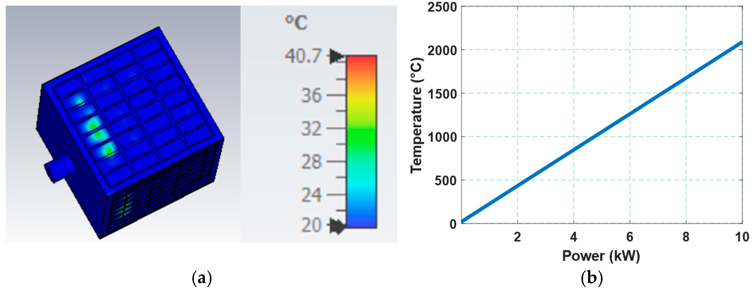
3.2. Antenna Power Handling Capability

The thermal breakdown of the design can be (i) reaching the air breakdown, which leads to sparking, studied in our previous work, and shows that the design can withstand >1 MW without sparking [8]; (ii) reaching the melting point of the substrate, studied through thermal analysis; and (iii) reaching the maximum rated current of the diodes, studied through measuring the current across the diodes for each input power.

3.2.1. Thermal Effect

Thermal analysis is primarily conducted to assess the impact of temperature on a specific surface as that temperature increases. For UAV applications, it is often necessary to increase the input power, which subsequently increases the current throughout the surface, resulting in a temperature rise. If this temperature exceeds the breakdown temperature of the materials constituting the antenna, it could adversely affect the performance and efficiency of the antenna. Furthermore, high temperatures can lead to the potential melting of the antenna.
The thermal solver of CST [28] was utilized to evaluate the thermal mapping of the designed cavity antenna when subjected to high power. In the thermal solver, the input power can be incrementally increased, and the resultant thermal mapping on the surface of the antenna can be observed. The thermal mapping provides insight into the maximum power the antenna can endure when subjected to high input power.
This study considers input power levels of 1 W to 10,000 W. Thermal mapping was observed at each input power level. Figure 8a presents an example of the cavity antenna’s thermal mapping. Figure 8a displays the thermal mapping for 100 W input power when the antenna is excited at a center frequency of 4.9 GHz. At 100 W, the cavity’s maximum temperature reaches 40.7 °C. Figure 8b illustrates the maximum temperature reached at the surface of the antenna for different input power levels. Figure 8b reveals the linear trend of the temperature increase across the surface of the antenna for different input powers.
The cavity antenna consisted of Rogers RO 4350B substrate and copper; the melting temperatures were 280 °C and 1084 °C, respectively. Therefore, we defined the thermal breakdown of the design as 280 °C, the lowest temperature among the previously mentioned materials. After testing different input power levels, we found that the surface temperature reached ~280 °C after applying ~1.3 KW input power. Therefore, the maximum power handling capability of the cavity to withstand the melting temperature was ~1.3 KW. It is worth mentioning that this power limit is for continuous input excitation. Hence, the antenna might handle more power for short-pulse excitation. In addition, the maximum temperature reached for each input power is very localized and will not reach the melting point of the Rogers. We did not analyze the exact input power value further to damage the substrate since we expect that the maximum current crossing the diodes will be reached for lower input powers.

3.2.2. Component Effect

As mentioned in the previous section, the SMP1340-079LF pin diode introduced beam steerability. The maximum current that the pin diode could endure was 0.1 A [36]. The CST time domain solver was used to estimate the current moving through the pin diodes on the surface of the FSS. We performed an extensive analysis of different input power levels. Figure 9 shows the current across the diode for 165 W. Clearly, the pin diode reached 0.1 A (the maximum rated current). Hence, the power handling capability of the proposed design significantly dropped to 165 W.

4. Results

The antenna prototype was fabricated to validate its performance experimentally. Figure 10 illustrates the front and back views of the fabricated FSS. The back side prominently contains the feeding network, with the circuit traces connected to the metasurface on the top side through vias. The diodes were biased using a DC power supply, with the positive and negative terminals of the diodes connected to a breadboard via jumper wires. The FCC was then used to construct the cavity. The face with the monopole was constructed with copper tape on top of a 3D printed sheet. The scattered parameters of the prototype under different biasing conditions are shown in Figure 11. The differences between the faces’ scattering parameters are due to the fabrication tolerance for each face. In addition, the huge number of diodes adds uncertainty regarding the functionality of each one. However, we generally achieved good agreement between measurement and simulations.
Figure 12 shows the experimental setup used to assess the radiation pattern of the fabricated antenna. A horn antenna with a known S11 parameter and gain was employed as the reference antenna. Radiation pattern measurements were conducted in a semi-anechoic chamber, where the antenna under test was mounted on a turntable. The turntable system consisted of a stepper motor for precise rotation and a Wi-Fi module for wireless communication between a Raspberry Pi controller and the main computer. The turntable was incrementally rotated from 0° to 360° in steps of 1°.
The measured radiation pattern is shown in Figure 13. The results demonstrate that the selected face transmits the signal when the diodes on a specific face are reverse-biased while those on all other faces are forward-biased. In contrast, the remaining faces behave like PECs, blocking the signal. This process was repeated for all four faces. As illustrated in Figure 12, the measured results align well with the simulated results presented in Figure 5.

5. Conclusions

In conclusion, the design of the cube-shaped cavity antenna demonstrates significant advancements in achieving wideband, high-gain performance with 360° electronic beam steerability. The antenna operates effectively within the 4.1 GHz to 5.56 GHz frequency range, providing a broad operational bandwidth of 30.22% and a peak gain of 8 dBi. Integrating a frequency-selective surface for electronic beam steering offers a novel solution for dynamic beam control, enhancing its versatility in practical applications. Additionally, the successful fabrication and testing of the antenna, with experimental results aligning closely with simulations, validate its performance. The thermal analysis further ensures its reliability under varying power conditions. With these features, this antenna is well suited for next-generation mobile communication systems and UAV applications, where both high performance and beam steerability are essential.

Author Contributions

Conceptualization, M.Z.M.H.; methodology, M.Z.M.H.; software, M.Z., C.K. and S.R.; validation, M.Z. and S.R.; formal analysis, M.Z., M.Z.M.H. and K.C.D.; investigation, M.Z., M.Z.M.H. and K.C.D.; resources, M.Z. and S.R.; data curation, M.Z.; writing—original draft preparation, M.Z.; writing—review and editing, M.Z.M.H. and K.C.D.; visualization, M.Z. and M.Z.M.H.; supervision, M.Z.M.H.; project administration, K.C.D.; funding acquisition, M.Z.M.H. and K.C.D. All authors have read and agreed to the published version of the manuscript.

Funding

This work was supported in part by the Office of Naval Research (ONR) under Grant N00014-22-1-2385.

Data Availability Statement

Data is contained within the article.

Conflicts of Interest

The authors declare no conflicts of interest. The funders had no role in the design of the study; in the collection, analyses, or interpretation of data; in the writing of the manuscript; or in the decision to publish the results.

Abbreviations

The following abbreviations are used in this manuscript:
FSSFrequency-selective surface;
UAVsUnmanned aerial vehicles;
SWaPSize, weight, and power.

References

  1. Kausar, S.; Kausar, A.; Mehrpouyan, H.; Hadi, M.U.; Tariq, S. Comparative analysis of smart beam-steering antennas for mm-wave communication systems & 5G. Prog. Electromagn. Res. B 2023, 98, 147–164. [Google Scholar] [CrossRef]
  2. Stroh, A.; Sigda, M.; Carbone, K.; Baun, D.; Tajin, A.S.; Bshara, O.; Pano, V.; Dandekar, K.R. A Pattern Reconfigurable Conformal mmWave Antenna for 5G Applications. In Proceedings of the 2021 IEEE International Symposium on Antennas and Propagation and USNC-URSI Radio Science Meeting (APS/URSI), Singapore, 4–10 December 2021; pp. 1059–1060. [Google Scholar] [CrossRef]
  3. Goudarzi, A.; Honari, M.M.; Mirzavand, R. A Millimeter-Wave Fabry–Perot Cavity Antenna With Unidirectional Beam Scanning Capability for 5G Applications. IEEE Trans. Antennas Propag. 2022, 70, 1787–1796. [Google Scholar] [CrossRef]
  4. Zawad, M.; Hamdalla, M.Z.M.; Hassan, A.M. Different Geometrical Representations of Partially Reflected Surfaces for Fabry-Perot Antenna Optimization. In Proceedings of the 2024 United States National Committee of URSI National Radio Science Meeting (USNC-URSI NRSM), Boulder, CO, USA, 9–12 January 2024; pp. 314–315. [Google Scholar] [CrossRef]
  5. Kedze, K.E.; Wang, H.; Park, I. A Metasurface-Based Wide-Bandwidth and High-Gain Circularly Polarized Patch Antenna. IEEE Trans. Antennas Propag. 2021, 70, 732–737. [Google Scholar] [CrossRef]
  6. Qi, J.; Wang, Q.; Deng, F.; Zeng, Z.; Qiu, J. Low-Profile Uni-Cavity High-Gain FPC Antenna Covering Entire Global 2.4 GHz and 5 GHz WiFi-Bands Using Uncorrelated Dual-Band PRS and Phase Compensation AMC. IEEE Trans. Antennas Propag. 2022, 70, 10187–10198. [Google Scholar] [CrossRef]
  7. Li, W.T.; Cai, W.X.; He, J.G.; Hei, Y.Q.; Shi, X.W. Low-Profile Wideband Dual-Polarized Antenna for Millimeter-Wave Beam Steering Applications. IEEE Trans. Antennas Propag. 2023, 71, 7741–7751. [Google Scholar] [CrossRef]
  8. Hamdalla, M.Z.M.; Zawad, M.; Kunkle, M.; Baidya, S.; Allen, R.C.; Bland, P.J.; Fields, T.D.; Hassan, A.M. Design of a 3D Printed Wide Band Metasurface Antenna for High Power Applications. Prog. Electromagn. Res. M 2024, 128, 115–125. [Google Scholar] [CrossRef]
  9. Zawad, M.; Hamdalla, M.Z.M.; Durbhakula, K.; Hassan, A.M. Performance Comparison of Different Phase-Gradient Metasurface Unit Cells for Wide Angle Beam Steering Applications. In Proceedings of the 2024 International Applied Computational Electromagnetics Society Symposium (ACES), Orlando, FL, USA, 19–22 May 2024; pp. 1–2. Available online: https://ieeexplore.ieee.org/abstract/document/10580077 (accessed on 24 July 2024).
  10. Fernandez, M.G.; Lopez, Y.A.; Andres, F.L.-H. On the Use of Unmanned Aerial Vehicles for Antenna and Coverage Diagnostics in Mobile Networks. IEEE Commun. Mag. 2018, 56, 72–78. [Google Scholar] [CrossRef]
  11. Javed, S.; Hassan, A.; Ahmad, R.; Ahmed, W.; Ahmed, R.; Saadat, A.; Guizani, M. State-of-the-Art and Future Research Challenges in UAV Swarms. IEEE Internet Things J. 2024, 11, 19023–19045. [Google Scholar] [CrossRef]
  12. Harmer, S.W.; De Novi, G. Distributed Antenna in Drone Swarms: A Feasibility Study. Drones 2023, 7, 126. [Google Scholar] [CrossRef]
  13. Chen, W.; Zhu, J.; Liu, J.; Guo, H. A fast coordination approach for large-scale drone swarm. J. Netw. Comput. Appl. 2023, 221, 103769. [Google Scholar] [CrossRef]
  14. Shlezinger, N.; Alexandropoulos, G.C.; Imani, M.F.; Eldar, Y.C.; Smith, D.R. Dynamic Metasurface Antennas for 6G Extreme Massive MIMO Communications. IEEE Wirel. Commun. 2021, 28, 106–113. [Google Scholar] [CrossRef]
  15. Reis, J.R.; Vala, M.; Caldeirinha, R.F.S. Review Paper on Transmitarray Antennas. IEEE Access 2019, 7, 94171–94188. [Google Scholar] [CrossRef]
  16. Ahmed, F.; Singh, K.; Esselle, K.P. State-of-the-Art Passive Beam-Steering Antenna Technologies: Challenges and Capabilities. IEEE Access 2023, 11, 69101–69116. [Google Scholar] [CrossRef]
  17. Sanchez-Olivares, P.; Sanchez-Dancausa, P.; Masa-Campos, J.L.; Iglesias-Menendez-De-La-Vega, M.; Garcia-Marin, E. Circular Conformal Array Antenna With Omnidirectional and Beamsteering Capabilities for 5G Communications in the 3.5-GHz Range [Wireless Corner]. IEEE Antennas Propag. Mag. 2019, 61, 97–108. [Google Scholar] [CrossRef]
  18. Wang, M.; Hu, Y.; Shi, T.; Chen, Z.; Chen, S.-L.; Tian, Z. A Wideband Conformal Array Antenna With Dual-Polarized Transmission and Reflection Element for Full-Space Beam-Scanning Capability. IEEE Antennas Wirel. Propag. Lett. 2024, 23, 1829–1833. [Google Scholar] [CrossRef]
  19. Peng, J.-J.; Qu, S.-W.; Xia, M.; Yang, S. Conformal Phased Array Antenna for Unmanned Aerial Vehicle With ±70° Scanning Range. IEEE Trans. Antennas Propag. 2021, 69, 4580–4587. [Google Scholar] [CrossRef]
  20. Li, M.; Chen, S.-L.; Liu, Y.; Guo, Y.J. Wide-Angle Beam Scanning Phased Array Antennas: A Review. IEEE Open J. Antennas Propag. 2023, 4, 695–712. [Google Scholar] [CrossRef]
  21. Ren, H.; Sun, Z.; Yang, J.; Xiao, Y.; An, H.; Li, Z.; Wu, J. Swarm UAV SAR for 3-D Imaging: System Analysis and Sensing Matrix Design. IEEE Trans. Geosci. Remote. Sens. 2022, 60, 3221775. [Google Scholar] [CrossRef]
  22. Lee, H.; Kim, Y.-B.; Lee, H.L. Reconfigurable Antenna for UAV-Assisted Wide Coverage Air-to-Ground Communications. IEEE Access 2022, 10, 88034–88042. [Google Scholar] [CrossRef]
  23. Feng, X.; Boutayeb, H.; Hyjazie, F.; Zhai, W.; Wessel, D.; Tong, W. 360-degree beam steering antenna based on subsrate integrated frequency selective structure. In Proceedings of the 2021 IEEE International Symposium on Antennas and Propagation and USNC-URSI Radio Science Meeting (APS/URSI), Singapore, 4–10 December 2021; pp. 543–544. [Google Scholar] [CrossRef]
  24. Zhang, L.-M.; Ding, X.; Shao, W. A Phase Compensation Beam Switching Antenna Based on Frequency Selective Surface. IEEE Antennas Wirel. Propag. Lett. 2021, 20, 1741–1744. [Google Scholar] [CrossRef]
  25. Kolluru, C.; Zawad, M.; Durbhakula, K.; Fields, T.; Hassan, A.M.; Hamdalla, M.Z.M. Design of A Cavity-Backed 360° Beam Steerable Antenna for 5G Wireless Communication. In Proceedings of the 2024 International Applied Computational Electromagnetics Society Symposium (ACES), Orlando, FL, USA, 19–22 May 2024; pp. 1–2. Available online: https://ieeexplore.ieee.org/abstract/document/10580167 (accessed on 24 July 2024).
  26. Zhang, R.; Wu, W.; Chen, X.; Gao, Z.; Cai, Y. Terahertz Integrated Sensing and Communication-Empowered UAVs in 6G: A Transceiver Design Perspective. IEEE Veh. Technol. Mag. 2025, 2–11. [Google Scholar] [CrossRef]
  27. Muzalevskiy, K. LPDA Calibration Using an UAV for Synthesizing UWB Impulses. IEEE Antennas Wirel. Propag. Lett. 2023, 22, 2140–2144. [Google Scholar] [CrossRef]
  28. CST Studio Suite. Dassault Systèmes. Available online: https://www.3ds.com/products/simulia/cst-studio-suite (accessed on 26 March 2025).
  29. Li, J.; Zeng, Q.; Liu, R.; Denidni, T.A. A Compact Dual-Band Beam-Sweeping Antenna Based on Active Frequency Selective Surfaces. IEEE Trans. Antennas Propag. 2017, 65, 1542–1549. [Google Scholar] [CrossRef]
  30. Quintero, G.; Zurcher, J.-F.; Skrivervik, A.K. System Fidelity Factor: A New Method for Comparing UWB Antennas. IEEE Trans. Antennas Propag. 2011, 59, 2502–2512. [Google Scholar] [CrossRef]
  31. de León, G.Q.D. Analysis and Design of Ultra-Wideband Antennas in the Spectral and Temporal Domains. Doctoral Dissertation, EPFL, Lausanne, Switzerland, 2010. [Google Scholar] [CrossRef]
  32. Jie, H.; Zhao, Z.; Li, H.; Gan, T.H.; See, K.Y. A Systematic Three-Stage Safety Enhancement Approach for Motor Drive and Gimbal Systems in Unmanned Aerial Vehicles. IEEE Trans. Power Electron. 2025, 40, 9329–9342. [Google Scholar] [CrossRef]
  33. Jie, H.; Zhao, Z.; Zeng, Y.; Chang, Y.; Fan, F.; Wang, C.; See, K.Y. A review of intentional electromagnetic interference in power electronics: Conducted and radiated susceptibility. IET Power Electron. 2024, 17, 1487–1506. [Google Scholar] [CrossRef]
  34. Hamdalla, M.Z.M.; Bissen, B.; Hunter, J.D.; Liu, Y.; Khilkevich, V.; Beetner, D.G.; Caruso, A.N.; Hassan, A.M. Characteristic Mode Analysis Prediction and Guidance of Electromagnetic Coupling Measurements to a UAV Model. IEEE Access 2021, 10, 914–925. [Google Scholar] [CrossRef]
  35. Li, J.; Alvestegui, D.G.-G.; Rodriguez-Morales, F.; Leuschen, C. Testing and Assessment of Small Unmanned Aerial Vehicle Susceptibility to Environmental Radio Frequency Interference. IEEE Trans. Electromagn. Compat. 2024, 66, 728–748. [Google Scholar] [CrossRef]
  36. SMP1340-079LF Skyworks Solutions, Inc.|Mouser. Available online: https://www.mouser.com/ProductDetail/Skyworks-Solutions-Inc/SMP1340-079LF?qs=WMHGlxXAKT%252Bsrre7lC%252BE7g%3D%3D&srsltid=AfmBOoo_BX4EnhoEsXnsv86oLxTa2OpDHq07YtWElsv24qcaD9QFKo3H (accessed on 28 March 2025).
Figure 1. Operation principle of the proposed antenna. Opening the face radiates the field in the desired direction.
Electronics 14 01725 g001
Figure 2. (a) The cube-shaped cavity antenna, (b) S 11 response when opening one face at a time, (c) antenna gain when opening one face at a time, and (d) radiation pattern when opening one face at a time.
Electronics 14 01725 g002
Figure 3. (a) Sketch of the proposed FSS unit cell. (b) Equivalent circuit of the SMP1340-079LF pin diode during off and on state.
Electronics 14 01725 g003
Figure 4. S-parameter response of the FSS unit cell at different diode states.
Electronics 14 01725 g004
Figure 5. (a) Proposed cavity antenna with FSS, (b) reflection coefficient, and (c) radiation pattern of the complete design when electronically opening one face at a time. (d) The reflection coefficient of two different scaled versions of the cavity showing the scalability of the design.
Electronics 14 01725 g005
Figure 6. The angular SFF of the proposed antenna measured at distances of (a) 500 mm and (b) 1000 mm.
Electronics 14 01725 g006
Figure 7. Reflection coefficient when all faces are closed.
Electronics 14 01725 g007
Figure 8. (a) Thermal mapping using 100 W input power at 4.9 GHz and (b) maximum temperature reached at the antenna surface for different input power levels.
Electronics 14 01725 g008
Figure 9. The current moving across the diode for 165 W input power.
Electronics 14 01725 g009
Figure 10. (a) Front and (b) back views of the fabricated FSS. (c) The fabricated prototype of the proposed cavity antenna.
Electronics 14 01725 g010
Figure 11. The measured S-Parameters of the prototype for a different biased face vs. simulated S-Parameter.
Electronics 14 01725 g011
Figure 12. Measurement setup of the radiation pattern measurement.
Electronics 14 01725 g012
Figure 13. The measured radiation pattern of the complete design when electronically opening one face at a time.
Electronics 14 01725 g013
Disclaimer/Publisher’s Note: The statements, opinions and data contained in all publications are solely those of the individual author(s) and contributor(s) and not of MDPI and/or the editor(s). MDPI and/or the editor(s) disclaim responsibility for any injury to people or property resulting from any ideas, methods, instructions or products referred to in the content.

