Article

Ground-Moving Target Relocation for a Lightweight Unmanned Aerial Vehicle-Borne Radar System Based on Doppler Beam Sharpening Image Registration

1
National Key Laboratory of Microwave Imaging, Aerospace Information Research Institute, Chinese Academy of Sciences, Beijing 100190, China
2
School of Electronic, Electrical and Communication Engineering, University of Chinese Academy of Sciences, Beijing 100049, China
*
Author to whom correspondence should be addressed.
Electronics 2025, 14(9), 1760; https://doi.org/10.3390/electronics14091760
Submission received: 31 March 2025 / Revised: 19 April 2025 / Accepted: 22 April 2025 / Published: 25 April 2025
(This article belongs to the Special Issue New Challenges in Remote Sensing Image Processing)

Abstract

:
With the rapid development of lightweight unmanned aerial vehicles (UAVs), the combination of UAVs and ground-moving target indication (GMTI) radar systems has received great interest. However, because of size, weight, and power (SWaP) limitations, the UAV may not be able to equip a highly accurate inertial navigation system (INS), which leads to reduced accuracy in the moving target relocation. To solve this issue, we propose using an image registration algorithm, which matches a Doppler beam sharpening (DBS) image of detected moving targets to a synthetic aperture radar (SAR) image containing coordinate information. However, when using conventional SAR image registration algorithms such as the SAR scale-invariant feature transform (SIFT) algorithm, additional difficulties arise. To overcome these difficulties, we developed a new image-matching algorithm, which first estimates the errors of the UAV platform to compensate for geometric distortions in the DBS image. In addition, to showcase the relocation improvement achieved with the new algorithm, we compared it with the affine transformation and second-order polynomial algorithms. The findings of simulated and real-world experiments demonstrate that our proposed image transformation method offers better moving target relocation results under low-accuracy INS conditions.

1. Introduction

Airborne radar systems, which can operate in all weather conditions and monitor large areas with a high revisit rate, have been the subject of increasing interest in recent years. Ground-moving target indication (GMTI) is one of the most significant modes used in airborne radar systems, and it has been widely used in both military [1,2,3] and civilian applications [4,5,6]. Ground-moving target relocation is a central problem in GMTI as the positions of moving targets are changed based on their unknown radial velocity [7,8,9]. According to [4], the factors influencing relocation accuracy can be divided into two main categories: the estimation accuracy of the direction-of-arrival (DOA) angle between channels and the parameters of the platform hosting the system.
Many researchers have sought to enhance the estimation accuracy of the DOA angle [8,10,11,12]. In [10], elegant and robust digital channel balancing (DCB) was proposed to compensate for the channel mismatch error. Ruixian Hu et al. [11] proposed a knowledge-based (KB) method for tracking target relocation, which assumed that a moving target and its neighboring clutter had the same interferometric phase. In 2021, the authors of [8] generated an algorithm using homogeneous multichannel training data from the beginning of a flight to estimate the parameters and offsets required for multichannel GMTI radar systems. In [12], a high-order polynomial phase signal (PPS) model for multichannel GMTI was proposed. The algorithm used a generalized amplitude and phase weighting technique to locate a moving target.
In general, the position error caused by the parameters of the platform used has not received much attention in the past few decades, as older airborne GMTI radar systems were usually installed on large airborne platforms with expensive inertial navigational systems (INSs) [13]. Consequently, GMTI experiments have several disadvantages, such as flight difficulty and high cost, which limit the widespread application of GMTI radar systems. At present, due to the rapid advancements in technology, lightweight unmanned aerial vehicles (UAVs) have become low-cost, fast-to-deploy, and convenient air platforms. Therefore, the combination of lightweight UAVs and GMTI radar systems has gradually become a research hotspot [14,15,16]. However, many lightweight UAVs face size, weight, and power (SWaP) constraints [17,18,19], with their weight constraints being especially limiting. For example, the commercial UAV used in [20] has an 18-min flight time and a 5.5 kg maximum payload. Therefore, these lightweight UAVs may not be able to be equipped with high-accuracy INSs [21,22,23]. In addition, any positioning errors in the UAVs will directly affect the accuracy of moving target relocation, while attitude errors will cause the moving target error to increase with range. Furthermore, atmospheric turbulence, platform vibration, and other factors make it difficult to control these UAVs [24], further increasing the attitude error. As a result, the relocation error caused by the low-accuracy INSs used is non-negligible.
To solve this issue, we propose to use remote sensing image registration. Through the image registration algorithm, the obtained Doppler beam sharpening (DBS) image with detected moving targets can be registered with the corresponding synthetic aperture radar (SAR) image. Therefore, the UAV-borne GMTI radar system does not require high-accuracy INS to achieve moving target relocation. In image registration, benefiting from their invariance to scale change, rotations, and translations, the scale-invariant feature transform (SIFT) algorithm [25] and its variants [26,27,28] are interesting options for remote sensing image registration. In [26], a variant of the SIFT algorithm, named SAR-SIFT, was proposed for the registration of SAR images using the new robust gradient definition and new SAR-Harris space to solve the speckle noise. In [27], the algorithm used nonlinear diffusion to construct scale space and first removed outliers within the initial key points through the phase congruency information. To reduce the influence of speckle noise on feature extraction, the algorithm in [28] utilized a spatial correlation strategy based on stationary wavelet transform (SWT) to select the reliable key points and used the sparse representation technique to calculate the minimum discrepancy criterion of the matches. Recently, Paul et al. proposed an improved SAR-SIFT algorithm [29]. This algorithm used multiple concentric circular support regions to construct the descriptors of key points, and the Delaunay triangulation-based local matching algorithm was used to improve its matching performance. Since the principal orientation assignments may be affected by the speckle noise, the algorithm proposed in [30] uses the Fourier histogram of oriented ratio gradient (HORG) descriptor for SAR image registration.
However, the above algorithms are robust only for SAR images. In reality, the geometric distortions of DBS images are different from SAR images due to the UAV flight errors. As for the DBS image, the geometric distortion manifests as a sectorial pattern distribution due to the velocity error and Doppler frequency error, which is different form the geometric distortion in the SAR image. Therefore, the number of matched key points is not sufficient for the moving target relocation if directly using the traditional matching algorithms like affine transformation, rational polynomial coefficients (RPCs), etc. Furthermore, the details and limitations of conventional SAR image registration algorithms will be detailed and introduced in Section 2.3. To address this issue, we propose an improved matching algorithm that analyzes the differences between geometric distortions in DBS images and SAR images. In this image registration method, a moving target relocation model is first constructed, and then the error caused by the platform’s parameters is derived. Next, we analyze the image registration results of the SAR-SIFT algorithm. In order to reduce missed matched points, we analyze the geometric distortions of the DBS images and SAR images and then deploy the new matching algorithm, which introduces a negative second-order distance term into the DBS image to compensate for the match error. After using the new matching algorithm, the moving targets can be successfully relocated in the SAR image, which contains coordinate information. Finally, by using both simulated and UAV-derived experimental data, the new matching algorithm can effectively reduce mismatched points and improve the accuracy of moving target relocation. Furthermore, the proposed algorithm is compared with the affine transformation and the RPC algorithm.
In summary, the main contributions of this article are as follows:
  • We construct a moving target relocation model that accounts for UAV platform errors.
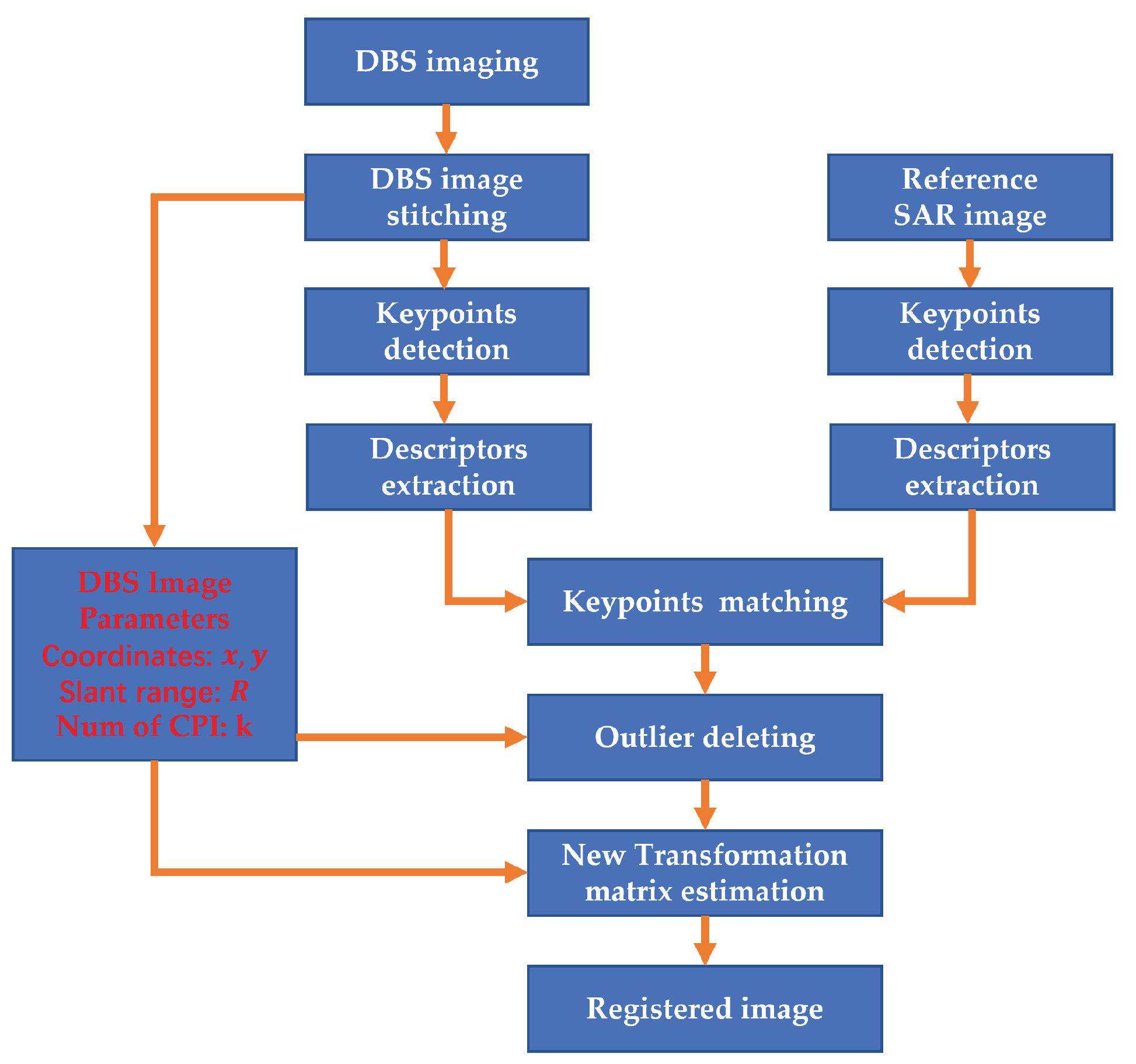
  • We first use the image registration method to register DBS images and SAR images for moving target relocation.
  • We propose a new matching algorithm to compensate for the match error between DBS images and SAR images. In the algorithm, we first analyze the geometric distortions of DBS images and add a negative second-order term of distance in the matching algorithm. Experimental results demonstrate that the proposed algorithm can indeed improve the accuracy of moving target relocation.
The remainder of the article is organized as follows. In Section 2, we first construct the ground-moving target relocation model. Furthermore, we analyze the problem of the SAR-SIFT algorithm used in image registration. Next, in Section 3, the geometric distortions of DBS images and SAR images are analyzed, and an improved matching algorithm is proposed in detail. Section 4 presents the simulated data and real data experimental results between the algorithms in the number of matched points and moving target relocation accuracy. Finally, the conclusions of this article are presented in Section 5.

2. Background

In this section, we first construct the ground-moving target relocation model and analyze the relocation errors caused by the platform’s parameters, especially the yaw angle, which can be non-negligible in a lightweight UAV-borne radar system. Next, we briefly introduce scanning DBS imaging, which is usually adopted to obtain wide-area surveillance and maintain a high revisit rate in the GMTI radar system. The image registration between the DBS image and the SAR image with coordinate information can be a feasible solution to improve the relocation accuracy in the UAV-borne GMTI radar system with low accuracy INS. Finally, we present the limitations when directly using image registration algorithms, like the SAR-SIFT algorithm.

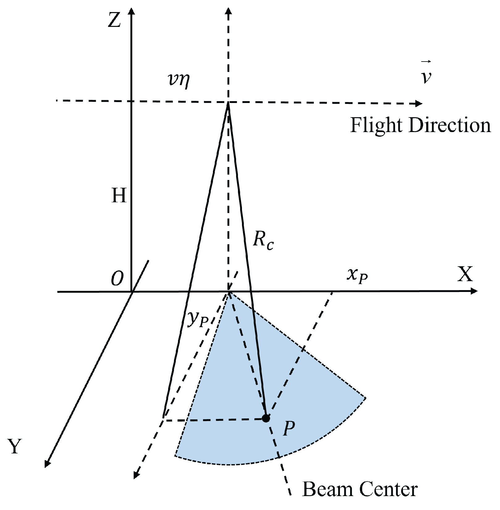
2.1. Moving Target Relocation Model

To analyze target relocation errors, we must first consider the geometry of the GMTI radar system, which is shown in Figure 1. In this figure, the X-axis points to the east, the Y-axis points to the north, and the Z-axis points to the top. The position of the UAV platform is ( x 0 , y 0 , z 0 ) , and the position of the ground-moving target P is ( x P , y P , z P ) . The flight direction v of the system is determined by the heading angle α , which is the angle between the north and the flight direction, while β is the angle between the direction of velocity of the UAV platform and the moving target P. Since the slant range R between the radar system and the moving target P can be estimated, the position of the ground-moving target P can then be expressed as follows [4]:
x P = x 0 + R 2 ( z 0 z P ) 2 · sin ( α β ) ,
y P = y 0 + R 2 ( z 0 z P ) 2 · cos ( α β ) .
Here, we assume that the region of the moving target P is flat and the altitude z P of the moving target P is the mean altitude of the region. Therefore, the position errors Δ x P and Δ y P can be expressed as follows:
Δ x P = x P x 0 Δ x 0 + x P R Δ R + x P z 0 Δ z 0 + x P z P Δ z P + x P α Δ α + x P β Δ β = Δ x 0 + sin ( α β ) R Δ R + ( z 0 z P ) ( Δ z 0 + Δ z P ) R 2 ( z 0 z P ) 2 + R 2 ( z 0 z P ) 2 cos ( α β ) ( Δ α + Δ β )
Δ y P = y P y 0 Δ y 0 + y P R Δ R + y P z 0 Δ z 0 + y P z P Δ z P + y P α Δ α + y P β Δ β = Δ y 0 + cos ( α β ) R Δ R + ( z 0 z P ) ( Δ z 0 + Δ z P ) R 2 ( z 0 z P ) 2 + R 2 ( z 0 z P ) 2 sin ( α θ ) ( Δ α + Δ β ) .
According to (3) and (4), the accuracy of the target position can be strongly affected by terms R 2 ( z 0 z P ) 2 cos ( α β ) ( Δ α + Δ β ) and R 2 ( z 0 z P ) 2 sin ( α β ) ( Δ α + Δ β ) due to the slant range R.
In the terms above, Δ β is the estimation accuracy of the moving target angle, which many researchers have sought to enhance. As for the estimation accuracy of the yaw angle, Δ α , the error can be as large as 0.28° in low-accuracy INSs, such as the micro-electromechanical systems (MEMSs) used in the differential global positioning system (DGPS) model [31]. Therefore, when the slant range R is 3 km, the position error caused by the yaw angle Δ α is about 14.67 m, which may place the moving target on an incorrect path. Thus, it is important for our lightweight UAV GMTI radar system to enhance the accuracy of target relocation.

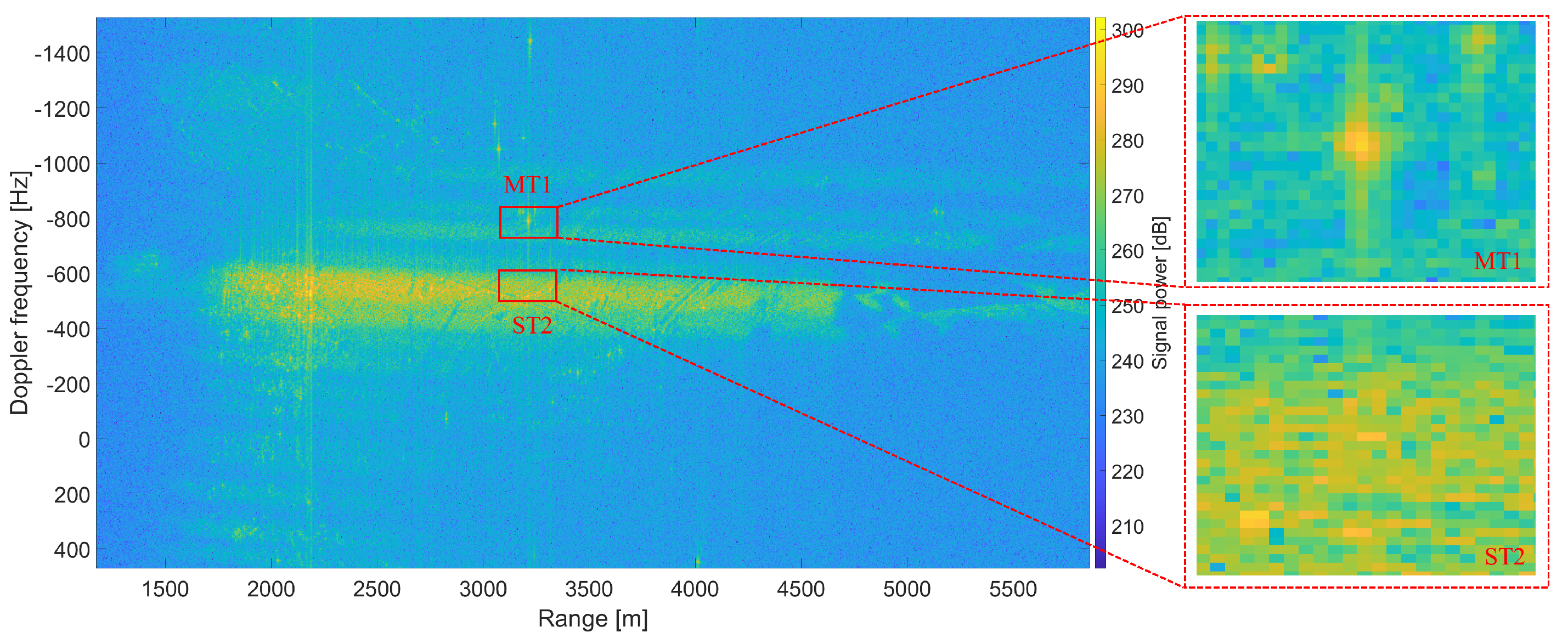
2.2. Doppler Beam Sharpening Image Acquisition and Stitching

When utilizing the SCAN-GMTI mode for wide-area surveillance, DBS technology can be employed to acquire large ground images, the imagery breadth of which is beyond that of traditional SAR technology. DBS imaging uses the Doppler spread caused by the movement of the UAV platform to differentiate echoes from various azimuths to achieve a finer azimuthal resolution than that with a real beam [32]. The geometric relationship between the UAV platform and ground scatter in the image region is illustrated in Figure 2.
According to this figure, the UAV flies along the X-axis with a velocity of v and height of H. For ground scatter A in the image region, the range of the pulsed compressed signal traveling from the radar system to A is then determined as follows:
s A ( τ , η ) = ω ( η ) sin c [ B ( t 2 R A ( η ) c ) ] exp [ j 4 π R A ( η ) λ ] ,
where τ is the fast time radar signal, η is the slow time radar signal, ω ( η ) represents the antenna window function, B is the signal bandwidth, c is the speed of light, and λ is the wavelength. The slant range R A ( η ) is the range between the radar system and the scatter A, which is expressed as follows:
R A ( η ) = ( x A v η ) 2 + y A 2 + H 2 R 0 x A v η R 0 = R 0 v η sin ψ cos θ ,
where R 0 = x A 2 + y A 2 + H 2 is the slant range at η = 0 , ψ is the pitching angle, and θ is the angle between the velocity direction and scatter A. The angle ϕ represents the direction of arrival (DOA) angle between the platform and scatter A, which is cos ϕ = sin ψ cos θ . Then, the Doppler frequency of the scatter A can be expressed as follows:
f d A = 2 v cos ϕ λ .
According to (7), the scatters observed at different DOA angles can be distinguished by the fast Fourier transform (FFT) algorithm because of their Doppler frequencies, which is the basic imaging principle behind DBS [33,34]. After FFT, the DBS image is displayed in a polar coordinate system, where the X-axis represents the slant range, and the Y-axis represents the Doppler frequency, as shown in Figure 3a. In order to observe this normally, the polar coordinate DBS image needs to be converted into a Cartesian coordinate image, as shown in Figure 3b. The transformation between the two coordinate systems is expressed as follows:
x = R cos ϕ = R f d λ 2 v ,
y = R 2 H 2 x 2 .
Usually, the DBS images in one coherent processing interval (CPI) are within the beam width of the antenna’s main lobe. Thus, the image registration between these DBS images and SAR images may result in significant errors in the azimuth direction. Therefore, DBS images from different beam directions need to be stitched into the corresponding geographic coordinate system to acquire large scenes. This process is known as DBS image stitching [35], which is shown in Figure 4. According to the Figure 4a, the crosshairs represent the common image pixels from diffrent DBS sub-images (Image 1 and Image 2). Usually, the DBS image stitching algorithm should align these crosshairs in the same region, as shown in the Figure 4b. If not, the ghosting and streaks will degrade the imaging quality of DBS images, and the image registration may fail.

2.3. Limitations in DBS-SAR Image Registration

As shown in Figure 5, the SAR-SIFT algorithm used in DBS-SAR image registration consists of three major stages [26]: key point detection, descriptor extraction, and key point matching.
During key point detection, multiscale representations of DBS and SAR images are first constructed using the SAR-Harris function at different scales. Then, the extrema in the space are labeled as the key points. Examples of key point detection in a DBS image and an SAR image are shown in Figure 6. As shown in the figure, the key points detected in these images are mostly located on corners and lines, which aligns with the expected results of the SAR-SIFT algorithm.
Then, the dominant orientations are calculated for each key point from a local orientation histogram corresponding to a circular neighborhood. The descriptor of each orientation, called the ratio descriptor, is then determined based on the histograms of the gradient orientation. Next, the key points of two different images are matched using the nearest neighbor distance ratio (NNDR). Figure 7 illustrates the matching result achieved with the SAR-SIFT algorithm for DBS-SAR image registration.
Since the initial matching result of the DBS-SAR image registration contains false matches due to the relaxed threshold, it is important to eliminate these outliers, which is commonly achieved with the SAR-SIFT algorithm using the affine transformation and random sample consensus (RANSAC) algorithms [36]. Next, in a homogeneous coordinate system, the affine transformation can be expressed as follows:
x y 1 = a 11 a 12 a 13 a 21 a 22 a 23 0 0 1 · x y 1 ,
where ( x , y ) are the coordinates of the sensed image, ( x , y ) are the coordinates of the reference image, and a i j are the transformation parameters. The transformation parameters can be estimated according to the least squares (LS) algorithm.
However, the combination of the affine transformation and RANSAC algorithms does not exhibit superior performance regarding DBS-SAR image registration. Figure 8 illustrates the filtered matching results achieved for DBS-SAR image registration. Compared to the initial matching results, the filtered results miss a large number of correctly matched points.
In addition, the filtered results are predominantly clustered in one region of the image and lead to less-matched regions in the registered DBS image. Figure 9 illustrates the fused image obtained using the filtered results and enlarged images of the less-matched regions. In these regions, the paths in the DBS image (green solid lines) and the SAR image (yellow solid lines) exhibit a significant offset. Thus, this matching algorithm reduces the positioning accuracy of ground-moving target relocation. Therefore, it is important to propose a new matching algorithm for DBS and SAR images.

3. An Improved Matching Algorithm for DBS Images and SAR Images

As demonstrated in Section 2.3, it is important to construct an optimal geometric transformation algorithm for DBS-SAR image registration. Therefore, in this section, we first analyze the geometric distortions in SAR and DBS images. Then, based on the results of that analysis, we propose an improved matching algorithm.

3.1. Geometric Distortions in SAR Images and DBS Images

As one of the most widely used SAR imaging algorithms, the range Doppler (RD) algorithm describes the geometry of the imaging displayed in Figure 10. After using the range cell migration correction (RCMC) algorithm to correct the geometric distortion in an SAR image, the coordinate of the scatter P ( x P , y P , z P ) in the SAR image region is expressed as follows:
x P = v η + x c = v η + λ R c 2 v f d c ,
y P = R c 2 ( H z P ) 2 x c 2 ,
where v is the velocity of the UAV platform, η is the slow time radar signal, R c is the slant range at the beam center, and f d c is the Doppler frequency of the beam center. Here, we assume that the information contained in the digital elevation model (DEM) is known.
According to Equations (11) and (12), the errors Δ x P and Δ y P of scatter P in the SAR image are calculated by applying the following error propagation model:
Δ x P = x P v Δ v + x P η Δ η + x P f d c Δ f d c + x P R c Δ R c + x P λ Δ λ = ( η + λ f d c R c 2 v 2 ) Δ v + v Δ η + λ R c 2 v Δ f d c + λ f d c 2 v Δ R c + + f d c R c 2 v Δ λ = η Δ v + v Δ η + Δ x c ,
Δ y P = y P x c Δ x c + y P R c Δ R c + y P H Δ H = 1 y P ( R c Δ R c + x c Δ x c + ( H z P ) Δ H ) .
In Equation (13), the terms v Δ η and Δ x c are considered approximately constant over a period of time. Thus, Equation (13) is linearly related to speed v. In Equation (14), compared to the slant range R c , variables x c and H z P are much smaller than y P . Thus, Equation (14) is related to the slant range error. Therefore, the affine transformation can achieve SAR image registration.
As for the geometric distortion in DBS images, according to Equations (8) and (9), errors Δ x A and Δ y A of scatter A in the DBS image are calculated as follows:
Δ x A = x A f d A Δ f d + x A R A Δ R A + x A v Δ v + x A λ Δ λ = λ R A 2 v Δ f d + λ f d A 2 v Δ R A + λ f d A R A 2 v 2 Δ v + f d A R A 2 v Δ λ = x A ( Δ R A R A + Δ v v + Δ λ λ ) + λ R A 2 v Δ f d ,
Δ y A = y A x A Δ x A + y A R A Δ R A + y A H Δ H = 1 y A ( R A Δ R A + x A Δ x A + ( H z A ) Δ H ) = 1 y A ( R A Δ R A + x A 2 ( Δ R A R A + Δ v v + Δ λ λ ) + x A λ R A 2 v Δ f d + ( H z A ) Δ H ) .
Since the velocity error and the range error are the main factors contributing to DBS imaging errors, Equations (15) and (16) can then be simplified to the following:
Δ x A x A Δ v v ,
Δ y A 1 y A ( R A Δ R + x A 2 Δ v v ) .
According to these equations, the errors in a DBS image are different from the errors in an SAR image, and the most important difference is in the term x A 2 y A Δ v v in Δ y A errors. Thus, the direct use of the affine transformation, a linear transformation, does not perform well in DBS-SAR image matching.

3.2. The New Matching Algorithm

To improve the matching result, our proposed matching algorithm should account for the effect of DBS imaging errors on image registration. In this section, we detail how our algorithm achieves this. Assuming that the radar coordinates in the east–north–up (ENU) coordinate system are ( x r , y x , z r ) and the flight direction of the radar is α (the angle between the northward direction and the flight direction), the coordinates ( x A , y A , z A ) of target A within this system are determined as follows:
x A y A = sin α cos α cos α sin α x A y A + x r y r .
By considering the position errors Δ x A and Δ y A from (17) and (18), Equation (19) can be expressed as follows:
x A y A = sin α cos α cos α sin α x A + Δ x A y A + Δ y A + x r y r = sin α cos α cos α sin α x A + x A Δ v v y A + 1 y A ( R A Δ R + x A 2 Δ v v ) + x r y r = ( 1 + Δ v v ) sin α cos α Δ R cos α Δ v v cos α x r ( 1 + Δ v v ) cos α sin α Δ R sin α Δ v v sin α y r x A y A R A y A x A 2 y A 1 .
In addition, for a DBS image in a different CPI, Equation (20) should be rewritten as follows:
x A y A = sin α cos α cos α sin α x A + k v η C P I + Δ x A y A + Δ y A + x r y r = ( 1 + Δ v v ) sin α v η C P I sin α cos α Δ R cos α Δ v v cos α x r ( 1 + Δ v v ) cos α v η C P I cos α sin α Δ R sin α Δ v v sin α y r x A k y A R A y A x A 2 y A 1 ,
where k is the number of CPIs, and η C P I is the duration of one CPI. Finally, a new transformation matrix can be used to improve the matching performance of our proposed method compared to that of other matching algorithms. As for the parameters in the transformation matrix, the LS estimation of their coefficients can be used to correct the corresponding DBS-SAR image registration.
A flowchart of the proposed matching algorithm is shown in Figure 11. First, the DBS image is constructed from raw radar data using DBS imaging and the stitching algorithm. The parameters of the DBS image are also extracted by this algorithm for use in subsequent steps. Next, the key points are detected in both the DBS image and the reference SAR image using the SAR-Harris algorithm at different scales. Then, the dominant orientations and descriptors of key points are determined. Later, the key points of two images are matched, according to their descriptors, using the NNDR algorithm. However, many mismatched points are obtained with the classic matching algorithm, which leads to an incorrect registered image. Therefore, we propose using the RANSAC algorithm and our new DBS transformation matrix to eliminate these outliers. In addition, the parameters of the DBS image, such as the slant range R, the number of CPIs k, and the coordinates in the image, are used to obtain a high number of correct matches with a low false alarm rate. Finally, the transformation matrix is determined using the correct matches and then employed to register the DBS image.

4. Experimental Results

In this section, the performance of the improved matching algorithm for DBS-SAR image registration was investigated using simulated and experimental data. The experimental data were obtained using an advanced UAV-borne GMTI radar system with a Ku band, as shown in Figure 12. The radar was specifically designed by our team for GMTI experiments and is equipped with a dual-channel phased array antenna. Table 1 displays the main parameters of the radar system. To ensure the validity of our comparison of the algorithm’s performance, the simulation parameters were kept the same as the experimental parameters.
Furthermore, the proposed matching algorithm was compared with the affine transformation and second-order polynomial algorithms, both of which are frequently used in SAR image registration.

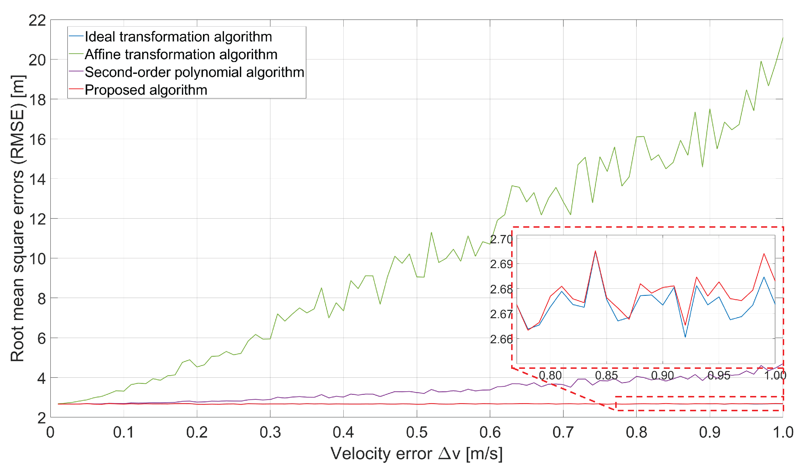
4.1. Simulated Image Registration Experiment

In the simulated experiment, we first constructed positioning errors in the matched points taken from the DBS image and the true coordinates by adding the radar parameter error values shown in Table 2.
Figure 13 illustrates the positioning errors of the matching points with and without the velocity error. By comparing the figures, it can be seen that the positioning errors of matched points in the DBS image have an almost random distribution when the velocity error is not considered. However, when the velocity error is added, the distribution of the position errors then approximates the form of a parabola. This result is consistent with the analysis of the DBS image errors in Section 3.1.
As positioning errors have a parabolic distribution, as shown in Figure 13b, the second-order polynomial transformation algorithm used to compare them is expressed as follows:
x A y A = a 1 a 2 a 3 a 4 a 5 a 6 b 1 b 2 b 3 b 4 b 5 b 6 x A y A x A 2 y A 2 x A y A 1 .
To thoroughly validate the effectiveness of the proposed algorithm, we conducted Monte Carlo experiments to examine the improvement in the algorithm’s position error under different speed error conditions.
In addition, we performed another Monte Carlo experiment (times = 200) to compare the position error obtained using the proposed algorithm, as well as the affine transformation, second-order polynomial, and ideal transformation algorithms with and without a velocity error, as shown in Figure 14. According to this figure, the affine transformation algorithm performed worst, with its root mean square error (RMSE) increasing rapidly with the introduction of the velocity error. The second-order polynomial algorithm performed better, and while its RMSE also increased with the velocity error, it did not increase rapidly. Compared to the matching algorithms mentioned above, our proposed algorithm achieved the best transformation matrix estimation; its RMSE was close to that of the ideal transformation algorithm without a velocity error and did not increase with the velocity error. Our proposed algorithm first accounted for the sectorial geometric distortion in the DBS image and incorporated this distortion into the transformation matrix through the term x 2 / y . Hence, our proposed transformation algorithm showed the best performance in transformation matrix estimation.

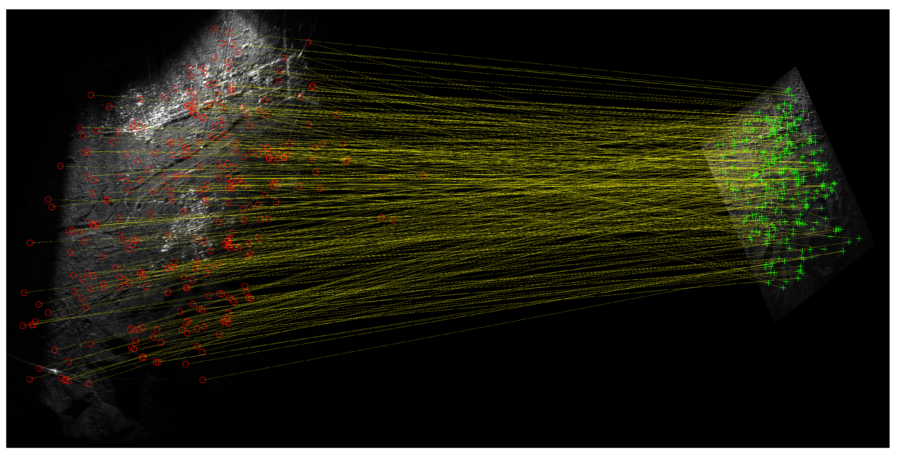
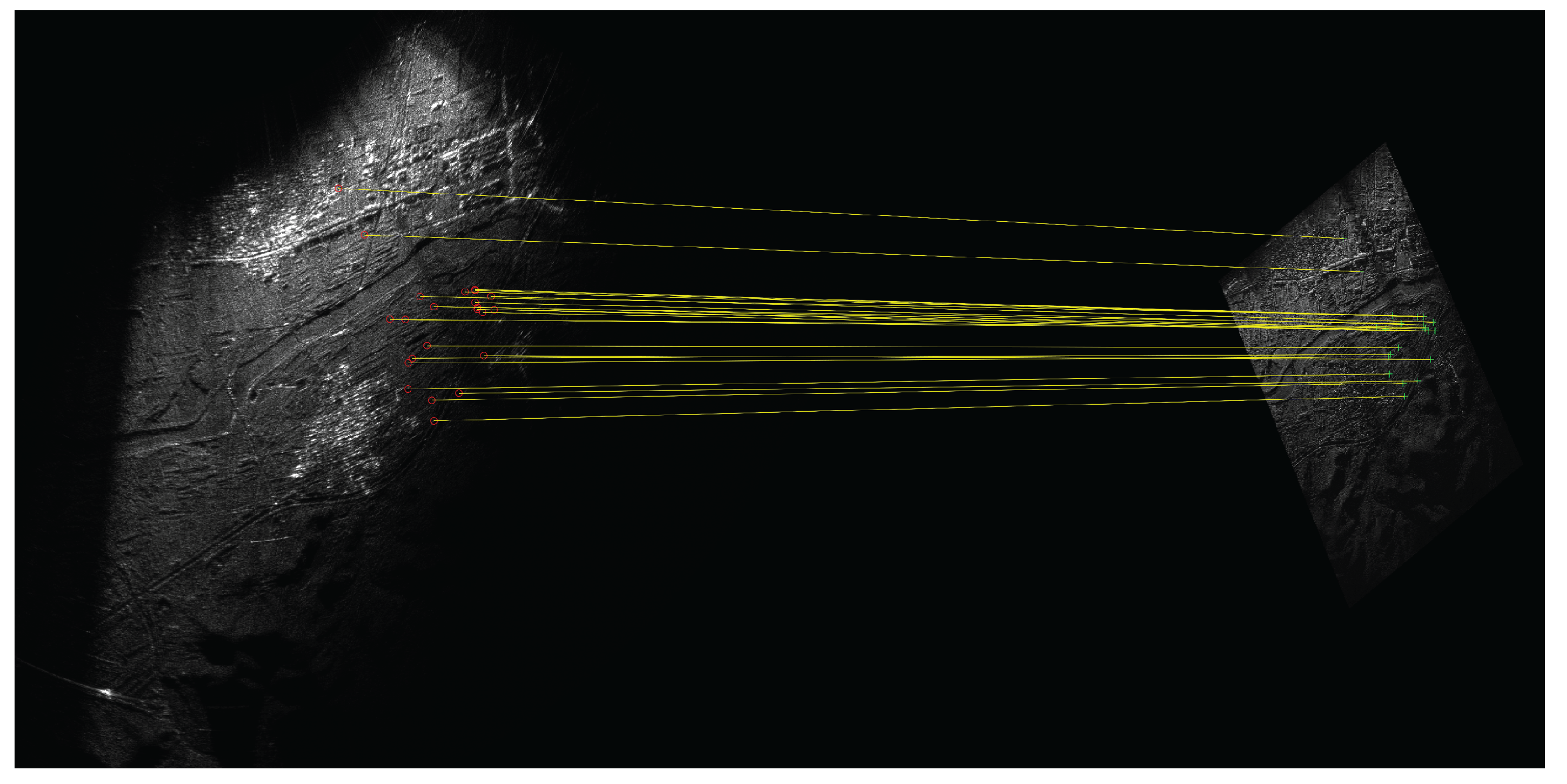
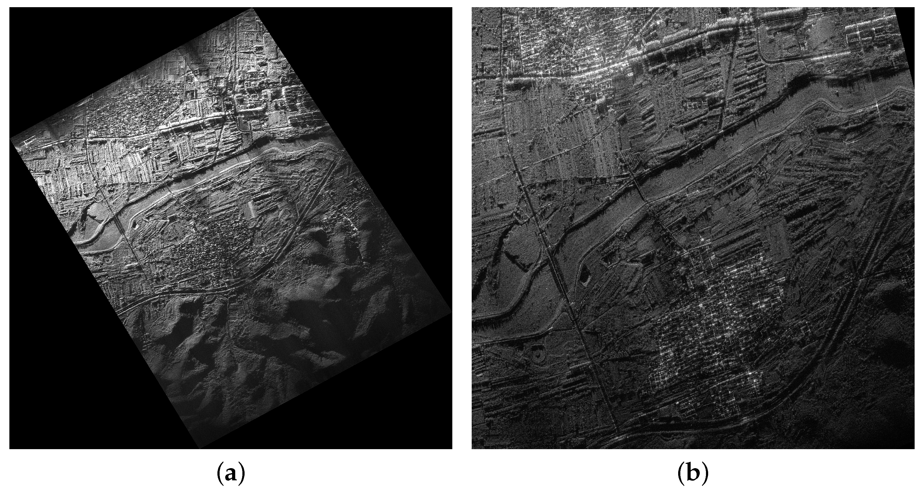
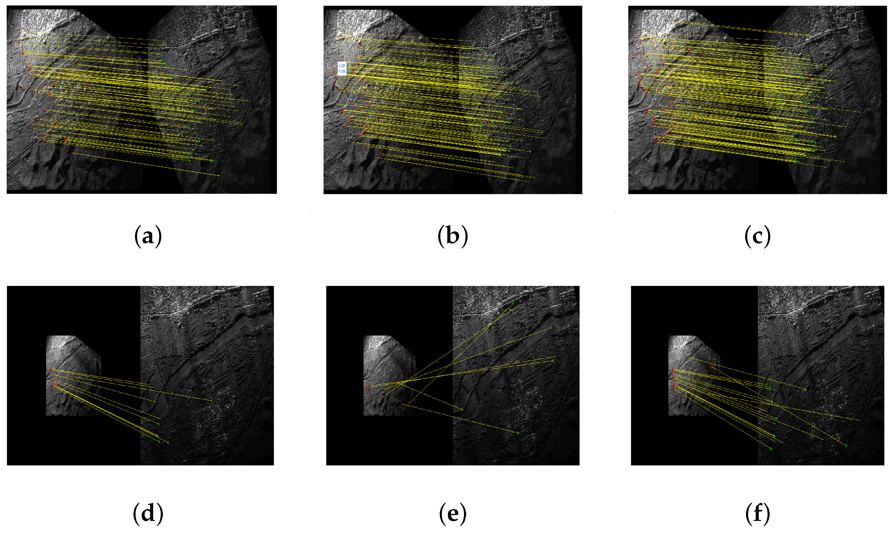
4.2. Comparison of the Algorithms Within a Real-World Experiment

A flight was conducted in June 2022 over Pinggu, Beijing, China. Figure 15 includes an image of the test site. A cooperative car, MT1, and a corner reflector, ST2, were positioned within the region of interest (ROI). The position of the corner reflector and the path of the cooperative car were recorded using handheld GPS devices.
During the experiment, the UAV platform flew along a designated flight path over the test region, maintaining a constant speed. Figure 16 shows the DBS images of the test region from the seventh scan cycle, as well as a reference SAR image for image registration.
As for the reference SAR image for image registration, both images were acquired by the same SAR system equipped with high-accuracy INS. Figure 17 illustrates the SAR images of the test region with different incidence angles. The SAR image from the experiment in 2022 has an incidence angle of 68°, while the SAR image from the experiment in 2023 has an incidence angle of 74°.
To validate the effectiveness of the proposed matching algorithm, we compared its results to those of the affine transformation and second-order polynomial algorithms. The matching results of these algorithms, taken from the seventh scan cycle of the DBS image, are shown in Figure 18 and Figure 19. The affine algorithm yielded the fewest matched key points, with most of them concentrated within the DBS image from a single scan cycle. As for the second-order algorithm, while the single scan cycle issue was largely alleviated, many key points remained unmatched. In comparison, the proposed algorithm yielded the highest number of matched key points, which also formed the most widely distributed DBS image.
Furthermore, to quantitatively demonstrate the improvement achieved with the proposed algorithm, we used the number of matched points and RMSE as the evaluation metrics to compare the algorithms, and the results of this comparison are demonstrated in Table 3 and Table 4. As can be seen, the number of matched points using our proposed algorithm improved by 86.5 % and 41.7 % compared to the affine transformation and second-order polynomial algorithms, respectively, while the RMSE values of all algorithms were close.
In addition, we also evaluated the performance of our proposed algorithm in ground moving target relocation. Figure 20 shows the DBS image of one CPI and enlarged images of MT1 and ST2, both of which are highlighted by the red boxes in the larger image.
Before evaluating the position estimation accuracy of our proposed algorithm, the cooperative moving target needed to be detected and relocated in the DBS image. To accomplish this, the clutter suppression interferometry (CSI) algorithm [38] was used for clutter suppression, and the relocation algorithm was adopted from [39]. Figure 21 shows the relocation result for the cooperative moving target in the DBS image. In the figure, the relocated position of the cooperative moving target is closely aligned with the ground truth positions.
Finally, the position errors for MT1 and ST2 obtained with different matching algorithms are summarized in Table 5. This table shows that when using the affine transformation, absolute position errors were found to be larger than 50 m. Although the second-order polynomial algorithm led to reduced position errors, it still exhibited significant relocation errors. In comparison, since the proposed algorithm accounts for the unique geometric distortion in the DBS image, its absolute position errors were significantly decreased. This positioning accuracy highlights the potential of the proposed algorithm for monitoring moving targets in a UAV-borne GMTI radar system.

5. Discussion

Our proposed DBS-SAR image registration algorithm leads to a great improvement in the accuracy of moving target relocation tracking in UAV-borne GMTI radar systems. We first analyzed the limitations of the conventional image registration algorithm used for DBS-SAR image registration. Next, we analyzed the geometric distortion in DBS and SAR images. To improve DBS-SAR image registration, we employed a new matching algorithm that compensated for the unique geometric distortion in DBS imaging.
The performance of the proposed algorithm was verified using simulated and experimental data. In the simulated experiment, the RMSE of our proposed algorithm was close to that of the ideal transformation algorithm and significantly better than that of other matching algorithms. In the real-world experiment, the number of matched key points identified using our proposed algorithm was 86.5% and 41.7% higher than the number identified using the affine transformation and second-order polynomial algorithms, while the RMSE values of all the algorithms were close. In addition, we also evaluated the performance of our proposed algorithm in moving target relocation tracking. The experiment results indicate that the relocation accuracy of our proposed algorithm improved by 68.2% and 36.9% compared to that of the affine transformation and second-order polynomial algorithms, respectively. This result aligns with those of prior studies highlighting the improved performance of the proposed algorithm in high-accuracy moving target relocation tracking without a high-precision INS.
Despite its advantages, the main limitation of the proposed algorithm is that the geometric distortion model proposed for correcting DBS images may fail in complex flights. In addition, DBS-SAR image registration is time-consuming for edge devices such as UAV-borne GMTI radar systems, which introduces additional complexity to real-time GMTI systems.
Hence, in future research, we will focus on solving the limitations and challenges associated with our proposed algorithm. We plan to test our algorithm in other terrains to develop adaptive DBS-SAR image registration. Furthermore, a method for onboard hardware acceleration (e.g., an FPGA) may also be added to reduce latency and improve the performance of the proposed algorithm.

6. Conclusions

In this study, a novel matching algorithm for DBS-SAR image registration was proposed. The algorithm works with DBS images and is suitable for implementation on UAV platforms, especially those with low-accuracy INS. Our proposed algorithm is innovative in its compensation of the geometric distortion in DBS images. The experimental results from both simulated and real-world data revealed that the proposed algorithm is suitable for DBS-SAR image registration. It achieved comparatively better position accuracy and more correct matches in the features it identified than those of the affine transformation and second-order polynomial algorithms.
The proposed algorithm can theoretically be used to register any DBS and SAR images without velocity parameters. In further studies, we plan to evaluate the use of this algorithm in UAV navigation.

Author Contributions

Conceptualization, W.L., X.L., X.B. and Y.L. (Yanlei Li); methodology, W.L.; software, W.L., Z.C., Z.J. and Y.L. (Yunlong Liu); validation, W.L., Z.C., Y.L. (Yanlei Li), and Y.L. (Yunlong Liu); formal analysis, W.L.; investigation, W.L. and Z.C.; resources, X.L.; data curation, W.L., Z.C., X.B., Y.L. (Yunlong Liu), and Z.J.; writing—original draft preparation, W.L.; writing—review and editing, W.L., Y.L. (Yanlei Li), and X.L.; visualization, W.L.; supervision, X.L.; project administration, X.L.; funding acquisition, X.B., Y.L. (Yanlei Li), and X.L. All authors have read and agreed to the published version of the manuscript.

Funding

This research received no external funding.

Data Availability Statement

The data presented in this study are available on request from the corresponding author.

Conflicts of Interest

The authors declare no conflicts of interest.

Abbreviations

The following abbreviations are used in this manuscript:
UAVunmanned aerial vehicle
GMTIground-moving target indication
SWaPsize, weight, and power
INSinertial navigation system
DBSDoppler beam sharpening
SARsynthetic aperture radar
SIFTscale-invariant feature transform
DOSdirection-of-arrival
DCBdigital channel balancing
KBknowledge-based
PPSpolynomial phase signal
SWTstationary wavelet transform
HORGhistogram of oriented ratio gradient
RCPrational polynomial coefficient
MEMSmicro-electro-mechanical system
DGPSdifferential global positioning system
CPIcoherent processing time
NNDRnearest neighbor distance ratio
RANSACrandom sample consensus
LSleast square
DEMdigital elevation mode
ENUEast–North–Up
RMSEroot mean square error
ROIregion of interest
CSIclutter suppression interferometry

References

  1. Entzminger, J.N.; Fowler, C.A.; Kenneally, W.J. JointSTARS and GMTI: Past, present and future. IEEE Trans. Aerosp. Electron. Syst. 1999, 35, 748–761. [Google Scholar] [CrossRef]
  2. Chang, C.Y.; Woo, A.; Forry, H.; Sherman, J.; Recht, M.; Clark, R.; Levin, R. HISAR-300: An Advanced Airborne Multi-Mission Surveillance Radar. In Proceedings of the 2019 IEEE Radar Conference (RadarConf), Boston, MA, USA, 22–26 April 2019; pp. 1–6. [Google Scholar]
  3. Greenspan, M. Joint STARS—The Start of 50 Years of All Speed Surface Moving Target Detection and Tracking. IEEE Aerosp. Electron. Syst. Mag. 2023, 38, 32–37. [Google Scholar] [CrossRef]
  4. Cerutti-Maori, D.; Klare, J.; Brenner, A.R.; Ender, J.H.G. Wide-Area Traffic Monitoring with the SAR/GMTI System PAMIR. IEEE Trans. Geosci. Remote Sens. 2008, 46, 3019–3030. [Google Scholar] [CrossRef]
  5. Silva, A.B.C.d.; Baumgartner, S.V. A Priori Knowledge-Based STAP for Traffic Monitoring Applications: First Results. In Proceedings of the EUSAR 2016: 11th European Conference on Synthetic Aperture Radar, Hamburg, Germany, 6–9 June 2016; pp. 1–5. [Google Scholar]
  6. Chen, J.; An, D.; Ge, B.; Zhou, Z. Detection, Parameters Estimation, and Imaging of Moving Targets Based on Extended Post-Doppler STAP in Multichannel WasSAR-GMTI. IEEE Trans. Geosci. Remote Sens. 2024, 62, 5223515. [Google Scholar] [CrossRef]
  7. Budillon, A.; Pascazio, V.; Schirinzi, G. Estimation of Radial Velocity of Moving Targets by Along-Track Interferometric SAR Systems. IEEE Geosci. Remote Sens. Lett. 2008, 5, 349–353. [Google Scholar] [CrossRef]
  8. Barros Cardoso da Silva, A.; Baumgartner, S.V.; de Almeida, F.Q.; Krieger, G. In-Flight Multichannel Calibration for Along-Track Interferometric Airborne Radar. IEEE Trans. Geosci. Remote Sens. 2021, 59, 3104–3121. [Google Scholar] [CrossRef]
  9. Barros Cardoso da Silva, A.; Joshi, S.K.; Baumgartner, S.V.; de Almeida, F.Q.; Krieger, G. Phase Correction for Accurate DOA Angle and Position Estimation of Ground-Moving Targets Using Multi-Channel Airborne Radar. IEEE Geosci. Remote Sens. Lett. 2022, 19, 4021605. [Google Scholar] [CrossRef]
  10. Gierull, C.H. Digital Channel Balancing of Along-Track Interferometric SAR Data; Defence R & D Canada-Ottawa: Ottawa, ON, Canada, 2003. [Google Scholar]
  11. Ruixian, H.; Baochang, L.; Tong, W.; Dongdong, L.; Zheng, B. A Knowledge-Based Target Relocation Method for Wide-Area GMTI Mode. IEEE Geosci. Remote Sens. Lett. 2014, 11, 748–752. [Google Scholar] [CrossRef]
  12. Huang, P.; Xia, X.-G.; Wang, L.; Xu, H.; Liu, X.; Liao, G.; Jiang, X. Imaging and Relocation for Extended Ground Moving Targets in Multichannel SAR-GMTI Systems. IEEE Trans. Geosci. Remote Sens. 2022, 60, 5214024. [Google Scholar] [CrossRef]
  13. Svedin, J.; Bernland, A.; Gustafsson, A.; Claar, E.; Luong, J. Small UAV-based SAR system using low-cost radar, position, and attitude sensors with onboard imaging capability. Int. J. Microw. Wirel. Technol. 2021, 13, 602–613. [Google Scholar] [CrossRef]
  14. Nitti, D.O.; Bovenga, F.; Chiaradia, M.T.; Greco, M.; Pinelli, G. Feasibility of Using Synthetic Aperture Radar to Aid UAV Navigation. Sensors 2015, 15, 18334–18359. [Google Scholar] [CrossRef] [PubMed]
  15. Wellig, P.; Speirs, P.; Schuepbach, C.; Oechslin, R.; Renker, M.; Boeniger, U.; Pratisto, H. Radar Systems and Challenges for C-UAV. In Proceedings of the 2018 19th International Radar Symposium (IRS), Bonn, Germany, 20–22 June 2018; pp. 1–8. [Google Scholar]
  16. Catapano, I.; Gennarelli, G.; Ludeno, G.; Noviello, C.; Esposito, G.; Renga, A.; Fasano, G.; Soldovieri, F. Small Multicopter-UAV-Based Radar Imaging: Performance Assessment for a Single Flight Track. Remote Sens. 2020, 12, 774. [Google Scholar] [CrossRef]
  17. Sun, B.M.; Kenney, R.H.; Yeary, M.B.; Sigmarsson, H.H.; McDaniel, J.W. Reduced Navigation Error Using a Multi-Sensor Fusion Technique and Its Application in Synthetic Aperture Radar. IEEE J. Microwaves 2024, 4, 86–100. [Google Scholar] [CrossRef]
  18. Meng, K.; Wu, Q.; Xu, J.; Chen, W.; Feng, Z.; Schober, R.; Swindlehurst, A.L. UAV-Enabled Integrated Sensing and Communication: Opportunities and Challenges. IEEE Wirel. Commun. 2024, 31, 97–104. [Google Scholar] [CrossRef]
  19. Zhang, R.; Wu, W.; Chen, X.; Gao, Z.; Cai, Y. Terahertz Integrated Sensing and Communication-Empowered UAVs in 6G: A Transceiver Design Perspective. IEEE Veh. Technol. Mag. 2025, 2–11. [Google Scholar] [CrossRef]
  20. Šipoš, D.; Gleich, D. A Lightweight and Low-Power UAV-Borne Ground Penetrating Radar Design for Landmine Detection. Sensors 2020, 20, 2234. [Google Scholar] [CrossRef]
  21. Zhang, L.; Qiao, Z.; Xing, M.-D.; Yang, L.; Bao, Z. A Robust Motion Compensation Approach for UAV SAR Imagery. IEEE Trans. Geosci. Remote Sens. 2012, 50, 3202–3218. [Google Scholar] [CrossRef]
  22. Hu, X.; Ma, C.; Hu, R.; Yeo, T.S. Imaging for Small UAV-Borne FMCW SAR. Sensors 2019, 19, 87. [Google Scholar] [CrossRef]
  23. Huang, Y.; Liu, F.; Chen, Z.; Li, J.; Hong, W. An Improved Map-Drift Algorithm for Unmanned Aerial Vehicle SAR Imaging. IEEE Geosci. Remote Sens. Lett. 2021, 18, 1–5. [Google Scholar] [CrossRef]
  24. Wang, G.; Feng, L.; Li, J.; Xing, T.; Ma, C.; Kang, C. A Robust Image Stitching and Geometric Correction Method for Doppler Beam Sharpening Imaging. In Proceedings of the 2019 6th Asia-Pacific Conference on Synthetic Aperture Radar (APSAR), Xiamen, China, 26–29 November 2019; pp. 1–4. [Google Scholar]
  25. Lowe, D.G. Distinctive Image Features from Scale-Invariant Keypoints. Int. J. Comput. Vis. 2004, 60, 91–110. [Google Scholar] [CrossRef]
  26. Dellinger, F.; Delon, J.; Gousseau, Y.; Michel, J.; Tupin, F. SAR-SIFT: A SIFT-Like Algorithm for SAR Images. IEEE Trans. Geosci. Remote Sens. 2015, 53, 453–466. [Google Scholar] [CrossRef]
  27. Jianwei, F.; Yan, W.; Fan, W.; Qiang, Z.; Guisheng, L.; Ming, L. SAR Image Registration Using Phase Congruency and Nonlinear Diffusion-Based SIFT. IEEE Geosci. Remote Sens. Lett. 2015, 12, 562–566. [Google Scholar] [CrossRef]
  28. Fan, J.; Wu, Y.; Li, M.; Liang, W.; Zhang, Q. SAR Image Registration Using Multiscale Image Patch Features With Sparse Representation. IEEE J. Sel. Top. Appl. Earth Obs. Remote Sens. 2017, 10, 1483–1493. [Google Scholar] [CrossRef]
  29. Paul, S.; Pati, U.C. SAR Image Registration Using an Improved SAR-SIFT Algorithm and Delaunay-Triangulation-Based Local Matching. IEEE J. Sel. Top. Appl. Earth Obs. Remote Sens. 2019, 12, 2958–2966. [Google Scholar] [CrossRef]
  30. Chang, Y.; Xu, Q.; Xiong, X.; Jin, G.; Hou, H.; Man, D. SAR image matching based on rotation-invariant description. Sci. Rep. 2023, 13, 14510. [Google Scholar] [CrossRef] [PubMed]
  31. APX-15. Available online: https://www.applanix.com/cn/products/dg-uavs.htm (accessed on 23 February 2025).
  32. Wang, B.; Song, C.; Liu, N.; Liu, Z.; Zhou, L.; Xiang, M. An Advanced Lightweight Dual-Band Digital Array SAR System: Earth Observation Imaging and Moving Target Detection. IEEE Sens. J. 2023, 23, 21776–21786. [Google Scholar] [CrossRef]
  33. Chen, H.; Li, M.; Zhang, P.; Liu, G.; Jia, L.; Wu, Y. Resolution enhancement for Doppler beam sharpening imaging. Iet Radar Sonar Navig. 2015, 9, 843–851. [Google Scholar] [CrossRef]
  34. Mao, D.; Zhang, Y.; Zhang, Y.; Huang, Y.; Yang, J. Doppler Beam Sharpening Using Estimated Doppler Centroid Based on Edge Detection and Fitting. IEEE Access 2019, 7, 123604–123615. [Google Scholar] [CrossRef]
  35. Chen, H.; Li, M.; Lu, V.; Wu, Y. A DBS image stitching algorithm based on affine transformation. In Proceedings of the IET Conference Proceedings, Xi’an, China, 14–16 April 2013. [Google Scholar]
  36. Fischler, M.A.; Bolles, R.C. Random sample consensus. Commun. ACM 1981, 24, 381–395. [Google Scholar] [CrossRef]
  37. Smith, D.; Atkinson, S.F. Accuracy of rectification using topographic map versus GPS ground control points. Photogramm. Eng. Remote Sens. 2001, 67, 565–570. [Google Scholar]
  38. Deming, R.W.; MacIntosh, S.; Best, M. Three-channel processing for improved geo-location performance in SAR-based GMTI interferometry. In Proceedings of the Algorithms for Synthetic Aperture Radar Imagery XIX, Baltimore, MD, USA, 23–26 April 2012; p. 83940F. [Google Scholar]
  39. Liu, W.; Zhang, Y.; Ge, X.; Li, Y.; Liu, Y.; Bu, X.; Liang, X. An Improved Knowledge-Based Ground Moving Target Relocation Algorithm for a Lightweight Unmanned Aerial Vehicle-Borne Radar System. Remote Sens. 2025, 17, 1182. [Google Scholar] [CrossRef]
Figure 1. The geometry of the ground-moving target relocation model in the UAV-borne GMTI radar system.
Electronics 14 01760 g001
Figure 2. The geometry of the UAV platform and ground scatter A in the DBS image.
Electronics 14 01760 g002
Figure 3. Illustration of the DBS image in one coherent time(CPI). (a) DBS image in polar coordinates. (b) DBS image in Cartesian coordinates.
Electronics 14 01760 g003
Figure 4. Illustrations of DBS image stitching: (a) a geometric model of DBS image stitching; (b) the result of DBS image stitching.
Electronics 14 01760 g004
Figure 5. A simplified flowchart of DBS-SAR image registration.
Electronics 14 01760 g005
Figure 6. Key point detection results in (a) a DBS image and (b) an SAR image using the SAR-Harris function.
Electronics 14 01760 g006
Figure 7. The key point matching result of the SAR-SIFT algorithm for DBS-SAR image registration. In the figure, the red circles and green crosshairs represent the matched key points in the DBS image and SAR image.
Electronics 14 01760 g007
Figure 8. The filtered matching result in DBS-SAR image registration using a threshold value of 5.
Electronics 14 01760 g008
Figure 9. The fused image of DBS-SAR image registration, where red dashed rectangles indicate less-matched regions.
Electronics 14 01760 g009
Figure 10. The geometry of SAR imaging using the RD algorithm.
Electronics 14 01760 g010
Figure 11. A flowchart of the proposed matching algorithm for DBS-SAR image registration. The parameters of the DBS image are extracted in order to remove outliers and establish a new transformation matrix.
Electronics 14 01760 g011
Figure 12. The UAV-borne GMTI radar system.
Electronics 14 01760 g012
Figure 13. Positioning errors of the matching points in DBS images for the simulated experiment in the cross−range: (a) the positioning errors calculated without the velocity error; (b) the positioning errors calculated with the velocity error.
Electronics 14 01760 g013
Figure 14. Comparison of the position errors obtained using different matching algorithms with respect to the velocity error.
Electronics 14 01760 g014
Figure 15. A real-world experiment with a cooperative moving car. The car moved within the ROI (orange box), and its path was recorded using a handheld GPS device.
Electronics 14 01760 g015
Figure 16. The DBS images of the test region with the GMTI radar system. (a) The 7th scan cycle of the DBS image for the experiment in 2022. (b) The 7th scan cycle of the DBS image for the experiment in 2023.
Electronics 14 01760 g016
Figure 17. The reference SAR image of the test region obtained by our experimental SAR system equipped with high-accuracy INS. (a) The reference SAR image from the experiment in 2022 with 0.5 m resolution and a 68° incidence angle. (b) The reference SAR image from the experiment in 2023 with 0.5 m resolution and a 74° incidence angle.
Electronics 14 01760 g017
Figure 18. Comparison of different matching algorithms in the 7th scan cycle of the DBS image (left) in 2022 and reference SAR images (right): (ac) the matching results of the DBS image and the SAR image in 2022 with (a) the affine transformation algorithm, (b) the second-order polynomial algorithm, and (c) the proposed algorithm; (df) the matching results of the DBS image and the SAR image in 2023 with (a) the affine transformation algorithm, (b) the second-order polynomial algorithm, and (c) the proposed algorithm.
Electronics 14 01760 g018
Figure 19. Comparison of different matching algorithms in the 7th scan cycle of the DBS image (left) in 2023 and reference SAR images (right): (ac) the matching results of the DBS image and the SAR image in 2022 with (a) the affine transformation algorithm, (b) the second-order polynomial algorithm, and (c) the proposed algorithm; (df) the matching results of the DBS image and the SAR image in 2023 with (a) the affine transformation algorithm, (b) the second-order polynomial algorithm, and (c) the proposed algorithm.
Electronics 14 01760 g019
Figure 20. A DBS image of the test region containing radar data from the 7th scan cycle (2022) in which the cooperative moving target and static reflector can be identified.
Electronics 14 01760 g020
Figure 21. The DBS image with the relocation result for the cooperative moving target.
Electronics 14 01760 g021
Table 1. GMTI radar system parameters.
QuantitySymbolValue
Velocity of the platformv14 m/s
Number of Tx/Rx channels 1/2
Pulse repetition frequencyPRF2000 Hz
Number of pulses per burst N p u l s e 512
Range bandwidthBW40 MHz
Range resolution R b i n 3.75 m
Carrier frequency f c 17 GHz
Altitude of the platform h p l a t 800 m
Nearest range R n e a r 1.98 km
Scanning angle −30~30°
Number of look directions N l o o k 61
Beam width 3.4°
Table 2. Accuracy of the parameters in the radar system.
QuantitySymbolValue
Accuracy of the range Δ R 1.875 m
Accuracy of the Doppler frequency Δ f d 2 Hz
Accuracy of the platform’s position Δ x c / Δ y c / Δ z c 0.5 m
Accuracy of the platform’s velocity Δ v 0.1 m/s
Table 3. Quantitative matching results of different matching algorithms in the DBS (2022) and SAR images.
Matching AlgorithmCorrect Matched Key PointsRMSE (In Pixel)
SAR (2022)SAR (2023)SAR (2022)SAR (2023)
Affine transformation algorithm [26]345.221614.89
Second-order polynomial algorithm [37]474.941713.75
Proposed algorithm685.022813.78
Table 4. Quantitative matching results of different matching algorithms in the DBS (2023) and SAR images.
Matching AlgorithmCorrect Matched Key PointsRMSE (In Pixel)
SAR (2022)SAR (2023)SAR (2022)SAR (2023)
Affine transformation algorithm [26]1102.131014.89
Second-order polynomial algorithm [37]1471.88failedfailed
Proposed algorithm2032.161815.38
Table 5. Position error of MT1 and ST2 in the 7th DBS image.
Matching AlgorithmPosition Error of MT1Position Error of ST2
Affine transformation algorithm [26]64.90 m51.22 m
Second-order polynomial algorithm [37]32.72 m42.38 m
Proposed algorithm20.64 m12.92 m
Disclaimer/Publisher’s Note: The statements, opinions and data contained in all publications are solely those of the individual author(s) and contributor(s) and not of MDPI and/or the editor(s). MDPI and/or the editor(s) disclaim responsibility for any injury to people or property resulting from any ideas, methods, instructions or products referred to in the content.

