Article

Power-Efficient Random Access Design for Machine Type Communication

Ministerial Key Laboratory of JGMT, Nanjing University of Science and Technology, Nanjing 210094, China
*
Author to whom correspondence should be addressed.
Electronics 2018, 7(11), 286; https://doi.org/10.3390/electronics7110286
Submission received: 9 October 2018 / Revised: 25 October 2018 / Accepted: 27 October 2018 / Published: 30 October 2018
(This article belongs to the Special Issue IoT in 5G)

Abstract

:
Machine type communication (MTC) is the key solution to the information exchange between devices. It is the fundamental part of the Internet of Things (IoT). MTC is quite different from the human type communication (HTC), as most of the MTC applications have low requirements on data rate and latency. However, the battery life or the power consumption are very critical to MTC. Therefore, one of the most important issues involving MTC is to provide an efficient method for an MTC device to access the cellular network due to the fact that the data transmission is triggered by the device in some MTC scenarios. We address the issues in the traditional random access procedure in the LTE system and propose a power-efficient random access signal design for MTC. We analyze the bandwidth selection under different coverage requirements and propose an effective bandwidth concept to enable a power optimized random access signal design for MTC.

1. Introduction

Over the past few decades, wireless communication has been mainly used for human devices, such as cell phones, laptops. We referred to this kind of communication scenario as human type communication (HTC) in which high data rate and low latency are the primary goals. In recent years, machine type communication (MTC) has gained substantial attention due to the requirement of the smart city [1,2,3,4]. Devices are required to access the network so that the messages can be easily exchanged between devices. So the MTC is the most important part for the Internet of Things (IoT) which aims to connect all of the physical objects in the word.
There are three categories of communication technologies that can realize the MTC. The first of which is the unlicensed low power local area network (LAN) which is popular in smart homes, such as ZigBee, WiFi, and Z-Wave [5]. The advantages are the low cost and low power consumption. It however has a limitation on coverage, which is typically from ten meters to several hundred meters. The second of which is the unlicensed low power wide area network (LPWAN), such as Utra-Narrow Band (UNB) [6], LoRa [7], Weightless [8]. Most of these networks are private solutions and work on the ISM band such as 868 MHz or 2.4 GHz. The advantages are low cost, low power consumption and large coverage which can reach 100 km at most. But the operating band limits its quality of service (QoS) that the interference on the ISM band is uncontrollable. The last of which is the licensed LPWAN, such as LTE-eMTC, EC-GSM [9], NB-IoT [10]. Apparently, the advantage is the large coverage with controllable QoS. The development of licensed LPWAN is slower than the other two technologies due to its complex standardization procedure. Besides this, the dense and heterogeneous network can also be used to support the MTC, such as femtocell networks [11,12,13,14,15]. In ref. [11], an efficient uplink power control method based on the game theoretic is proposed in the two-tier femtocell networks supporting multiple services. In ref. [12], they proposed an optical solution based on the game theoretic to the cell selection and power control in the uplink of multi-service open access two-tier femtocell networks. In ref. [13,14,15], they focus on the interference management with the help of power control and resource allocation in the femtocells.
LTE is the latest commercial and mature system to serve for the HTC. And from 2009, 3GPP began to study on cellular MTC, i.e., the LTE-MTC, aiming to let the LTE system to support MTC which is well-documented in [16,17,18]. LTE-eMTC is the enhanced LTE-MTC that more constraints are proposed, such as reduced peak data rate, reduced transmission power, simplified hardware and the narrowband communication [19].
The reduced capability significantly degrades the performance of MTC devices, resulting in coverage shrinkage. Yet the coverage is very important in the MTC scenario, as the MTC devices may be located in the basement and fixed. Depending on the actual environment, additional coverage up to 15 dB is thus required to ensure the connectivity in extreme cases, such as the basement. For ease of discussion, we divide the coverage extension levels into four different classes: Coverage class (CC) 1 includes the MTC devices that are in the coverage extension level of 15 dB, which leads to a maximum coupling loss of 140 + 15 = 155 dB, where the 140 dB is the maximum coupling loss for the traditional LTE coverage. Coverage classes 2 to 4 correspond to maximum coupling losses of 150, 145, and 140 dB, respectively.
Clearly, LTE must continue its evolution in order to meet the challenges imposed by emerging applications and markets by taking advantage of the available small bands. The focus of this article is the design of random access in the MTC scenario, especially the physical layer signaling structure design.
Our main contributions are as follows. We propose a common random access signal structure for different coverage classes. At the same time, we analyze the effective bandwidth for the proposed random access signals for different coverage classes. After considering the collision probability, the optimal bandwidth of the proposed random access signal is mismatching with the effective bandwidth. Then we propose a time division multiplexing (TDM) solution to solve the mismatching between the optimal bandwidth and the effective bandwidth for the goal of power-efficient. Additionally, we propose the resource configurations for random access channels and analyze the random access capacity.
In Section 2, we briefly describe the random access procedure in the tradition LTE system. In Section 3, we provide a power consumption analysis of an MTC device, address the limitations of LTE random access when applied to MTC, and then propose a new random access design that is power-optimized for MTC, henceforth referred to as the narrowband LTE MTC or simply LTE-nMTC. Section 4 provides an MTC link budget analysis and presents simulation results for verification of our design. Section 5 draws the conclusion.

2. LTE Random Access

There are two forms of LTE random access procedure, contention-based and contention-free. For the initial access, contention-based random access procedure is the sole choice. For the handover or new downlink data transmission, the base station has the option to allocate a dedicated signature to a UE, resulting in contention-free access. In this paper, we focus on the contention-based random access procedure.
As shown in Figure 1, the contention-based random access procedure in traditional LTE/LTE-eMTC system can be divided into four steps [20]. Firstly, a preamble is randomly selected by the device from a pool of Zadoff-Chu (ZC) sequences and sent to the base station (we define it as Tx 1). The preambles from different devices are code-division-multiplexed. The preambles are distinguished by the ZC sequence root or the cyclic shift of a ZC sequence. Moreover, the preambles are divided into two groups by the base station. The device’s geometry and data packet size will influence the preamble selection. The device will monitor the random access response (RAR) dedicated to itself in a given time window after its preamble transmitted (Rx 1). The RAR contains a 16-bit temporary ID which is valid in further communication after the device wins the contention.
If the corresponding RAR is not detected, the device will reselect a new preamble and transmit with a higher transmit power under the restriction of maximum transmit power. The minimum latency for the new preamble transmission after the end of the RAR window is 3 ms [20]. If the corresponding RAR is detected, the device will send a 40-bit contention resolution key (e.g., the device’s unique ID in the network) to the base station to solve the potential collision in the preamble selection (Tx 2). Note that the transmit timing of contention resolution key has been adjusted according to the 11-bit timing advance command in RAR so that the data channel which is equipped with small cyclic prefix (CP) can be used. In addition, hybrid automatic repeat request (HARQ) is available in this step [20].
The base station attempts to decode the contention resolution key from the access devices. Then the device will receive the contention resolution response from the base station which contains the successfully decoded contention resolution keys (Rx 2). A failure to receive the contention resolution response is caused by the preamble selection collision. Therefore, the device has to repeat the random access procedure from the very beginning. After the device wins the contention, it can send its uplink schedule request to the base station (TX 3).
We can see that the random access contains a sequence of message exchanges both in the LTE and LTE-eMTC system even in the NB-IoT. The complex access process will present excessive overhead for MTC (considering the MTC application data per wakeup are typically small), which is not surprising since the LTE random access is not optimized for MTC but for HTC. It is now clear that there are two major issues in the random access of LTE-eMTC for applications in MTC: (1) excessive overhead that may incur unnecessary battery and resource consumption; and (2) non-scalable preamble bandwidth (fixed 1.08 MHz) that prevents its application in 200 kHz re-farmed GSM bands.

3. LTE-nMTC Random Access Design

In this section, we propose a solution to the issues present in the LTE-eMTC. The new design is specifically optimized for LTE MTC operating on narrow bands, henceforth referred to as “LTE-nMTC” or simply nMTC.

3.1. Power Consumption Analysis

The power consumption is important to some MTC devices, especially the devices whose batteries are unchangeable or not easy to change. The typical battery life of MTC is expected to range from days (e.g., for smart watches) to years (e.g., for metering). Hence the focus of our random access channel design is the battery life. The battery consumption of a device in the random access process is related to the signal transmit and receive time, it can be written as
C = t Tx I Tx + t Rx I Rx
where t Tx is the transmit time of the device in the random access process, t Rx is the receive time, I Tx and I Rx are the current drawn caused by the signal processing during the transmission and reception. During the reception, the current drawn is similar to the baseband processing current drawn I 0 , that is
I Rx I 0  
A typical value of the baseband process current drawn is I 0 = 150 mA . The current drawn of transmission is equal to the drawn of signal transmission plus the drawn of baseband processing, that is
I Tx p / η V + I 0
where p is the transmit power, η is the power amplifier efficiency ranging from 10% to 40%, V is the battery voltage (e.g., 3 V). When the transmit power is p = 20 dBm , η = 30 % , the transmission current drawn is about 260 mA. Apparently, the air time (transmit time and receive time) is very important to the battery life.
In the following subsection, we propose a power-optimized random access signal design for MTC. Firstly, we simplify the random access procedure. Then, we optimize the random access channel resource configuration in the sense of minimal air time and maximal overall spectral efficiency.

3.2. Simplified Random Access Signaling

The preamble in LTE random access does not contain any kind of device identifier, thereby causing ambiguities among accessing devices. Then, the contention resolution message is used to solve the problem. As noted before, the objectives for the MTC are very different from these of the traditional mobile broadband LTE in that MTC is mainly for the delivery of relatively small datagrams with low cost devices, high energy efficiency (long battery life), and relaxed latency requirements. This is precisely in contrast to the mobile broadband LTE where the emphasis is on high data rates, low latency, and support of streaming data services. That is, only a small amount of application data needs to be transmitted per access. The overhead of the current LTE access method thus becomes significant, and may become a bottleneck in terms of battery life, considering that signaling takes much longer time to close the MTC link than in the legacy mobile broadband LTE due to the reduced capability of an MTC device and the need for coverage extension (we will see more detailed discussions in this regard in Section 4. Simplification of the random access procedure can potentially save device power as a result of the elimination of the preamble and the contention resolution from the random access procedure.
There are two goals of the random access preamble, one is to indicate the presence of the device and the other is to provide a means of estimating the round-trip propagation delay of the device at the receiver. The information exchange between the base station and the device follows the preamble is to solve the potential collisions. We use a special orthogonal frequency division multiplexing (OFDM) signal to accomplish these goals. This idea is the extension of our previous work [21]. For ease of comprehension, we first briefly review some of our previous work in this subsection.
Figure 2 shows the proposed random access signal and the corresponding arrive time at the base station. Guard Time (GT) is used to prevent the random access signal from distorting the following data channel due to the round-trip propagation delay. Our proposed random access signal is a modulated signal that contains the random access message M just like the signal in the data channel. Apparently, random access signals from different devices arrive at the receiver at different time due to the round-trip propagation delay. So, we can use a long CP (e.g., T CP = 35 μ s for a cell size of 5 km) to absorb the round-trip delay. It makes the signal in the DFT window is a full ODFM symbol without the inter-symbol-interference (ISI) and the inter-carrier-interference (ICI) [20]. After the system acquisition in the downlink, the frequency offset is corrected. The residual frequency offset is small and has less of an effect on decoding an OFDM symbol. Besides this, our proposed random access signal can achieve a good PAPR by using single-carrier frequency division multiple access (SC-FDMA) just like the data channel. It is obvious that long CP will increase the overhead of an OFDM symbol, but it will be compensated by using a longer OFDM symbol (i.e., smaller subcarrier spacing) as will be seen later.
We assume that the random access signal occupies s subcarriers in frequency domain and N OFDM OFDM symbols in time domain, the bandwidth for RACH channel is W which consists of S subcarriers. Then, the number of random access channels is N RACH = S / s . Apparently, the subcarrier spacing is w 0 = W / S and the transmission bandwidth of the access signal is w = w 0 s = W s S .
The message M contains a 10-bit access ID, 4-bit resource request, and 10-bit CRC, resulting in a message that has | M | = 24 information bits (more details can be found in [21]). The device sends message M on one of N RACH random access channels which is randomly selected. The access ID in our design is similar to the temporary ID in LTE random access procedure to distinguish the devices within the cell. The device randomly selects an access ID from a pool of 2 10 IDs. The 10-bit CRC is using to check the decoding status at the receiver.
The false alarm of decoding access message is caused by the CRC check error which is very small and can be ignored. 
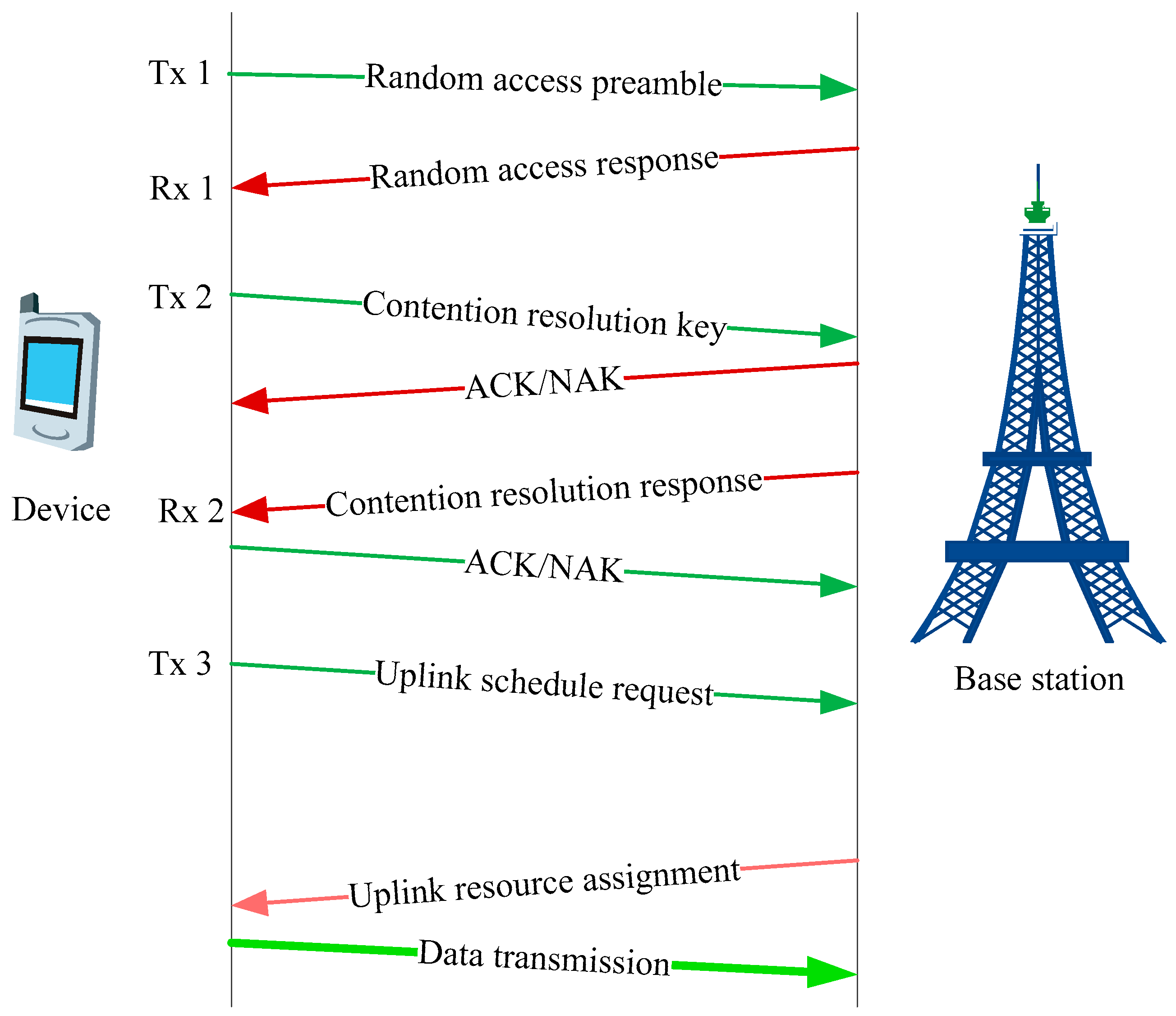
Figure 3 shows the simplified random access procedure for LTE-nMTC.
Although the access message decoding does not require the timing information due to the protection of the long CP in the current design, the round-trip propagation delay of the access signal, Δ t , still remains unknown and needs to be estimated from the detected access request signal by the base station. The estimated delay is then attached to the uplink resource assignment message (cf. Figure 3) so that the device can adjust its transmission time (according to Δ t ) to ensure the time alignment of the subsequent uplink transmissions (including data and control channels) from different devices. A smaller CP can then be used only to accommodate the multipath spread on the traffic channel. The propagation delay estimation using the access request signal is described in Section 3.4.
The probability of an access channel which is selected by more than one device is
p ch = 1 ( N RACH 1 N RACH ) N 1 = 1 ( 1 1 N RACH ) N 1 .
This is the random access channel collision probability. Another collision situation is that more than one device select the same access ID. It can be expressed as
p ID = 1 ( 1 1 N ID ) N 1 ,
where N ID = 2 10 is the size of the access ID pool. Therefore, the total collision probability can be written as
p c = 1 ( 1 p ch ) ( 1 p ID ) .
In general, the number of access channels N RACH = S / s is smaller than the number of total access IDs. Therefore, p c p ch . When an access channel is selected by more than one device, there will be a decoding failure at the base station. The device will prepare another random access attempt when there is no uplink resource assignment to itself in a given duration. Apparently, the collision will increase the air time.
Reducing the collision probability requires an increase in the number of access channels, N RACH . However, for a given total random access bandwidth of W , a larger N RACH means a smaller bandwidth ( w = W / N RACH ) per random access channel, a lower data rate that each channel supports, and a longer transmission time for a device. The following question then arises: Given a bandwidth of W , what is the resource configuration scheme for the random access channels (i.e., the bandwidth of a random access channel) that minimizes the overall access request message transmission time? We use the “effective bandwidth” to solve this question [22].

3.3. Effective Bandwidth and Optimal Resource Configuration

The SNR of an OFDM resource element (RE, i.e., a subcarrier over the duration of an OFDM symbol T ) of the random access channel can be represented as
ρ RE = p T / s α ζ N 0 = 1 s p T α ζ N 0
as a result of matched-filtering via DFT, where T = w 0 1 = ( W / S ) 1 is the length of an OFDM symbol in time domain, N 0 is the noise density, ζ is the noise figure, and α is the coupling loss whose value depends on the MTC coverage class of the device: α = 155, 150, 145, and 140 dB for channel coverage classes 1, 2, 3, and 4, respectively. Apparently, the total number of REs per OFDM symbol is s per channel, yielding the maximum data rate (bits/OFDM symbol) of
r = s log ( 1 + ρ RE ) = s log ( 1 + 1 s p T α ζ N 0 ) ,
or, the maximum data rate in bits/sec of
r = s log ( 1 + 1 s p T α ζ N 0 ) / ( T + T CP ) W s S log ( 1 + ( W s S ) 1 p α ζ N 0 ) = w log ( 1 + w 1 p α ζ N 0 ) .
Taking into account the imperfection of a realistic system, (9) becomes
r ( w , α ) = w log ( 1 + β w 1 p α ζ N 0 ) ,
where β is a scaling factor to reflect the gap between the Shannon capacity and a realistic system. r ( w , α ) is a monotonically increasing function of w . Then the transmission time of the access request message M is given by
τ ( w , α , | M | ) = | M | w log ( 1 + w 1 β p α ζ N 0 ) .
It means the larger the w is, the larger the data rate, and the smaller the transmission time. In fact, when w ,
τ ( , α , | M | ) = lim w τ ( w , α , | M | ) = | M | ln 2 β P α ζ N 0 ,
which represents the minimum transmission time for message M , i.e.,
τ ( w , α , | M | ) > τ ( , α , | M | ) ,   w < .
given α or the coverage class.
Figure 4 plots (11) relative to τ ( , α , | M | ) , i.e.,
Δ τ ( w , α ) = τ ( w , α , | M | ) τ ( , α , | M | ) τ ( , α , | M | ) = τ ( w , α , | M | ) τ ( , α , | M | ) 1
for devices belonging to the four coverage classes, which represents the extra transmission time due to the use of a finite transmission bandwidth w (i.e., w < ). In Figure 4, p = P UL = 20 dBm is the uplink transmit power, ζ = 5 dB, and β = −6 dB.
From Figure 4, we can see that the transmission time is monotonically decreasing with respect to the signal bandwidth as we analyzed before. But the decreasing slope of the transmission time is not linear. There is an effective bandwidth w for every coverage class such that once exceeded, increasing bandwidth has less effect on decreasing the transmission time. If we define w as the effective bandwidth, at which Δ τ ( w , α ) is equal to, e.g., 10%, the w for coverage classes 4, 3, 2, and 1 are then 94, 30, 9, and 3 kHz, respectively. They are summarized in Table 1. The lower the coverage class is, the less sensitive it is to bandwidth. Clearly, devices belonging to the class whose bandwidth is less than the effective bandwidth are therefore bandwidth-limited, and those whose bandwidth is greater than the effective bandwidth are power-limited. The effective bandwidth therefore provides a good balance between the spectral efficiency (or the total number of FDM channels that a given W supports) ant the transmission time. Since the effective bandwidth of a low coverage class is less than that of a high coverage class, more FDM channels are available for a low coverage class for a given total bandwidth.
Based on this effective bandwidth concept, the subcarrier spacing of 15 kHz for legacy LTE data channels is too large for MTC, and a finer granularity is needed. The subcarrier spacing is thus reduced by a factor of 5, i.e., w 0 = 3 kHz in the new design to match the smallest effective bandwidth (CC1). This idea is consistent with the design of NB-IoT design in which 3.75 kHz subcarrier spacing is used [23]. The reduction of subcarrier spacing has the following implications: (1) Five times as many FDM channels for CC1 devices; (2) The OFDM symbol in time domain is elongated by a factor of 5, which boots OFDM symbol energy by 7 dB; and (3) The data channel CP length can also be increased by five times, i.e., 5   μ s × 5 = 25   μ s while maintaining the same CP overhead 25   μ s 25   μ s + ( 3   kHz ) 1 7% as in the legacy LTE, 5   μ s 5   μ s + ( 15   kHz ) 1 7% [24]. Longer CP allows for not only larger multipath spread but also more tolerance to timing errors which relaxes the uplink timing requirement. This is particularly beneficial since timing estimation is less accurate under narrow band than wideband due to the reduced time resolution. However, narrower subcarrier spacing also means more vulnerability to frequency offsets due to frequency tracking errors and/or Doppler spread but it is justified by a much lower mobility (hence lower Doppler effects) in MTC applications than HTC.
Note that τ ( w , α , | M | ) or Δ τ ( w , α ) represents the transmission time for a non-contention based transmission in a collision-free environment as for the data transmissions. But the random access transmission is unscheduled or contentious. The actual transmission time is hence Δ τ ( w , α ) plus the re-transmissions in the case of collisions whose probability is directly related to the number of random access channels, N RACH = W w , as given in (4), and is re-written here,
p c ( w , N ) = 1 ( 1 1 N RACH ) N 1 = 1 ( 1 w W ) N 1 ,  
where N is the number of accessing devices. Therefore, the total transmission time is also a function of the collision probability, and can be derived as follows:
τ c ( w , α , N , | M | ) = lim K i = 1 K ( 1 p c ( w , N ) ) p c i 1 ( w , N ) ( i τ ( w , α , | M | ) ) = τ ( w , α , | M | ) lim K ( 1 p c ( w , N ) ) i = 1 K i p c i 1 ( w , N ) = τ ( w , α , | M | ) lim K ( 1 p c K ( w , N ) 1 p c ( w , N ) K p c K ( w , N ) ) = τ ( w , α , | M | ) lim K 1 p c K ( w , N ) 1 p c ( w , N ) = τ ( w , α , | M | ) 1 p c ( w , N )   .
Clearly, τ c ( w , α , N , | M | ) > τ ( w , α , | M | ) due to the fact that 0 < p c ( w , N ) < 1 in the contention-based random access.
Ultimately, we look for the w that minimizes (16). Alternatively, we search for the w that minimizes the extra time or penalty introduced by the contention among N accessing devices. That is,
w ( α , N ) = arg min w w ( α ) Δ τ c ( w , α , N )   ,
where
Δ τ c ( w , α , N ) = τ c ( w , α , N , | M | ) τ ( w , α , | M | ) 1   .
The optimal random access channel bandwidth in (17) is hence a function of the number of contending devices N per random access opportunity.
Figure plots the time penalty, min w w ( α ) Δ τ c ( w , α , N ) in (17), as a function of N , which is a monotonically increasing function of N , for the four coverage classes. In Figure 5, L i denotes the L for CC i. The transmission power of the device is p = 20 dBm, receiver noise figure ζ = 5 dB, and β = 6 dB. At an, e.g., 10% penalty, the devices that can be supported by W = 180 kHz is N = 7 for CC1 ( α = 155 dB), and 3 for CC2 ( α = 150 dB), whereas for CC3 ( α = 145 dB) and CC4 ( α = 140 dB) N dwindles down to less than two. On the other hand, in order for all high coverage classes to support the same number of devices as CC 1, i.e., N = 7 , they have to live with much higher penalties, i.e., min w w ( α ) Δ τ c ( w ( α , N ) , α , N ) 10 % (for α = 150, 145, and 140 dB).
This phenomenon can be better explained using Figure 6, where we observe that for CC 1 ( α = 155 dB) and at N = 7 , the optimal bandwidth equals the effective bandwidth, i.e., w ( α ) w ( α ) = 1 . The 10% performance penalty is thus purely attributable to collisions. Whereas in order for higher coverage classes to support N = 7 , each random access channel of these classes has to settle with an optimal bandwidth w ( α ) that is much smaller than the effective bandwidth w ( α ) , i.e., w ( α ) w ( α ) 1 ( α = 150, 145, and 140 dB) as shown in Figure 6, in order to make room for a sufficient number of FDM channels, W w . The resultant bandwidth deficit (i.e., w ( α ) w ( α ) < 1 ) gives rise to high performance penalty, i.e., Δ τ c ( w , α , N ) 10 % .
A solution to maintaining the collision at a reasonable low probability (corresponding to, e.g., 10% penalty) for high coverage classes without incurring high bandwidth deficit penalty is to add more random access channels per random access occasion in a time division multiplexing (TDM) fashion so that the total number of random access channels is increased by L times, i.e., N RACH = L W / w , where L is the multiplicity of the TDM random access resources in time domain (cf. Figure 7). The collision probability becomes
p c ( w , N , L ) = 1 ( 1 w L W ) N 1 .
Clearly, (19) is less than (15) for L > 1 . Nevertheless, more TDM resources are needed to compensate for the shortage in bandwidth.
Referring back to Figure 5 (dotted lines), we show the values of L needed for high coverage classes, i.e., L 2 = 3 , L 3 = 12, and L 4 = 36, such that N = 7 can be supported without incurring the bandwidth deficit penalty, i.e., w ( α ) w ( α ) 1 for α = 150, 145, and 140 dB. That is, the penalty due to contention is below 10% as long as the number of concurrent contending devices is less than 7 (cf. Figure 6). In the following discussion, N is hence assumed to be 7 unless otherwise specified. The implication of N on the overall random access capacity will be discussed in Section 4.4.
The optimal channel configurations are summarized in Table 2, whereas Table 3 is for W = 1.08 MHz to show the bandwidth scalability of the design. We observe that the confliction between the channel bandwidth and the total number of channels is less severe under a wider bandwidth ( W = 1.08 MHz), in which less deficit exists between w and w , thereby, less performance loss is attributable to the bandwidth deficit.
Figure 7 is a block diagram illustrating the random access channel configuration for W = 180 kHz, where the number of subcarriers is chosen to be S = 60 which results in a subcarrier spacing of 3 kHz that matches the optimal bandwidth w (cf. Table 2) by design. The CP overhead for an OFDM symbol is 35   μ s 35   μ s + ( 3   kHz ) 1 9%. TTI is the transmission time interval of each random access channel (see Figure 2 and Figure 3), which is related to the link budget of the coverage class, and will be determined in Section 4.

3.4. Physical Layer Mapping and Timing Estimation

As noted before, the use of a preamble is mainly for the purpose of indicating the presence of a device and providing a means for estimate the round-trip propagation delay. The former is achieved by decoding the random access message with the help of CRC check. Then the random access message can be treat as a known signal after successful decoding. So we can use it as the “preamble” to estimate the uplink timing.
According to the analysis in above, we know that the random access signal contains s subcarriers and the optimal s for different coverage classes are different. As we mention before, the timing accuracy is related to the signal bandwidth. We therefore use a hopping pattern to increase the timing accuracy. For the random access signals which contain more than one subcarrier, we can treat them as the combination of several standalone subcarriers. Therefore, we just need to define the subcarrier level hopping pattern.
Figure 8 shows an example of the resource element mapping of our proposed random access signal with one subcarrier (e.g., CC1). In our design, every five OFDM symbols is defined as a symbol group, the middle resource element is the pilot for demodulation and decoding, the rest are used to convey the random access message M . The hopping is done in adjacent symbol groups with the hopping step Δ q subcarriers. In order to take full advantage of resources, we define a bi-direction hopping pattern. That is, for the two subcarriers whose gap is Δ q , their hopping direction is opposite as shown in Figure 8 (the tones with the same color is corresponding to a logic subcarrier of random access signal). Therefore, for the random access signal contains several subcarriers, we can map these subcarriers to several standalone subcarriers in physical resource to further increase the virtual signal bandwidth for timing estimation.
According to our previous work [21], the hopping step Δ q should satisfy
2 π Δ q w 0 Δ t < 2 π ,
where w 0 is the subcarrier spacing, Δ t is the maximum round-trip propagation delay. For example, the maximum value of Δ q is 9 for 35 us propagation delay with the subcarrier spacing 3.75 kHz.

4. Link Budget Analysis and Simulation Results

Simulations have been carried out to examine the performance of LTE-nMTC random access design developed in the previous section, under the typical MTC environment (EPA 1 Hz [25]). The operating bandwidth of an MTC device is 180 kHz, with subcarrier spacing of 3 kHz and a CP length of 35 μ s for random access channels, and 25 μ s for traffic channels. The frequency offset is assumed to be uniformly-distributed in [−50, 50] Hz, and the time offset is assumed to be uniformly-distributed in [0, 35] μ s .

4.1. Link Budget Analysis

Before the simulation, the link budget for each coverage class needs to be analyzed so that the operating SNR for each coverage class can be determined.
The requirement of the receiver sensitivity is p α (dBm). Then, the required received SNR is
Γ = ( p α ) ( w + N 0 + ζ )   ( dB ) .
where w (dB-Hz) is the signal bandwidth, ζ (dB) is the noise figure, N 0 (dBm/Hz) is the noise density.
For the uplink, all the transmitter power P UL can be transmitted on the actual signal operating bandwidth, i.e., p = P UL . Then, the received SNR becomes
Γ UL = ( P UL α ) ( w + N 0 + ζ UL ) .
For LTE-nMTC random access channels, w = w ( α ) , α = 155, 150, 145, and 140 dB.
For the downlink, the transmitter power is evenly distributed to the whole band. The power on bandwidth w is p = P DL + w Π (dBm), where P DL (dBm) is the total transmit power for the entire system bandwidth of Π (dB-Hz). The received SNR becomes
Γ DL = ( P DL Π ) α N 0 ζ DL   ( dB )
Unlike the uplink, the downlink SNR is not a function of the signal bandwidth w .
Taking the uplink as an example, assuming P UL = 20 dBm, the required receiver sensitivity is thus P UL α = 20   dBm α   dB . The typical noise figure of a base station receiver is ζ UL = 5 dB, the received SNR according to (22), is
Γ ( α , w ) = ( 20   dBm α   dB ) ( w   dB Hz + ( 174   dBm / Hz ) + 5   dB ) = 189   dBm ( α + w )   dB .
For the LTE-nMTC access request signal, w = w ( α ) , i.e., coverage class dependent. Referring back to Table 2, α + w ( α ) 189 dB for α = 155, 150, 145, and 140 dB, yielding Γ = 0 dB for all coverage classes. That is, the operating SNRs for the access request signal are the same for all coverage classes as listed in Table 4.
The link budget for the LTE-eMTC random access signals can be analyzed similarly, except that unlike in LTE-nMTC where the signal bandwidth is individually optimized for each coverage class, the channel bandwidth w for LTE-eMTC random access signals are coverage classes independent. The operating SNRs are therefore different for different coverage classes. For the downlink, assuming the transmit power is 46 dBm for 10 MHz bandwidth, and the noise figure is 9 dB. Table 4 shows the corresponding operating SNRs in each random access step.

4.2. Simulation Results

Figure 9 shows the decoding performance of the LTE-nMTC random access request signal for various coverage classes. The transmission time intervals (TTIs) for the LTE-nMTC access request signal to close the various coverage class links are summarized in Table 5 for reference. The TTI is the minimum transmission length determined such that the SNR at 1% packet error rate (PER) is less than Γ . From Table 5, we can see that the preamble transmission time in LTE-eMTC (Tx1) is about one third of our proposed LTE-nMTC random access message design. This is a matter of course that LTE-eMTC preamble only contains partial of the random access message, i.e., the round trip delay and the absence of a device without detail information. In order to deal with the potential collision, the device has to transmit the contention resolution key (Tx2) again after it detects the RAR. Therefore, the transmission time increases and exceeds our proposed design. We can see that the device total transmission time in the LTE-eMTC random access procedure is at least 1.5 times the transmission time of our proposed random access message. Moreover, the random access procedure in LTE-eMTC is divided into four steps, including uplink and downlink, which will increase the access delay comparing to our one-step random access message design.
Let’s consider coverage class 1 as an example. After considering the collision probability
p c = 1 ( 1 w L W ) N 1 = 9.6 %
and decoding error ( p e = 1 % ), the average transmission time for LTE-nMTC can be expressed as
t Tx = T Tx ( 1 p e ) ( 1 p c ) = 0.2578   s ( 1 1 % ) ( 1 9.6 % ) 0.288   s ,
where T Tx is the TTI for LTE-nMTC coverage class 1, and the 9% collision probability is obtained from (15). Hence, total power consumption per random access according to (1) is
C LTE-nMTC = t Tx I Tx = 0.288   s   ×   260   mA 0.021   mAh  
or 0.00042% two AA battery capacity ( C AA =   5000   mAh ).
For LTE-eMTC, it is approximately (ignoring the collision, miss of preamble detection, and random access response and contention resolution decoding error)
C LTE-eMTC = t Tx I Tx + t Rx I Rx = ( T Tx 1 + T Tx 2 + T Tx 3 ) I Tx + ( T Rx 1 + T Rx 2 ) I Rx = ( 0.08 + 0.85 + 0.13 )   s   ×   260   mA + ( 1.564 + 0.574 )   s   ×   150   mA 0.166   mAh
or 0.0033 % two AA battery capacity. This is an 87 % reduction in power consumption for random access.
Figure 10 shows the comparison of power consumption (in terms of two AA batteries) between LTE-nMTC and LTE-eMTC under different coverage classes.
Longer air time not only means higher power consumption, it also means a higher resource overhead. The total time-frequency resources used is 180   kHz × 0.288   s = 51,840 for LTE-nMTC, whereas 1,210,680 for LTE-eMTC. The reduction in resource usage for each random access is therefore around 95.7 % .
Figure 11 shows the uplink timing performance of our proposed random access signal for different coverage classes with operating SNR Γ listed in Table 4. The timing estimation method is according to [21]. In our design, the CP of the OFDM symbol for the traffic/data channels is 25   μ s . It is used to absorb the timing error of random access and the multipath delay spread. We observe that the timing error is in the range of ± 5   μ s (95 percentile) which consumes about 10   μ s of the CP, leaving 15 μ s for the multipath delay spread, which is sufficient for the traffic channels.

4.3. Support for Larger Cells

So far in the discussion, a CP size of 35 μ s (corresponding to typical cell sizes of less than 5 km) is used for the random access channel to absorb the propagation delay. Due to the low duty cycle of the random access (e.g., 10%), the overall overhead of the random access channel CP is rather small even with a much larger CP. Therefore, very large cells can be supported with the current design. For instance, a CP of 235 μ s (for a cell size of 35 km) can be supported corresponding to an overall system overhead of less than 4%.

4.4. Random Access Capacity

From the previous analysis, the number of devices per random access opportunity, N , of the current design for the bandwidth of W = 180 kHz should be controlled below 7. For the random access duration of about 0.25 s, the random access period is set to be 2.5 s to maintain a 10% overall overhead (cf. Figure 7). Therefore, a total of 60   s / 2.5   s × 7 = 168 devices can be supported per minute, per band (of width 180 kHz), and per cell. The random access capacity of a cell is thus 168 devices per band for the device wake up period of 1 min, and 2520, 5040, and 10,080 devices for the periods of 15, 30, and 60 min, respectively. The control mechanism of the number of random access devices per random access occasion can be found in ref. [26].

5. Conclusions

Machine type communication is a key component of Internet of Things for connecting devices. Cellular networks have the greatest potential to provide a reliable and global connectivity for MTC applications. One of the major challenges in cellular MTC is efficient random access, a process via which a device establishes a (wireless) communication link with the network. Its power and spectral efficiency is of particular importance to cellular MTC due to the MTC device’s battery limitation and scarce cellular spectrum. In this paper, we review the random access mechanism in the traditional LTE/LTE-eMTC system and address its limitations when applied to MTC. Firstly, the bandwidth that is used for transmitting the random access preamble signal is fixed at 1.08 MHz, which prevents it from being deployed in a narrower bandwidth such as the 200 kHz re-farmed GSM bands, and hence hinders the application of legacy LTE (and LTE-eMTC) to mass IoT markets due to the already-scarce LTE bands. Secondly, the random access procedure that is optimized for human-type communications presents a significant overhead for machine-type data communications that are typically characterized by infrequent small data bursts. We then present a power- and spectrally-optimized, and bandwidth-scalable random access design, tailored specifically for cellular MTC. Specifically, we utilize a packet-based random access signal. We introduce the concept of effective bandwidth, and use it to optimize the power and spectral efficiency of the random access signal under a contention-based signaling environment. At last, the simulation shows that our proposed random access signal can achieve about 87% reduction in power consumption and 95.7% in resource usage comparing to the LTE/LTE-eMTC random access procedure.
In the future, the number of access devices in the massive IoT scenario will be huge. In general, the random access delay increase along with the devices number increases. Fortunately, only a few of the devices are active at the same time. So one of the key challenges is to determine how to detect the active devices and then decode their data with low latency. Grant-free strategies might be a good solution to simplify the random access procedure and lower the access delay.

Author Contributions

Conceptualization, H.Y.; writing—original draft preparation, H.Y. and J.Z.; writing—review and editing, J.Z. and C.X.; supervision, J.Z.; validation, C.X.

Funding

This research was funded by the National Natural Science Foundation of China (No. 61701234) and the Fundamental Research Funds for the Central Universities (No. 30917011318, No. 30920140122005).

Conflicts of Interest

The authors declare no conflict of interest.

References

  1. Rajpal, J. Framework for enabling machine-type communication services. IET Wirel. Sens. Syst. 2017, 7, 9–14. [Google Scholar] [CrossRef]
  2. Xia, N.; Chen, H.; Yang, C. Radio resource management in Machine-to-Machine communications—A survey. IEEE Commun. Surv. Tutor. 2018, 20, 791–828. [Google Scholar] [CrossRef]
  3. Ali, M.S.; Hossain, E.; Kim, D.I. LTE/LTE-A random access for massive Machine-Type Communications in Smart Cities. IEEE Commun. Mag. 2017, 55, 76–83. [Google Scholar] [CrossRef]
  4. Wu, G.; Talwar, S.; Johnsson, K.; Himayat, N.; Johnson, K.D. M2M: From mobile to embedded Internet. IEEE Commun. Mag. 2011, 49, 36–43. [Google Scholar]
  5. Knight, M. Wireless security—How safe is Z-wave? Comput. Control Eng. J. 2006, 17, 18–23. [Google Scholar] [CrossRef]
  6. SIGFOX Whitepaper. SIGFOX—One Network a Billion Dreams. Available online: https://docslide.us/technology/sigfox-whitepaper.html (accessed on 8 October 2018).
  7. Sornin, N. LoRaWAN Specfication. Available online: https://lora-alliance.org/resource-hub (accessed on 8 October 2018).
  8. Weightless Specfication. Available online: http://www.weightless.org/about/weightless-specification (accessed on 8 October 2018).
  9. Lippuner, S.; Weber, B.; Salomon, M.; Korb, M.; Huang, Q. EC-GSM-IoT network synchronization with support for large frequency offsets. In Proceedings of the 2018 IEEE Wireless Communications and Networking Conference (WCNC), Barcelona, Spain, 15–18 April 2018; pp. 1–6. [Google Scholar]
  10. Hoglund, A. Overview of 3GPP release 14 enhanced NB-IoT. IEEE Netw. 2017, 31, 16–22. [Google Scholar] [CrossRef]
  11. Tsiropoulou, E.E.; Katsinis, G.K.; Vamvakas, P.; Papavassiliou, S. Efficient uplink power control in multi-service two-tier femtocell networks via a game theoretic approach. In Proceedings of the 2013 IEEE 18th International Workshop on Computer Aided Modeling and Design of Communication Links and Networks (CAMAD), Berlin, Germany, 25–27 September 2013; pp. 104–108. [Google Scholar]
  12. Tsiropoulou, E.E.; Katsinis, G.K.; Filios, A.; Papavassiliou, S. On the Problem of Optimal Cell Selection and Uplink Power Control in Open Access Multi-service Two-Tier Femtocell Networks. In Proceedings of the 2014 Ad-Hoc, Mobile, and Wireless Networks (ADHOC-NOW), Benidorm, Spain, 22–27 June 2014; pp. 114–127. [Google Scholar]
  13. Zahir, T.; Arshad, K.; Nakata, A.; Moessner, K. Interference Management in Femtocells. IEEE Commun. Surv. Tutor. 2013, 15, 293–311. [Google Scholar] [CrossRef] [Green Version]
  14. Chandrasekhar, V.; Andrews, J.G.; Muharemovic, T.; Shen, Z.; Gatherer, A. Power control in two-tier femtocell networks. IEEE Trans. Wirel. Commun. 2009, 8, 4316–4328. [Google Scholar] [CrossRef] [Green Version]
  15. Li, L.; Xu, C.; Tao, M. Resource Allocation in Open Access OFDMA Femtocell Networks. IEEE Wirel. Commun. Lett. 2012, 1, 625–628. [Google Scholar] [CrossRef]
  16. 3GPP. Technical Specification Group Services and System Aspects System Improvements for Machine-Type Communications (MTC) (Release 11). TS 23.888, ver.11.0.0. March 2013. Available online: ftp://3gpp.org/Specs/2013-03/Rel-11/23_series/ (accessed on 8 October 2018).
  17. 3GPP. Technical Specification Group Services and System Aspects Service Requirements for Machine-Type Communications (MTC) Stage 1 (Release 13). TR 22.368, ver.13.1.0. December 2014. Available online: ftp://3gpp.org/Specs/2014-12/Rel-13/22_series/ (accessed on 8 October 2018).
  18. 3GPP. Technical Specification Group Radio Access Network Evolved Universal Terrestrial Radio Access (E-UTRA) Physical Channels And Modulation (Release 12). TS 36.211, ver.12.4.0. December 2014. Available online: ftp://3gpp.org/Specs/2014-12/Rel-12/36_series/ (accessed on 8 October 2018).
  19. Balasubramanya, N.M.; Lampe, L.; Vos, G.; Bennett, S. On timing reacquisition and Enhanced Primary Synchronization Signal (ePSS) design for energy efficient 3GPP LTE MTC. IEEE Trans. Mob. Comput. 2017, 16, 2292–2305. [Google Scholar] [CrossRef]
  20. Holma, H.; Toskala, A. WCDMA for UMTS-HSPA Evolution and LTE.; John Wiley & Sons: New York, NY, USA, 2007. [Google Scholar]
  21. Zou, J.; Yu, H.; Miao, W.W.; Jiang, C.L. Packet-Based preamble design for random access in massive IoT communication systems. IEEE Access. 2017, 5, 11759–11767. [Google Scholar] [CrossRef]
  22. Yang, W.; Wang, M.; Zhang, J.; Zou, J.; Hua, M.; Xia, T.; You, X. Narrowband wireless access for low-power massive Internet of Things: A bandwidth perspective. IEEE Wirel. Commun. Mag. 2017, 99, 2–9. [Google Scholar] [CrossRef]
  23. 3GPP. Technical specification group radio access network Evolved Universal Terrestrial Radio Access (E-UTRA) physical channels and modulation (Release 14). TS 36.211, ver.14.4.0. September 2017. Available online: ftp://3gpp.org/Specs/2017-09/Rel-14/36_series/ (accessed on 8 October 2018).
  24. Tarik, T.; Andreas, K. Machine type communications in 3GPP networks potential, challenges, and solutions. IEEE Commun. Mag. 2012, 50, 178–184. [Google Scholar]
  25. 3GPP. Technical Specification Group Radio Access Network Study on Provision of Low-Cost Machine-Type Communications (MTC) User Equipment (Device) Based on LTE (Release 12). TR 36.888, ver.12.0.0. June 2013. Available online: ftp://3gpp.org/Specs/2013-06/Rel-12/36_series/ (accessed on 8 October 2018).
  26. Duan, S.; Shah-Mansouri, V.; Wang, Z.; Wong, V.W. D-ACB: Adaptive congestion control algorithm for bursty M2M traffic in LTE networks. IEEE Trans. Veh. Technol. 2016, 65, 9847–9861. [Google Scholar] [CrossRef]
Figure 1. Illustration of random access procedure in LTE/LTE-eMTC.
Electronics 07 00286 g001
Figure 2. Illustration of the proposed random access signal and the corresponding arrive time.
Electronics 07 00286 g002
Figure 3. Illustration of the simplified random access signaling and uplink data transmission.
Electronics 07 00286 g003
Figure 4. The relationship between the transmission bandwidth and transmission time.
Electronics 07 00286 g004
Figure 5. Plot of min w w Δ τ c ( w , α , N ) in (17) as a function of the number of contending devices.
Electronics 07 00286 g005
Figure 6. Relative transmit time in (18) for the access request message with W = 180 kHz.
Electronics 07 00286 g006
Figure 7. Illustrative diagram of the resource configurations for random access channels (RACHs).
Electronics 07 00286 g007
Figure 8. Illustration of access request signal hopping for time offset estimation.
Electronics 07 00286 g008
Figure 9. PER (packet error rate) of LTE-nMTC random access under different coverage classes.
Electronics 07 00286 g009
Figure 10. Power consumption of LTE-nMTC random access and LTE-eMTC random access.
Electronics 07 00286 g010
Figure 11. Timing estimation performance of LTE-nMTC random access signal.
Electronics 07 00286 g011
Table 1. Effective bandwidth for different coverage classes [according to (14)].
Coverage   Class   α 4 (140 dB)3 (145 dB)2 (150 dB)1 (155 dB)
Effective bandwidth w ( α ) (kHz)943093
Extra transmission time Δ τ ( w , α ) (%)10
Table 2. Random access channel configuration for the total bandwidth of 180 kHz according (17).
Coverage   Class   α 4 (140 dB)3 (145 dB)2 (150 dB)1 (155 dB)
TDM channels L 136112131
Optimal bandwidth w (kHz)1290930693
Channel bandwidth w (kHz)1290930693
Number of subcarriers per channel s 430310231
Total channels N RACH = L W / w = L S / s 15722072306060
Time penalty Δ τ c ( w , α ) (%)1309609271110
Table 3. Random access channel configuration for the total bandwidth of 1.08 MHz according (17).
Coverage   class   α 4 (140 dB)3 (145 dB)2 (150 dB)1 (155 dB)
TDM channels L 136112131
Optimal bandwidth w (kHz)1290930693
Channel bandwidth w (kHz)1290930693
Number of subcarriers per channel s 430310231
Total channels N RACH = L W / w = L S / s 90432120432180360360
Time penalty Δ τ c ( w , α ) (%)1259598261010
Table 4. Random access channel operating SNRs under the LTE-nMTC design and LTE-eMTC.
Coverage   Class   ( α ) 4 (140 dB)3 (145 dB)2 (150 dB)1 (155 dB)
Γ (dB)LTE-nMTCTx10000
LTE-eMTCTx 1−11−16−21−26
Tx (2, 3)−4−9−14−19
Rx (1, 2)1−4−9−14
Table 5. Transmission time intervals of LTE-nMTC and LTE-eMTC random access message.
Coverage   Class   ( α ) 4 (140 dB)3 (145 dB)2 (150 dB)1 (155 dB)
TTI (sec)LTE-nMTCTx10.0074
(5 symbol groups)
0.0221
(12 symbol groups)
0.09945
(54 symbol groups)
0.2578
(140 symbol groups)
LTE-eMTCTx10.0020.0070.030.08
Rx10.1160.2740.6381.564
Tx20.0080.0450.20.85
Rx20.0110.0340.1380.574
Tx30.0010.0080.060.13

