1. Introduction
With the rapidly advancing technology, unmanned aerial vehicles (UAVs), widely known as drones, are becoming increasingly effective and significantly less costly during recent years. These vehicles can be controlled either under remote control (RC) by a pilot operator or autonomously by onboard computers. A UAV communication channel is a key factor that can affect the performance of the data link in terms of high data rate and reliable transmission of information. In other words, ensuring the efficiency of a UAV communication link represents one of the great challenges of the current works regarding a UAV communication system.
The UAV communication system has the following major requirements:
As the transmission of control commands and gathered data, which can be recorded video and photos, is achieved through the communication channel between the UAV and the ground control station (GCS), a UAV data link requires the highest reliability in data transmission as well as a high data transfer rate. Nowadays, in order to provide an efficient communication link, many drones use the spread spectrum technology that allows many different pilots to operate in the same 2.4 GHz band without conflicts. Receivers in this band are virtually immune against interference issues.
Essentially, two types of spread spectrum technology are used for the UAV communication link. The first one is the frequency-hopping spread spectrum (FHSS), which unceasingly changes its narrowband frequency on several occasions a second within the 2.4 GHz frequency range. In this process, the receiver recognizes the patterns of frequency that are utilized by a transmitter. Because the transmitter changes frequency from one to another, the receiver can adopt a suitable frequency. Unlike FHSS, a direct-sequence spread spectrum (DSSS) system uses a much wider bandwidth to transmit the signal on a single selected frequency. The transmitter sends an original narrowband signal via a spreading code generator that multiplies the narrowband data signal using a much higher frequency. Anyway, both spread spectrum modes (FHSS and DSSS) transmit the signal within the 2.4 GHz frequency band. In practice, orthogonal frequency division multiplexing (OFDM) modulation has been considered more efficient than FHSS and DSSS due to its greater tolerance of multipath distortion, higher throughput, and potential data rate [
1].
Nowadays, the demand on the long-range operation and long flight time is increasing in UAV communication systems and the currently used modulation techniques have the fundamental constraint to meet this demand. Therefore, we need to adopt a potential modulation technique that fulfills this demand. In fact, it is essential to adopt the most effective technique that can provide a highly efficient data link between the vehicle and GCS. The main contribution of this paper is the investigation of the SC-FDM modulation technique in a UAV communication system in order to provide an efficient UAV communication link and extend the flight time (battery life) of drones. The performance of the adopted modulation technique is analyzed by comparing it with the OFDM modulation. Additionally, SC-FDM has been considered to transfer the data using different kinds of modulation schemes such as M-ary phase-shift keying (BPSK, QPSK, and 8-PSK) and M-ary quadrature amplitude modulation (16-QAM and 64-QAM) in this work.
The remaining part of our paper is structured as follows. In
Section 2, some related works are discussed.
Section 3 demonstrates the UAV communication link and communication system components. The comparison between the proposed modulation technique and the OFDM modulation is presented in
Section 4. We show the experimental setup and performance measures of the system in
Section 5. Afterwards,
Section 6 illustrates the comparative results obtained from experiments. At the end of the paper,
Section 7 presents our conclusions and future work.
2. Related Works
In recent years, extending the battery life and flight time of quadcopters has become a crucial task, since most of these vehicles are used for delivery services and military tasks. To maintain flight time, quadcopter power modeling is a basic technology because the limitation of the flight time actually comes from the battery capacity constraint. Maekawa et al. [
2] proposed a simple model of power consumption for delivery quadcopters by testing the Parrot AR. Drone 2.0 on a horizontal flight. The power consumption of the drone was measured by a current logger and light weighted voltage. However, their proposed power model is based only on average power consumption data obtained during the horizontal flight. The work by Sowah et al. [
3] presents a rotational energy harvester powered by rotors using a brushless dc (BLDC) generator to increase the flight time of quadcopters. A printed circuit board (PCB) and Eagle PCB design software (EAGLE 6.4.0 Light) were used to build the physical model. The harvester interface circuit consumed 1.5 to 3.2 V as an input from the rectifier circuit and produced an adjustable output of 18 V with 2.7 W output power for each generator at 82% efficiency. A 600 mA of current from the four generators was utilized to provide extra flight time for the quadcopter, thus, gaining about 42% in flight duration. Moreover, in [
4], a comparison of BLDC control and field-oriented control (FOC) techniques has been analyzed in order to enhance the flight endurance of multirotor UAVs. According to the power efficiency and output torque quality of propeller electrical drives, FOC has shown better performance by 2–4% in efficiency compared to BLDC control, leading to flight endurance improvement.
A method for improving the efficiency of the UAV communication link can be found in [
5]. In this work, the key tasks of a UAV communication system and characteristics of a radio channel between the UAV and ground control unit (GCU) have been analyzed. Considering the various issues associated with a UAV communication link, an author proposed the optimal radio channel construction using the rotary and mounting platform with antennas, power and low-noise amplifiers as well as an OFDM modulation technique to increase the data transfer rate. In [
6], Wu et al. proposed OFDM as a transmission system for UAV wireless communications. Initially, to find out the proper OFDM system parameters, the coherence time and Doppler spread have been measured. After obtaining the inter-carrier interference (ICI) coefficients, they evaluated the bit error rate (BER) performance of OFDM technology in a typical UAV communication channel and these performance results were compared with those of OFDM in normal wireless indoor channels. According to their simulation results, an insignificant performance degradation can be seen when the OFDM technology is applied to the UAV communication channel.
In UAV applications, there have been few efforts to adopt the SC-FDM modulation technology for a UAV communication system, while it has been widely accepted in mobile communications. In [
7], Miko and Nemeth proposed a hardware architecture which includes a Xilinx field-programmable gate array (FPGA) combined with the software-defined radio (SDR) chip and SC-FDM modulation system to provide a high data transmission rate and radio navigation for the communication link of UAV systems. Their proposed hardware design of the transceiver is shown in
Figure 1. They implemented modulation, demodulation, and coding functions in the FPGA. However, there is no indication of the performance of SC-FDM modulation in their work.
Until now, most of the previous works on the single-carrier frequency division multiple access (SC-FDMA) have been carried out for uplink communications in the long-term evolution (LTE) technology of mobile communication systems [
8,
9,
10,
11,
12,
13]. As an alternative to the orthogonal frequency division multiple access (OFDMA), SC-FDMA has drawn considerable attention in mobile communications. In [
14], Myung gives an overview of SC-FDMA. Another research focuses on PAPR reduction of localized SC-FDMA using a partial transmit sequence (PTS) [
15]. Actually, there can be localized and distributed modes of subcarrier mapping in SC-FDMA [
14,
16]. In localized SC-FDMA, each terminal uses a set of contiguous subcarriers for the transmission of symbols, thereby limiting them to only a portion of the system bandwidth. On the other hand, the subcarriers used by the terminal are propagated throughout the entire bandwidth in the distributed SC-FDMA. Localized SC-FDMA, which is used for uplink transmission of LTE systems, has lower PAPR than distributed SC-FDMA.
Furthermore, Tsiropoulou et al. [
17] provided a bargaining model and power optimization framework to solve the problem of subcarrier and power allocation in multiuser SC-FDMA wireless networks. The obtained numerical results and key features of their proposed approach demonstrate that the introduced framework can be a foundation for the supporting heterogeneous services and the implementation of different users’ priorities to access the available resources. Towards this direction, a similar work can be found in [
18]. In 2016, Tsiropoulou et al. [
19] studied and examined the various state-of-the-art resource allocation algorithms and frameworks developed to allocate the subcarriers and transmission power of users in the uplink of SC-FDMA wireless networks. Luo and Xiong [
20] proposed the SC-FDMA-IDMA system model, which is the combination of SC-FDMA and interleaved division multiple access (IDMA) and studied the effect of carrier frequency offset (CFO) on the BER performance of this system model.
3. UAV Communication System
In general, a UAV communication link can both send control commands from the GCS to the vehicle and receive data about the flight on downlink, as shown in
Figure 2. A bidirectional link can be established in order to provide a communication between the drone and GCS [
21]. A communication link between these two components has to provide long-range operations as well as a continuous and stable link. Therefore, the establishment of a channel model that is suitable for UAV characteristics plays an important role in improving the data link of the UAV [
22,
23]. Furthermore, for improving reliability of the data link, an adaptive information rate method is presented in [
24].
Figure 3 illustrates the components of the UAV communication system. The main component is the microcontroller, also referred to as a flight controller, which is the core for all functioning of a UAV. It manages failsafe, autopilot, waypoints, and many other autonomous functions. This microcontroller interprets input from the receiver, global positioning system (GPS) module, battery monitor, inertial measurement unit (IMU) that include an accelerometer and a gyroscope which can be used for providing stability or maintain a reference direction in navigation system [
25], and other onboard sensors. The GCS provides relevant data about the vehicle such as speed, attitude, altitude, location, yaw, pitch, roll, warnings, and other information [
26]. As shown in
Figure 3, a UAV has two links: data link and communication link. To ensure the transmission of data between the vehicle and GCS, a UAV uses a data link that operates in the frequency range from 150 MHz to 1.5 GHz. On the other hand, a 2.4 GHz frequency band that determines the communication link between the transmitter and receiver is used in order to control the vehicle. It should be noted that the transmitter and receiver must both be on the same frequency. In point of fact, drones have exclusive use of their own frequency allocation due to the longer range and potentially worse consequences of radio interference. Initially, drones scan the range of frequencies within the 2.4 GHz band and use only the narrowband frequency that is not in use by another drone. As a result of this, many drones can utilize a 2.4 GHz frequency band simultaneously. This feature of drones can be noticeable when a number of drones are used as flying base stations in wireless cellular networks to serve an arbitrarily located set of users [
27,
28,
29]. Moreover, typical UAVs use multiple radio interfaces to maintain a continuous connection with essential links to GCSs, other UAVs, and satellite relays.
The modulation and demodulation process of a transmitted signal through a wireless channel can respectively be done in the transmitter and receiver of the UAV communication system.
Figure 4 shows the typical transmitter of a UAV communication system that transmits the control commands and telemetry data. Initially, the input data is stored in a data storage module, then, the channel coding can be used for error correction encoding. After that, the data streams are mapped into the frames and ready for channel modulation. The baseband modulation of each carrier can be selected among BPSK, QPSK, 8-PSK, 16-QAM, and 64-QAM depending on the channel condition. The modulated signals are then directly converted into the radio frequency band for wireless transmission. Before transmitting a signal, the radio frequency (RF) amplifier can be used to convert a low-power frequency signal into a higher one. Finally, the RF signal transmission is done at the transmitter antenna.
4. The Proposed SC-FDM and OFDM
In general, SC-FDM behaves like a single-carrier system with a short symbol duration compared to OFDM. To achieve this, SC-FDM introduces an N-point discrete Fourier transform (DFT) block right after the serial to parallel converter in the OFDM structure. The DFT block converts parallel sequences of symbols in the time domain to different frequency points. The major disadvantage of the OFDM is its high PAPR. This is a consequence of the fact that the transferred signal is the amount of all the modulated subcarriers and some of them are in a phase with high amplitudes that cannot be avoided [
30]. Due to this reason, the power structure of the transmitter is characterized by relatively low average- and high-power peaks. SC-FDM allows a symbol to be transmitted in parts over multiple subcarriers, but in OFDM, we have one to one mapping between symbol and subcarrier. For example, in OFDM one symbol occupies one subcarrier of 15 kHz, but in SC-FDM, the same symbol is distributed among multiple subcarriers of 15 kHz, as described in
Figure 5 [
31].
4.1. OFDM
In
Figure 5, shown above, the data can be transferred by parallel subcarriers of 15 kHz in OFDM. On the time axis, the further divided subcarriers represent blocks of one symbol duration. This basic unit is known as a resource element, and one symbol is carried by one resource element. In addition, a number of resource elements are used to make a resource block that is the basic unit of scheduling. At the beginning of the modulation process, the data is modulated by a particular modulation scheme in order to transfer the data over these resource elements. This modulation scheme depends on the physical channels mapped on the resource grid. Then, M-point inverse discrete Fourier transform (IDFT) transforms the signals of the parallel frequency domain into samples of a composite time domain signal, which are much easier to generate at the transmitter side. All we need to do is to send these time domain samples at radio frequencies. In wireless channels, due to multipath propagation, there can be delay spread and intersymbol interference (ISI) [
32]. This interference may cause a given transmitted symbol to be distorted by other transmitted symbols. Since OFDM uses composite IDFT samples, a cyclic prefix is added by taking some samples from the end of a symbol period and placing them at the beginning. It provides orthogonality between the subcarriers by keeping the OFDM symbol periodic in the duration of the extended symbol and for that reason, avoiding intercarrier and interchannel interference simultaneously. In the next step, a sampled signal is converted into an analog wave by a digital to analog converter (DAC). A further composite waveform is modulated at the desired RF for transmission. The noticeable advantage of OFDM over SC-FDM is that the frequency domain representation of signals simplifies the signal error correction at the receiver [
33].
4.2. SC-FDM
SC-FDM is a hybrid modulation technique that combines the frequency allocation flexibility and multipath resistance of OFDM and other important characteristics of a single-carrier system. The crucial characteristic of the SC-FDM signal generation is that the PAPR of finite frequency shifted signal ends up being the same as that of the original modulating data symbols and this is very different from that of OFDM for the same occupied bandwidth in the same data rate. However, if the channel bandwidth is wider, the link between the symbol length and channel bandwidth can be considered as the disadvantage of SC-FDM in comparison with OFDM [
33].
Figure 6 presents the block diagram for a signal processing chain of SC-FDM. The first step is the same as for OFDM, modulating the data with one of the modulation schemes for data transmission over the resource elements. The data is placed over the resource elements by adjusting the phase and amplitude of the subcarrier to those derived for the data stream. Mathematically, it means multiplying the complex modulation symbol to the corresponding subcarrier frequency. After this process, there is another block in the signal processing chain. To convert the data symbols from the time domain into the frequency domain, the DFT is performed after the serial to parallel conversion. As an OFDM, afterwards, there is subcarrier mapping and an IDFT to transform the signal in the frequency domain into the time domain signal. The cyclic prefix can be inserted when the parallel to serial conversion is done. Before modulating the signal with a high frequency, a pulse shaping filter can be used to get the desired spectrum [
34]. The original values of the symbols can be completely recovered if the transmitted signal is properly sampled at the receiver. The last two steps are the same as for OFDM. Thus, there is no difference in the downlink signal generation chain. In the same way, the reverse of what was done at the transmitter can be accomplished at the receiver. As mentioned in
Section 4.1, each subcarrier carries only one particular modulation symbol in OFDM, while the DFT takes a symbol and spreads it via an available subcarrier in SC-FDM. For that reason, SC-FDM is also referred to as DFT-spread OFDM [
35]. Since the PAPR is proportional to the square of the number of subcarriers involved, SC-FDM reduces the PAPR by reducing the number of subcarriers.
5. Experiments and Performance Measures
5.1. Experiments
In general, our work is divided into two parts. In the first part of our research, we have performed the experimental setup by using the ArduPilot Mega (APM) 2.8 microcontroller and Mission Planner, which is the suitable GCS application for this microcontroller. The APM 2.8 microcontroller uses the micro air vehicle link (MAVLink) protocol [
36] to maintain a connection between the APM 2.8 and GCS. During our experiments, the APM 2.8 board was tested instead of drone in order to obtain the flight data that were used to analyze the SC-FDM modulation for a UAV communication system. As we mentioned in
Section 3, the UAV has a data link that utilizes the frequency range from 150 MHz to 1.5 GHz. In our work, two 3DR 915 MHz telemetry radios were used to provide this data link. To set up a connection between the APM 2.8 and Mission Planner GCS, one of the 3DR 915 MHz telemetry radios was plugged into the APM 2.8, as shown in
Figure 7, while a second telemetry radio was connected to a PC using a USB cable. Since we have the communication link between two telemetry radios, we can check the link status in terms of the number of transmitted packets, frequency range, number of channels, and
power, as shown in
Figure 8a. We configured the connection settings using Mission Planner. After establishing a successful connection, the telemetry data were obtained from the GCS. It should be noted that these data can be represented as signals when they are carried by the MAVLink through a wireless link between the APM 2.8 and GCS. All relevant information about APM 2.8 such as altitude, yaw, pitch, roll, attitude, vertical speed, ground speed, etc., are shown in the “Flight Data” screen of the Mission Planner, see
Figure 8b. When we move the APM 2.8 microcontroller from one place to another, the “Flight Data” screen will display the telemetry data according to the new position of APM 2.8. Afterwards, the telemetry data collected from the GCS were imported into the MATLAB for the modulation process.
In the second part of our work, we have used the data that were gathered from the GCS and static simulation parameters shown in
Table 1 for the modulation process. For this part, MATLAB was used to perform the modulation process.
5.2. Performance Measures
The input data symbols
for
are modulated by one of the modulation schemes using an N-point DFT to generate a representation of the frequency domain of the input symbols and then, the SC-FDM output sequence
for
is given by:
The SC-FDM symbol
is a complex number that consists of real and imaginary parts. According to the central limit theorem, as the number of subcarriers
gets larger, the real and imaginary parts of the SC-FDM symbols follow the normal (Gaussian) distribution and the probability density function (PDF) of
can be shown as [
30]:
where
σ is the standard deviation.
5.2.1. PAPR
One of the key parameters for analyzing the performance of the transferred signal is its peak-to-average power ratio (PAPR), which indicates how extreme the peaks are in a waveform. This can be determined as the ratio of peak power to the average power of the transmitted signal [
37]. In a multicarrier system, PAPR occurs when the different subcarriers do not correspond to a phase with each other at each point. It means that these subcarriers are different relative to each other for different phase values. The value of PAPR depends on the number of subcarriers involved as well as on the modulation scheme. It should be mentioned that high PAPR requires a high power consumption for transmitting a signal. In other words, it can be said that the efficiency of the power amplifier will be very low. On the other hand, a lower value of PAPR results in an increase in the flight time (battery life) of the vehicle. The PAPR of the transmitted signal is defined in the units of dB and it can be expressed as follows:
where
is the maximum value and
is the mean square value of the signal. Here, PAPR is equivalent to the crest factor, as it is defined in decibels. Now, if we consider that
denotes the crest factor, it can be written by:
The cumulative distribution function (CDF) of
is the probability that
will take a value less than or equal to
. The CDF of
is described by [
38]:
Since we have the Equations (5) and (6), we can characterize the PAPR by using a complementary cumulative distribution function (CCDF). The CCDF of the PAPR is the probability of the PAPR which is higher than a certain PAPR value and it can be calculated as:
5.2.2. BER
Another important parameter for measuring the performance of a wireless channel of a UAV communication system is the bit error rate (BER). When data is transmitted over a wireless link between the vehicle and GCS, the BER specifies the number of errors that appear in the received data. The environmental conditions and changes to the propagation path are the fundamental reasons for the communication channel degradation and the respective BER. To achieve an acceptable BER, i.e., for the transmission of control commands on the uplink, a typically acceptable BER is around 10
−6–10
−9, while that acceptable value for the transmission of the payload data on the downlink is 10
−3–10
−4 [
39]. All the available factors must be balanced. Usually, it is difficult to achieve all the requirements and some compromises are required. Moreover, a higher level of error correction is needed in order to recover the original data. This can help to fix the effects of any occurred bit error. It results in the fact that the overall BER can be improved. If the bidirectional communication between the transmitter and receiver is established very well and the signal-to-noise ratio (SNR) is high, then the BER will be potentially insignificant and will not have an observable effect on the whole UAV communication system. The BER is equal to the number of bit errors (
) divided by the total number of transmitted bits (
), as expressed by the following equation:
The
can be computed by comparing the transmitted signal with the received signal. The BER is most often expressed in terms of SNR. The SNR can be defined as the ratio of bit energy (
) to the noise power spectral density (
), which is a power per Hz and it is expressed as follows:
where
is a measure of energy and can be defined by dividing the carrier power by the bit rate.
The probability of bit error (
) represents the probability that the error rate arises in the received signal. The
for M-ary PSK can be defined as:
where
is the average energy of transmitted symbol.
represents the scaled form of the complementary error function (erfc) and it is given by:
It is necessary to note that each different kind of modulation scheme has its own value for the error function. This is due to the fact that each type of modulation scheme executes in different ways in the presence of noise.
Finally, we can calculate the
for M-ary QAM by using the following equation:
5.2.3. Pulse Shaping
The pulse shaping can be used to make the transmitted signal more suitable for the communication channel. In general, pulse shaping is important to ensure the correspondence of a signal in its frequency band. In this paper, a raised-cosine (RC) and root raised-cosine (RRC) pulse shaping filters are used to get the desired spectrum.
To perform the frequency response of the RC filter, we use the following equation:
where
is the frequency,
is the symbol period, and
is the roll-off factor and its value can be between 0 and 1. The representation of the time domain of this filter is given by:
where
is the time. Equations (13) and (14) are used to realize the frequency and impulse responses of the RC filter. Then, the frequency domain transfer function of the RRC filter can be written as:
The impulse response of the RRC filter is given by:
Finally, the performance of each modulation scheme for SC-FDM and OFDM can be measured by calculating the different values of the above-mentioned parameters. To achieve the comparative results that are presented in the following section, the simulation parameters and the data that were collected from the GCS were utilized as the inputs of the system performed with MATLAB.
6. Results Analysis
In this research, MATLAB was used to perform the PAPR simulations of SC-FDM and OFDM as well as the probability of bit error simulation for SC-FDM using different kinds of modulation schemes such as BPSK, QPSK, 8-PSK, 16-QAM, and 64-QAM. Of course, it is essential to select the optimal number of subcarriers, types of the pulse shaping filters and channel equalization when simulation parameters are inputted. The number of subcarriers and symbols depends on the cyclic prefix and the subcarrier spacing. When RC and RRC pulse-shaping filters are used to filter a symbol stream, they can minimize an ISI. Half of this filtering can be done on the transmitter and the second half can be done on the receiver.
The impulse and frequency responses of the RC filter based on different roll-off factors have been plotted and shown in
Figure 9. Furthermore, the equalizer can be used to get the recovery of the transmit symbols by reducing an ISI. By removing all ISI, the zero forcing equalizer can be the optimal choice in the noiseless channel. On the other hand, when a channel is noisy, this equalizer significantly amplifies the noise at frequencies. In this case, the minimum mean square error (MMSE) equalizer can be more efficient than zero forcing. The main function of an MMSE equalizer is minimizing the ISI components and the entire power of the noise in the output instead of eliminating ISI completely.
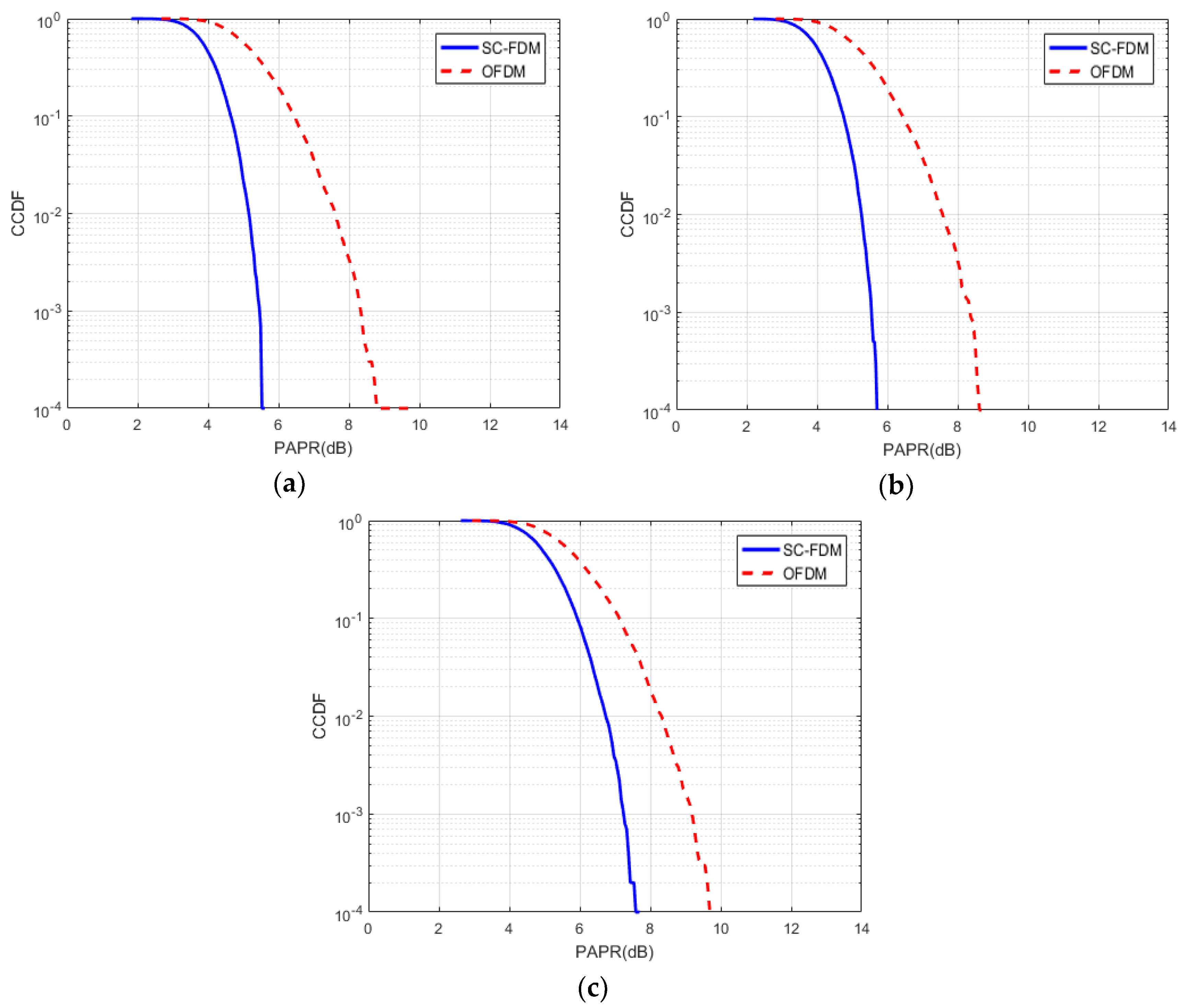
Figure 10 and
Figure 11 plot the peak-to-average power ratio (PAPR) measurements of SC-FDM and OFDM against the complementary cumulative distribution function (CCDF). According to the simulation results, which are shown in
Figure 10 and
Figure 11, the SC-FDM has an advantage over OFDM because of its lower PAPR that leads to an increase in battery performance for a UAV. As shown in
Figure 10a,b, it can be seen that the PAPR value of SC-FDM for a BPSK modulation scheme (5.6 dB) is almost the same as that for QPSK (5.7 dB) when the CCDF is 10
−4. At the same point, the PAPR value of OFDM for BPSK is 8.8 dB and, for QPSK, it equals 8.6 dB. In addition, the simulation results show that 8-PSK has a slightly lower PAPR value than 16-QAM for both SC-FDM and OFDM. From
Figure 11, it can be observed that increasing the order of QAM modulation scheme (16-QAM and 64-QAM) results in increasing the PAPR values of SC-FDM and OFDM from 8 dB and 10 dB to 10 dB and 12.2 dB, respectively. From
Figure 10 and
Figure 11, we can conclude that the abrupt change in the CCDF value comes from the fact that PAPR values are expressed in logarithmic scale for both SC-FDM and OFDM modulation techniques. The PAPR values of SC-FDM and OFDM for different modulation schemes are presented in
Table 2.
The probability of bit error of different modulation schemes for SC-FDM is shown in
Figure 12. From this figure, we can observe that the BPSK and QPSK modulation schemes achieve better performances than other modulation schemes. It is evident that BPSK and QPSK modulation schemes are very suitable for the SC-FDM modulation technique, according to their PAPR and the probability of bit error performances, see
Table 2 and
Figure 12.
In our work, in order to evaluate the complexity of the proposed framework in terms of computation time, we used a computer with an Intel(R) Core(TM) i7-4790 CPU 3.60 GHz; RAM: 16.0 GB; Operating System: Windows 8.1 Pro 64-bit and MATLAB R2016a. As demonstrated in
Figure 13, the computation time of SC-FDM and OFDM modulation techniques depends on the number of subcarriers.
In
Table 3, we have shown the computation time of SC-FDM and OFDM modulation techniques. The computation time of SC-FDM ranged from 222 to 6653 ms with
[256, 4096], while the range for OFDM was between 350 and 9723 ms. We can conclude that the computation time of SC-FDM is lower than that of OFDM.
7. Conclusions
In this paper, we have analyzed the SC-FDM modulation technique in order to provide an efficient communication link between the vehicle and GCS, since the communication link is an essential part of the UAV. The main purpose of this work was to analyze the SC-FDM modulation technique by comparing it with the OFDM. In general, this paper is divided into two parts. In the first part, a UAV communication link, UAV communication system components, as well as some related works have been discussed. On the other hand, the second part provided a brief overview of SC-FDM and OFDM modulation techniques and discussed the simulation results obtained by using various types of modulation schemes such as BPSK, QPSK, 8-PSK, 16-QAM, and 64-QAM. The comparative results show that SC-FDM is more effective than OFDM for the UAV communication system, leading to a noticeable improvement in terms of efficiency of the UAV communication link and the flight time of quadcopters. Moreover, by analyzing the results of our work, we have found that BPSK and QPSK are optimal modulation schemes for the SC-FDM modulation technique.
Due to the fact that the currently used 2.4 GHz band for UAV communication link is utilized by many different communication systems leading to the generation of interferences, some drones have already been designed to operate in the 5.8 GHz band. Thus, our further research will focus on analyzing the 5.8 GHz band for a UAV communication system.
Author Contributions
Conceptualization, S.A. and S.-H.L.; Software, S.A.; Formal Analysis, S.-H.L. and O.-H.K.; Writing-Review & Editing, S.A. and O.-H.K.; Project Administration and Funding Acquisition, K.-R.K.
Funding
This research was supported by the MSIT (Ministry of Science and ICT), Korea, under the Grand Information Technology Research Center support program (IITP-2018-2016-0-00318) supervised by the IITP (Institute for Information & communications Technology Promotion), Basic Science Research Program through the National Research Foundation of Korea (NRF) funded by the Ministry of Science and ICT (No. 2016R1D1A3B03931003, No. 2017R1A2B2012456) and the Korea Technology and Information Promotion Agency for SMEs (TIPA) grant funded by the Korea government (Ministry of SMEs and Startups) (No. C0407372).
Acknowledgments
The authors would like to thank the editors and the reviewers for their valuable time and constructive comments.
Conflicts of Interest
The authors declare no conflict of interest.
References
- Ehichioya, D.; Golriz, A. Performance comparison of OFDM and DSSS on aeronautical channels. In Proceedings of the 45th International Telemetering Conference, Las Vegas, Nevada, USA, 26–29 October 2009. [Google Scholar]
- Maekawa, K.; Negoro, S.; Taniguchi, I.; Tomiyama, H. Power measurement and modeling of quadcopters on horizontal flight. In Proceedings of the 5th International Symposium on Computing and Networking (CANDAR 2017), Aomori, Japan, 19–22 November 2017. [Google Scholar]
- Sowah, R.A.; Acquah, M.A.; Ofoli, A.R.; Mills, G.A.; Koumadi, K.M. Rotational energy harvesting to prolong flight duration of quadcopters. IEEE Trans. Ind. Appl. 2017, 53, 4965–4972. [Google Scholar] [CrossRef]
- Bosso, A.; Conficoni, C.; Tilli, A. Multirotor UAV flight endurance and control: The drive perspective. In Proceedings of the 42nd Annual Conference of the IEEE Industrial Electronics Society (IECON 2016), Florence, Italy, 23–26 October 2016; pp. 1839–1845. [Google Scholar]
- Kuzmenko, A.O. Optimal choice of technical means of UAV communication link. In Proceedings of the IEEE 3rd International Conference on Actual Problems of Unmanned Aerial Vehicles Developments (APUAVD 2015), Kyiv, Ukraine, 13–15 October 2015; pp. 149–152. [Google Scholar]
- Wu, Z.; Kumar, H.; Davari, A. Performance evaluation of OFDM transmission in UAV wireless communication. In Proceedings of the 37th Southeastern Symposium on System Theory (SSST 2005), Tuskegee, AL, USA, 20–22 March 2005; pp. 6–10. [Google Scholar]
- Miko, G.; Nemeth, A. SCFDM based communication system for UAV applications. In Proceedings of the 25th International Conference Radioelektronika, Pardubice, Czech Republic, 21–22 April 2015; pp. 222–224. [Google Scholar]
- Myung, H.G.; Lim, J.; Goodman, D.J. Single carrier FDMA for uplink wireless transmission. IEEE Veh. Technol. Mag. 2006, 1, 30–38. [Google Scholar] [CrossRef]
- Lande, S.B.; Gawali, J.D.; Kharad, S.M. Performance evolution of SC-FDMA for mobile communication system. In Proceedings of the 5th International Conference on Communication Systems and Network Technologies (CSNT 2015), Gwalior, India, 4–6 April 2015; pp. 416–420. [Google Scholar]
- Thomas, P.A.; Mathurakani, M. Effects of different modulation schemes in PAPR reduction of SC-FDMA system for uplink communication. Int. J. Adv. Res. Electron. Instrum. Eng. 2014, 3, 8531–8539. [Google Scholar]
- Kaur, N.; Gupta, N. Simulation and analysis of OFDM and SC-FDMA with STBC using different modulation techniques. Int. J. Adv. Res. Comput. Eng. Tehnol. 2015, 4, 4184–4189. [Google Scholar]
- Luo, Z.; Xiong, X. Performance comparison of SC-FDMA-CDMA and OFDM-CDMA systems for uplink. In Proceedings of the International Conference on Consumer Electronics, Communications and Networks (CECNet 2011), Xianning, China, 16–18 April 2011; pp. 1475–1479. [Google Scholar]
- Xiong, X.; Luo, Z. SC-FDMA-IDMA: A hybrid multiple access scheme for LTE uplink. In Proceedings of the 7th International Conference on Wireless Communications, Networking and Mobile Computing (WiCOM 2011), Wuhan, China, 23–25 September 2011. [Google Scholar]
- Myung, H.G. Introduction to single carrier FDMA. In Proceedings of the 15th European Signal Processing Conference (EUSIPCO 2007), Poznan, Poland, 3–7 September 2007; pp. 2144–2148. [Google Scholar]
- Ahmed, J.J. PAPR reduction of localized single carrier FDMA using partial transmit sequence in LTE systems. Int. J. Comput. Newt. Techol. 2017, 5, 21–26. [Google Scholar] [CrossRef]
- Rana, M.M.; Kim, J.; Cho, W.K. Performance analysis of subcarrier mapping in LTE uplink systems. In Proceedings of the 9th International Conference on Optical Internet (COIN 2010), Jeju, Korea, 11–14 July 2010. [Google Scholar]
- Tsiropoulou, E.E.; Kapoukakis, A.; Papavassiliou, S. Energy-efficient subcarrier allocation in SC-FDMA wireless networks based on multilateral model of bargaining. In Proceedings of the 2013 IFIP Networking Conference, Brooklyn, NY, USA, 22–24 May 2013; pp. 1–9. [Google Scholar]
- Tsiropoulou, E.E.; Ziras, I.; Papavassiliou, S. Service differentiation and resource allocation in SC-FDMA wireless networks through user-centric Distributed non-cooperative Multilateral Bargaining. In Proceedings of the International Conference on Ad Hoc Networks (ADHOCNETS 2015), San Remo, Italy, 1–2 September 2015; pp. 42–54. [Google Scholar]
- Tsiropoulou, E.E.; Kapoukakis, A.; Papavassiliou, S. Uplink resource allocation in SC-FDMA wireless networks: A survey and taxonomy. J. Comput. Netw. 2016, 96, 1–28. [Google Scholar] [CrossRef]
- Luo, Z.; Xiong, X. Analysis of the effect of carrier frequency offsets on the performance of SC-FDMA-IDMA systems. In Proceedings of the 2nd International Conference on Consumer Electronics, Communications and Networks (CECNet 2012), Yichang, China, 21–23 April 2012; pp. 889–893. [Google Scholar]
- Crespo, G.; Rivera, G.G.; Garrido, J.; Ponticelli, R. Setup of a communication and control systems of a quadrotor type unmanned aerial vehicle. In Proceedings of the 29th Conference on Design of Circuits and Integrated Systems (DCIS 2014), Madrid, Spain, 26–28 November 2014. [Google Scholar]
- Li, B. Study on modeling of communication channel of UAV. J. Procedia Comput. Sci. 2017, 107, 550–557. [Google Scholar] [CrossRef]
- Ma, J.; Liu, H. Performance analysis and simulation of UAV data link and communication link. In Proceedings of the International Conference on Network, Communication, Computer Engineering (NCCE 2018), Chongqing, China, 26–27 May 2018. [Google Scholar]
- Li, J.; Ding, Y.; Fang, Z. Key techniques research on UAV data link. J. Procedia Eng. 2015, 99, 1099–1107. [Google Scholar] [CrossRef]
- Petritoli, E.; Leccese, F.; Ciani, L. Reliability and maintenance analysis of unmanned aerial vehicles. Sensors 2018, 18, 3171. [Google Scholar] [CrossRef] [PubMed]
- Lidbom, A.; Kiniklis, E. Providence—UAV Support for Search and Rescue. Ph.D. Thesis, Department of Signals and Systems, Chalmers University of Technology, Gothenburg, Sweden, 2015. [Google Scholar]
- Mozaffari, M.; Saad, W.; Bennis, M.; Debbah, M. Unmanned aerial vehicle with underlaid device-to-device communications: Performance and tradeoffs. IEEE Trans. Wirel. Commun. 2016, 15, 3949–3963. [Google Scholar] [CrossRef]
- Kalantari, E.; Yanikomeroglu, H.; Yongacoglu, A. On the number and 3D placement of drone base stations in wireless cellular networks. In Proceedings of the IEEE 84th Vehicular Technology Conference (VTC-Fall 2016), Montreal, QC, Canada, 18–21 September 2016. [Google Scholar]
- Mozaffari, M.; Saad, W.; Bennis, M.; Debbah, M. Efficient deployment of multiple unmanned aerial vehicles for optimal wireless coverage. IEEE Commun. Lett. 2016, 20, 1647–1650. [Google Scholar] [CrossRef]
- Ramavath, S.; Kshetrimayum, R.S. Analytical calculations of CCDF for some common PAPR reduction techniques in OFDM systems. In Proceedings of the IEEE International Conference on Communications, Devices and Intelligent Systems (CODIS 2012), Kolkata, India, 28–29 December 2012; pp. 405–408. [Google Scholar]
- LTE Uplink and SC-FDMA. Available online: https://www.exploregate.com/Video.aspx?video_id=55 (accessed on 4 September 2018).
- Kristensen, F.; Nilsson, P.; Olsson, A. A generic transmitter for wireless OFDM systems. In Proceedings of the IEEE 14th Conference on Personal, Indoor and Mobile Radio Communications (PIMRC 2003), Beijing, China, 7–10 September 2003; pp. 2234–2238. [Google Scholar] [Green Version]
- Rumney, M. 3GPP LTE: Introducing Single-Carrier FDMA; Technical Report; Agilent Technologies: Santa Clara, CA, USA, January 2008. [Google Scholar]
- Nigam, H.; Patidar, M.K. Performance evaluation of CFO in single carrier-FDMA. Int. J. Electr. Electron. Comput. Eng. 2014, 3, 104–110. [Google Scholar]
- Girdhar, I.; Singh, C.; Kumar, A. Performance analysis of DFT spread OFDM systems. Int. J. Adv. Comput. Sci. Techol. 2013, 2, 21–26. [Google Scholar]
- MAVLink Protocol Overview. Available online: https://mavlink.io/en/protocol/overview.html (accessed on 15 September 2018).
- Pervej, M.F.; Sarkar, M.Z.I.; Roy, T.K.; Koli, M.N.Y. Impact analysis of input and output block size of DCT-SCFDMA system. In Proceedings of the IEEE 17th International Conference on Computer and Information Technology (ICCIT 2014), Dhaka, Bangladesh, 22–23 December 2014; pp. 440–445. [Google Scholar]
- Cho, Y.S.; Kim, J.; Yang, W.Y.; Kang, C.G. MIMO-OFDM Wireless Communications with MATLAB; John Wiley & Sons: Singapore, 2010. [Google Scholar]
- Baiotti, S.; Scazzola, G.L.; Battaini, G.; Crovari, E. Advances in UAV data links: Analysis of requirement evolution and implications of future equipment. In Proceedings of the RTO SCI Symposium on Warfare Automation: Procedures and Techniques for Unmanned Vehicles, Ankara, Turkey, 26–28 April 1999. [Google Scholar]
© 2018 by the authors. Licensee MDPI, Basel, Switzerland. This article is an open access article distributed under the terms and conditions of the Creative Commons Attribution (CC BY) license (http://creativecommons.org/licenses/by/4.0/).


