1. Introduction
Microwave cavity filters are in vast demand in transceiver base stations of advanced wireless communication systems because of their low insertion loss and high power handling capability. Conventionally, waveguide cavity filters were employed with single-mode cavities [
1,
2] in the past; however, these single-mode cavity filters are bulky with narrow bandwidth.
Miniaturization and larger fractional bandwidth are the two basic characteristics to qualify for the base station requirements of a wireless communication system. One of the methods to achieve miniaturization is introducing multi-mode resonators (MMR) [
3,
4,
5]. In 1951, Lin [
6] introduced the very first MMR filter, after which many MMR filters were designed based on different perturbation methods, which include corner cuts [
6,
7] and irises [
8,
9]. But these MMR filters were restrained by narrow bandwidth. In recent past, the MMR filters with wider fractional bandwidths were also reported using off-centered metal perturbation techniques [
10,
11,
12]. But these metallic-loaded cavity filters suffer from heavy weight and poor out-of-band rejection.
A variety of multi-mode filters comprising split-ring resonators (SRRs) [
13], complementary split-ring resonators (CSRRs) [
14], semi-complementary split ring resonators (SCSRRs) [
15], square-shaped resonators [
16], and stub-loaded dual mode resonators (SLDMRs) [
17] have been reported using the substrate-integrated waveguide (SIW). But these SIW based filters suffer from high insertion loss, low
Q-factor, and low power handling capability. To overcome these problems, a new class of multilayer SIW technologies, namely air-filled substrate integrated waveguide (AFSIW) [
18,
19,
20] and empty substrate integrated waveguide (ESIW) [
21], have been proposed. The use of air as a dielectric in AFSIW and ESIW filters reduces insertion loss and improves the power handling capability to a considerable extent. To further reduce the insertion loss and improve the
Q-factor and power handling capability, metallic waveguide technology is a good choice.
In this paper, a multi-mode wideband bandpass filter is proposed using split-ring resonators (SRR) in a rectangular waveguide cavity. Two metallic rods are inserted into the rectangular cavity through its opposite sides as input and output probes. These probes are connected with two perpendicularly-placed SRRs, made up of similar metallic rods to achieve the required perturbation. To realize the passband, a hybrid-magnetic (HM) mode and a hybrid-electric (HE) mode are excited by a pair of perpendicularly-placed SRRs. The filter is designed to work at 2.5 GHz with fractional bandwidth of 53%.
To perform the experimental validation of the filter on the prescribed frequency response, one-cavity and two-cavity prototype filters are fabricated to achieve a second-order and a fourth-order response respectively. Measured and simulated results are in good agreement with each other.
2. Preliminary Design Theory
Conventionally, all cavities in a cavity filter are designed to work in the lowest mode that resonates at the center frequency of the passband. The filtering characteristics of the filter can be controlled by choosing the number of cavity resonators (i.e., order of filter) and adjusting the mutual couplings among the cavity resonators, as well as the input/output couplings. A very important method for analysis and synthesis of coupled-resonator filters is to use the general coupling matrix, which is usually composed of entries expressed in terms of coupling coefficients and external quality factors. Although the synthesis technique is quite mature, it is limited to designing filters with narrow band, and the filter size tends to be bulky because of single-mode operation.
In a multimode cavity filter, several resonant modes are combined to form the passband. Therefore, it is easy to realize wideband and achieve compact size simultaneously. There are basically two issues to address in designing a multimode cavity filter, namely, (1) how to control the resonant frequencies, and (2) how to effectively excite them and couple them. In the first problem, it is usually required that multiple resonant modes should be properly located within the pass band, meantime, all higher modes should be kept far enough away so that necessary rejection band can be guaranteed. In the second problem, a requirement is to design proper coupling input/output structures that can efficiently couple with those modes in the pass band. In practical designs, these two issues have to be addressed as a whole because the coupling structures will inevitably affect the behaviors of the resonant modes.
A lot of work has been reported where inductive posts and cylinders are used to perturb the electric fields in a waveguide cavity [
10,
11,
12]; consequently, the resonant frequencies of the modes in the cavity can be adjusted. There is obviously an alternative way to tune the resonant frequencies by perturbing the magnetic fields in the cavity using loop structures. It is natural that the tuning behavior is different using a magnetic field perturbation method instead of an electric field perturbation method. A split-ring resonator (SRR) is a well known structure used to generate the desired magnetic perturbation and coupling and has been employed in various circuit designs. An SRR used in the proposed work contains a pair of rectangular loops with splits in them and are placed in the perpendicular planes as clearly displayed in
Figure 1. A small gap is created between the two rings which results in large capacitance between them and hence lowering down the resonant frequency. The phenomenon helps in reducing the size of the cavity for a particular resonant frequency. The magnetic flux passing through the metallic loops induces currents in the loops and in result helps in exciting the resonant modes to realize the desired passband.
The perturbation method used in exciting the resonant modes is dependent on the shape (i.e., height and width) of the rectangular loop used. The central frequency and the passband can be adjusted by selecting the appropriate parameters of the rectangular loops, which provides the flexibility in designing the passband filter.
3. Multiple-Mode Cavity Filter
3.1. Configuration and Characteristics
A rectangular metallic waveguide cavity is used to configure the proposed multi-mode bandpass filter. The perspective, side and top view of the cavity are shown in
Figure 1. The base lengths (parameter
a) and the height (parameter
b) of the cavity are about
(where
is the wavelength at central frequency). The inner conductors of the coaxial lines are extended into the cavity from its opposite sidewalls to serve as input and output probes, which are further connected with a pair of SRRs. The SRRs are situated at upper and lower halves of the cavity with perpendicular orientations to each other as shown in
Figure 1. One end of the rings is shortened with the probe while the other end comes close to the other to create a coupling between them. The SRRs are made up of the metallic rods, used for realizing input/output probes with the same radii. The height (parameter
h), width (parameter
w) and split (parameter
s) of the rectangular ring are the three parameters responsible for realizing and tuning the bandpass filter. The corners of the rectangular waveguide cavity and rectangular rings (SRRs) are rounded to make it easy for manufacturing.
The field distributions of the two resonant modes are examined and it is observed that the excited modes are the HM and HE-mode. The two SRRs extended from the probes are responsible for excitation of the two modes to shape the required pass band. The field distributions of the resonant modes are examined from the three cut-planes O–O’, Q–Q’ and P–P’ which are parallel to the Y–Z, X–Y, and X–Z planes, respectively as labeled in
Figure 1. The magnetic field distributions of the HM mode and the electric field distributions of the HE mode are displayed in
Figure 2, observed from the different cut-planes. The H-field of the HM mode contains both vertical (X-direction) and transversal (Y–Z plane) components, but the transversal components in the Y–Z plane dominate the vertical components in X-direction, as clearly shown in
Figure 2a,b. Hence, the H-field distributions of the HM mode show approximately circular orientations when observed from the cut-plane O–O’ in
Figure 2a, and show dominance of transversal components in the Y–Z plane with a small number of vertical components in the X-direction when observed from the cut-plane Q–Q’ in
Figure 2b. Similarly, the E-field distributions of the HE mode observed from the cut-planes O–O’ and P–P’ are displayed in
Figure 2c,d, respectively. Since the electric field is perpendicular to the magnetic field, the cut-plane P-P’ is chosen instead of Q–Q’. For HE mode, the transversal components of the E-field in the Z direction dominate its vertical components in the X-direction.
3.2. Parameter Optimization
The degree of angle between the two ring resonators plays an important role in adjusting the resonant modes as well as the upper stop-band and transmission zeros, as clearly depicted in
Figure 3. By increasing the measure of angle from
to
, the two resonant modes move apart from each other and also the upper stop-band and transmission zeros shift away from the passband. In the proposed bandpass filter, the optimum value of the angle taken between the top and bottom ring is
.
Other than the angle of orientation; the height (parameter
h), width (parameter
w) and split (parameter
s) of the SRR are also crucial parameters in realizing the wideband bandpass filter, as clearly depicted in
Figure 4. The variation in these parameters is quite helpful in fine-tuning the passband. In
Figure 4a, the variation in the height (parameter
h) of the split ring resonator from 9.6 mm to 10.4 mm shifts the lower stop-band away from the passband significantly.
Figure 4b illuminates the changes that occurred due to variations in the width (parameter
w) of the rectangular split ring resonator. The parameter
w is varied from 16 mm to 18 mm, which results in bringing the two resonant modes closer to each other and shifting the upper stop-band along with the transmission zeros towards the passband. The parameter shown in
Figure 4c is related to the split of the rectangular ring resonator. The effect caused by increasing the split (parameter
s) is similar but opposite in direction to the effect caused by increasing the parameter
w. On increasing the parameter
s from 4 mm to 8 mm, the resonant modes move apart while the upper stop-band along with the transmission zeros move towards the higher frequencies away from the passband. Thus, this shows that designing a wideband bandpass filter and tuning its passband along with controlling transmission zeros become simpler by adjusting the above mentioned key parameters.
The inter-resonator coupling varies with the change in the parameters
h,
w, and
s.
Figure 4a displays the increase in the value of
h, which brings the two resonators closer to each other and eventually increases the inter-resonator coupling and shifts the resonant modes towards the lower frequencies.
Figure 4b shows the change in inter-resonator coupling with the varying
w. Since, the two SRRs are placed perpendicular to each other, the inter-resonator coupling decreases with the increase in the value of
w, unlike in the case where two SRRs exist in the same plane.
Figure 4c shows that the increase in the value of
s increases the inter-resonator coupling and shifts the second resonant mode towards the higher frequencies. The value of
s is instrumental in adjusting the center frequency and passband of the filter. Hence, the optimized values of the parameters
h,
w and
s are selected on the basis of parametric variation to get the required center frequency, passband and fractional bandwidth.
The simulated results obtained by the one-cavity filter shows that the stopband rejection level is better than 15 dB on the lower side of the passband below 1 GHz while it is better than 50 dB on the upper side of the passband from 4.3 GHz to 4.8 GHz, with a return loss better than 21 dB.
3.3. Two-Cavity Filter
Up till now, a one-cavity filter was discussed in this paper. The two-cavity filter can also be designed by cascading two single-cavity filters in series to obtain a fourth order filter. The main purpose of designing the two-cavity filter is to obtain the sharp skirt selectivity and better out-of-band rejection.
Figure 5a shows that cavity-1 and cavity-2 are connected in a series with the help of a simple coaxial line having length
t, to generate a two-cavity filter.
Figure 5b shows the effect on the simulated results by changing the length
t of the connecting coaxial line. By increasing the length
t of the connecting coaxial line from 2 mm to 8 mm, it can be noticed that the poles in the passband moves towards the lower frequencies while the transmission zeros on the upper-stopband move toward the higher frequencies. Hence, to obtain the sharp skirt selectivity and good out-of-band rejections, a smaller value of
t is selected. The rods shaded with black color are coaxial transmission lines used to connect multiple cavities and serve as input and output ports.
The simulated results obtained by the two-cavity filter show that the stopband rejection level is better than 30 dB on the lower side of the passband below 1 GHz while it is better than 80 dB on the upper side of the passband from 4.2 GHz to 4.8 GHz, with a return loss better than 16 dB.
3.4. Packaging, Installation, and Realization of the Filter
The two-cavity filter is fabricated and assembled according to the installation scheme revealed in
Figure 6. The two-cavity structure is cut from the plane containing the three black colored probes in the figure. The middle black transmission line, labelled with parameter
t, not only connects two cavities but also provides a support to the SRRs present in the two cavities.
The EM simulator Ansoft HFSS is used to carry out the simulations of the filter. The fractional bandwidth (
FBW) of the proposed wideband bandpass filter is calculated by the formula
where
is the center frequency and
is the 3-dB bandwidth obtained by the left and the right cut-off frequencies. In the proposed filter, the 3-dB passband ranges from 1.83 to 3.16 GHz. The optimized parameters of the filter are
a = 29.3,
b = 28,
h = 10.4,
w = 16.4,
s = 6,
l = 2.5, ∆ = 2.2,
ofst = 2.3,
t = 4 (all in mm).
4. Experimental Results
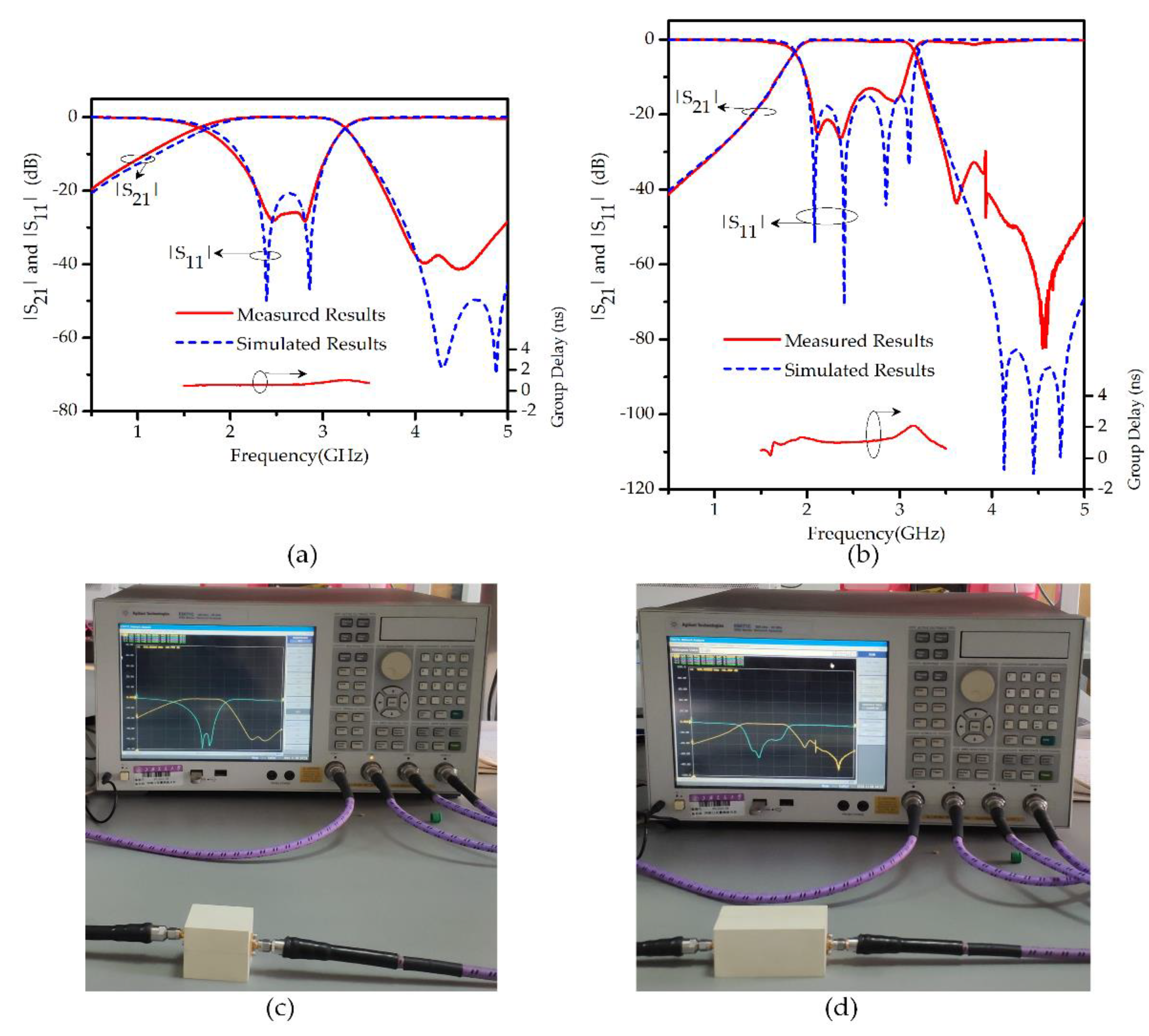
The simulated and measured results of the reflection and transmission coefficients for the second-order and the fourth-order filter employing one and two waveguide cavities respectively are graphed in
Figure 7a,b, respectively. The simulated and measured results agree well with a small deviation, probably caused by losses from the SMA connectors, tolerance in fabrication of the ring resonators, and rectangular metal cavities. The measured group delays of both the filter prototypes show good flatness in their respective wide passbands, as clearly depicted in
Figure 7a,b. The filter responses were measured using the vector network analyzer (VNA) Agilent E5071C. The experimental setup for measuring the results is shown in
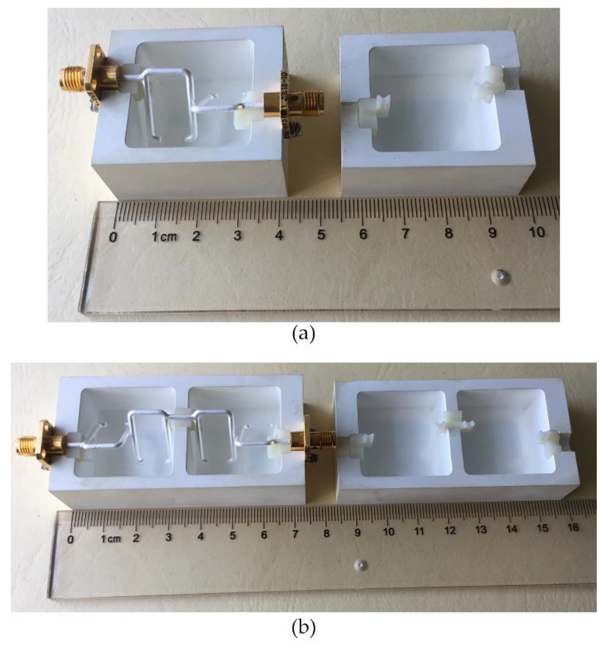
Figure 7c,d. The measured insertion losses of the two filters are less than 0.1 dB while their measured return losses are better than 20 dB and 14 dB, respectively. The measured results of the two figures show a decent stopband rejection level on both the lower and upper side of the passband. The proposed wideband bandpass multi-mode filter is designed at the center frequency of 2.5 GHz with 53% of fractional bandwidth. The photographs of the fabricated one-cavity and two-cavity prototype filters are shown in
Figure 8a,b respectively.
The multi-mode filter is compared with the other similar cavity filters reported in the recent years and the comparison is presented in
Table 1.
5. Conclusions
In this paper, a multi-mode filter with two resonant modes is proposed. Two SRRs connected with the two probes are used to excite the resonant modes in a rectangular waveguide cavity. The prototype filters with one and two-cavity filters are fabricated and the performance of the filters is confirmed with their measured results. The return losses and insertion losses obtained from the measured results are good with wide fractional bandwidths.


