Article

A Fine Frequency Estimation Algorithm Based on Fast Orthogonal Search (FOS) for Base Station Positioning Receivers

School of Electronic Engineering, Beijing University of Posts and Telecommunications, No. 10 Xitucheng Road, Haidian District, Beijing 100876, China
*
Author to whom correspondence should be addressed.
Electronics 2018, 7(12), 376; https://doi.org/10.3390/electronics7120376
Submission received: 15 September 2018 / Revised: 13 November 2018 / Accepted: 21 November 2018 / Published: 3 December 2018

Abstract

:
Base station signals have been widely studied as a promising navigation and positioning signal. The time and code division-orthogonal frequency division multiplexing (TC-OFDM) signal is a novel communication and navigation fusion signal that can simultaneously implement communication and positioning services. The TC-OFDM signal multiplexes the pseudorandom noise (PRN) code, called positioning code, and the Chinese mobile multimedia broadcasting (CMMB) signal in the same frequency band. For positioning in the TC-OFDM receiver, it is necessary to acquire and track the PRN code phase and the carrier frequency. The tracking performance is directly influenced by the accuracy of the signal acquisition, especially the acquired carrier frequency accuracy. This paper focuses on the fine frequency acquisition of TC-OFDM receivers and proposes a novel fine frequency estimation algorithm, which uses a non-linear modelling method, called fast orthogonal search (FOS), to improve the frequency acquisition accuracy of TC-OFDM receivers. With this algorithm, the PRN code is first stripped off in coarse code phase. Then, the candidate functions at each of the interest frequencies are generated, which consist of pairs of sine and cosine terms. Finally, the FOS algorithm is used to detect the carrier frequency. Simulation and experimental results show that, compared with the current carrier frequency estimation algorithms, the proposed algorithm effectively improves carrier frequency estimation accuracy and then reduces the time to the first fix.

1. Introduction

Base station signals provide a wide range of outdoor and indoor signal coverage in the city, which are suitable for positioning [1]. The base station positioning system (BSPS) can complement the global navigation satellite system (GNSS) in areas where satellite signals cannot be directly received. However, the existing BSPS positioning accuracy is generally around 50 m [2], so we developed a novel BSPS called time and code division-orthogonal frequency division multiplexing (TC-OFDM) signal. This system achieves outdoor and indoor positioning over large areas under 3 m. Refs. [3,4] described the TC-OFDM system in detail. The TC-OFDM system is based on the existing China mobile multimedia broadcasting (CMMB) system, which is divided into two parts: communication and positioning. The communication part is the existing CMMB system without modification, and the positioning part is a direct-sequence spread spectrum code division multiple access (DSSS-CDMA) system employing binary phase shift keying (BPSK) modulation. The CMMB signal and Pseudorandom Noise (PRN) codes are multiplexed in the same frequency band, and the basic location information about the base station is added. The basic location information is called the navigation message, which includes coordinated universal time, base station number, air pressure, and base station coordinates. As the reception sensitivity of the CMMB receiver is −95 dBm [5] and the CMMB base station is covered by a single frequency network [6], the TC-OFDM receiver achieves positioning by demodulating PRN codes.
As with GNSS receivers, the TC-OFDM receiver performs the acquisition as the first stage of the digital processing [7], and the accuracy of the signal acquisition directly influences the tracking performance. The acquisition process involves acquiring the PRN code phase and the carrier frequency of the TC-OFDM signals, which is important for successful TC-OFDM signal tracking. The TC-OFDM positioning signal consists of two different lengths of PRN codes: short codes and the long codes. Since carrier frequency has little influence on the short code correlation, the TC-OFDM signal acquisition can obtain the PRN code phase by directly detecting the short code correlation [8]. Carrier frequency can be acquired by using the TC-OFDM signal that is stripped off long codes. Then, these necessary parameters obtained by the acquisition process pass to the tracking process. Thus, the acquisition accuracy directly influences the tracking performance. The signal acquisition is the most time-consuming procedure compared with the other procedures of the receiver, which is the main reason that affects the time to the first fix (TTFF). The PRN code acquisition using a parallel matched filter leads to considerable consumption of the field programmable gate array (FPGA) hardware resource, so the existing TC-OFDM receiver adopts FPGA and Acorn RISC Machine (ARM) composite structure for cost savings. The ARM adopts the AT91SAM9G20 chip produced by Atmel (San Jose, CA, USA) and its maximum clock speed is up to 400 MHz, which satisfies the requirement of the tracking loop parameter calculation and the parameter transmission between the FPGA and the ARM. Due to the limitations of FPGA hardware resources and the advantages of ARM floating-point arithmetic, the parallel residual carrier frequency searching (PRCFS) algorithm is used to estimate the carrier frequency in the existing TC-OFDM receiver [9]. The PRCFS algorithm calculates the correlation values of the fixed frequencies in parallel and selects three maximum correlation values. The quadratic curve fitting algorithm is used to determine the frequency estimation value. In order not to increase the consumption of hardware resources, the PRCFS algorithm uses tracking channel resources when the tracking process is not performed. However, this requires more time to obtain a high accuracy carrier frequency estimation under the condition of limited parallel correlations, and it increases the TTFF. In order to make the TTFF more reasonable, the accuracy of the carrier frequency estimation is usually lower.
There are several algorithms available to improve the acquisition carrier frequency accuracy for the receivers employing BPSK modulation, such as the GNSS receiver. The current fine frequency estimation algorithms can be divided into two categories: one-step algorithms and coarse-to-fine algorithms [10,11,12,13,14,15,16,17]. One-step algorithms use long data to calculate the carrier frequency, which include time-domain correlation and frequency-domain circular correlation [10,11,12]. Since the carrier frequency accuracy improves with increasing data length, long computational time and navigation message bit transition are the main disadvantages. In addition to the above two reasons, the periodic broadcast of short codes is also the reason why the algorithm that increases the data length is not used to improve the carrier frequency estimation accuracy in the TC-OFDM receiver. As for coarse-to-fine methods, short codes are used to estimate the coarse PRN code phase of the incoming signals. Then, the long-code-stripped signals are utilized to accurately acquire carrier frequency.
Due to the periodic broadcast of short codes, the methods to increase the data length to improve the carrier frequency estimation accuracy are limited in the TC-OFDM receiver. Ref. [13] used fast Fourier transformation (FFT) to process the long-code-stripped data, but it had the same above drawbacks as well as increasing hardware resource consumption. The fine method can use frequency locked loop (FLL), but the FLL requires a long time to become steady enough to allow its transition into the phase locked loop (PLL) [14]. Ref. [15] introduced a fine frequency estimation method based on carrier phase differences, but it is seriously affected by the signal-to-noise ratio (SNR) and fails in low SNR cases. Ref. [16] refined the carrier frequency after a parallel code-phase search via triangle fitting of the cross-ambiguity function, but the performance of the proposed algorithm requires a long integration time, which leads to an increase in the TTFF. Ref. [17] proposed a novel frequency estimator for the frequency estimation of a complex sinusoid weighted with a rectangular window function, which can be flexibly applied in engineering applications. However, in Ref. [17], the performance of the proposed algorithm depended on the parameter selection associated with the rectangular window function.
In this paper, considering the special structure of the TC-OFDM receiver, a novel fine frequency estimation algorithm based on fast orthogonal search (FOS) is proposed to accurately acquire carrier frequency. The operation of the proposed algorithm is implemented in the ARM, and it does not require the hardware resources of the FPGA. After coarse acquisition process completed the coarse code phase, the long codes are first stripped off. Then, the candidate functions at each of the interest frequencies are generated. Lastly, carrier frequency is detected by FOS. Simulations and experimental tests were performed to verify the reliability of the proposed algorithm. Simulation results demonstrate that the frequency estimation error of the proposed algorithm is less than 10 Hz, which effectively accelerates the convergence rate of carrier frequency. The FPGA hardware resources of the existing receiver are limited, and other FFT-based algorithms consume huge amount of hardware resources. Then, the PRCFS and the FFT-based carrier frequency estimation algorithm are only used for comparison, and experimental results show that the TTFF of the proposed algorithm is less than that of the PRCFS algorithm.
The remainder of this paper is laid out as follows. In Section 2, the TC-OFDM system model is presented and the coarse acquisition process is given. In Section 3, a novel algorithm for fine frequency estimation of TC-OFDM receivers is proposed based on coarse acquisition. Simulation and experimental results are shown and analyzed in Section 4. Section 5 concludes the work.

2. System Model and Coarse Acquisition

In this section, the mathematical model of the TC-OFDM signal and the coarse acquisition of the TC-OFDM receiver are presented. The acquisition process of the coarse PRN code phase is analyzed.

2.1. System Model

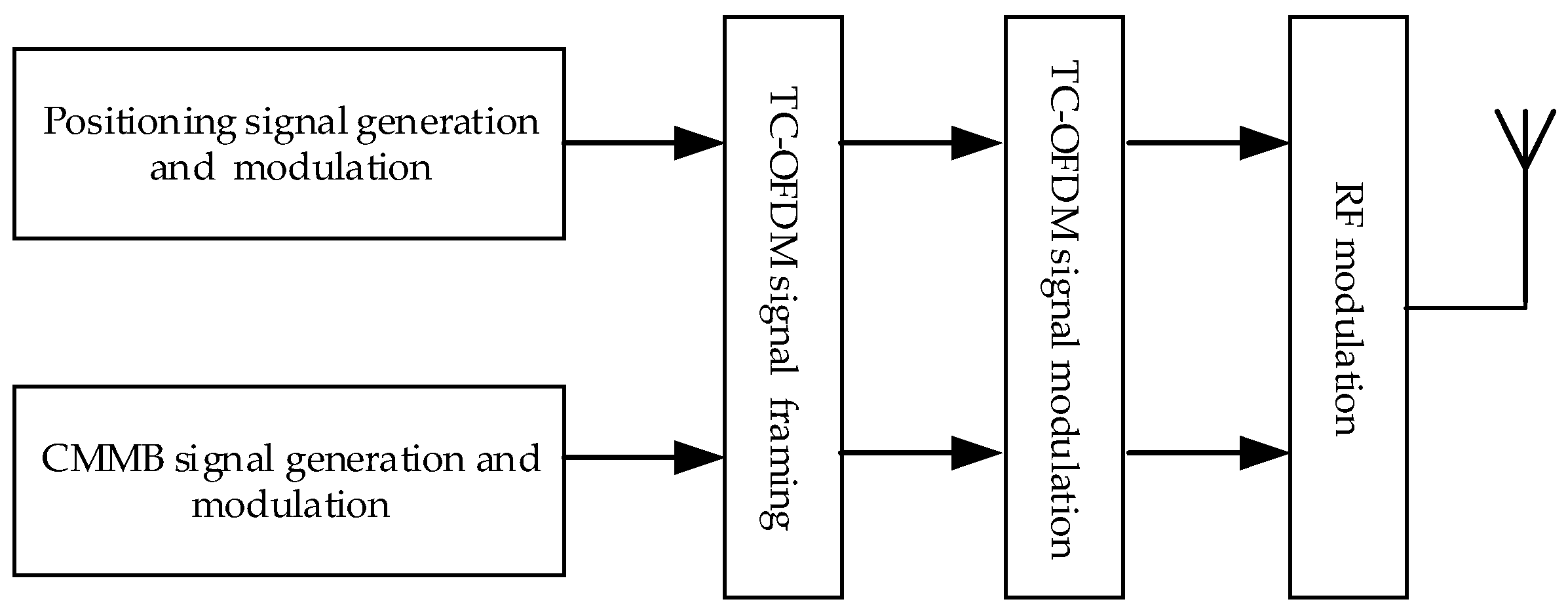
The TC-OFDM system we developed is a communication and positioning fusion system, which can simultaneously perform communication and positioning. The positioning part of the TC-OFDM system is a DSSS-CDMA system employing BPSK modulation. Figure 1 shows the structure of one TC-OFDM signal frame. The CMMB signal is a digital broadcast signal based on original orthogonal frequency division multiplexing (OFDM). One frame of the CMMB signal has 40 time slots, and each time slot includes a TxID signal, synchronization signals and OFDM symbols [18]. The positioning signal includes two different lengths of PRN codes. These two signals are multiplexed in the same frequency band and are broadcasted together by the modified digital broadcasting base station (MDBBS). Considering that the TxID of the used CMMB signal is empty, short codes are inserted into the beginning of each digital broadcast signal time slot, and the power is as strong as the digital broadcast signal. The long code power is lower than the OFDM signal, at 18 dB, which can reduce the positioning signal interference on the communication signal and ensure the normal communication service. The communication system and the positioning system use the same 1 pps pulse signal to control the TC-OFDM signal broadcasting, so ensures the synchronization between MDBBSs. Figure 2 shows the TC-OFDM signal generation process. The PRN code rate is 5 MHz and each frame of the CMMB signal is 25 ms. The navigation message is modulated onto the PRN code by employing BPSK modulation; the navigation message rate is 40 Hz and the complete navigation message consists of 800 bits. Since the CMMB signal bandwidth is 8 MHz and avoids interference with the surrounding frequency, the signal bandwidth of the TC-OFDM signal is also 8 MHz.
The kth time slot of TC-OFDM signal is expressed as:
s k ( i ) ( t ) = { s O F D M ( t ) + c S ( i ) ( t ) k T F t < k T F + T S C s O F D M ( t ) + c L ( i ) ( t ) k T F + T S C t < ( k + 1 ) T F 0 o t h e r s
where i is the number of the MDBBS; s O F D M ( ) is the OFDM symbol; c S ( i ) ( ) and c L ( i ) ( ) stand for the short and long codes of i-MDBBS, respectively; and T F and T S C are the time slot duration and the duration of short codes, respectively. The Radio Frequency (RF) signal sent by i-MDBBS is written as
S ( i ) ( t ) = k = d k ( i ) ( t ) s k ( i ) ( t ) cos ( 2 π f c t + θ )
where d k ( i ) ( ) denotes the navigation message of i-MDBBS, f c is the carrier frequency, and θ is the initial phase.

2.2. Coarse Acquisition

The TC-OFDM receiver receives TC-OFDM signals from MDBBSs, and the received signals are converted to intermediate frequency signals r(n) through the mixer, filter, and analog-to-digital converter (ADC) model. r(n) is expressed as:
r ( n ) = i = 1 N A 0 ( i ) d ( i ) ( n T s ) c p ( i ) ( n T s τ ( i ) ) e j 2 π ( f I F + f d ( i ) ) n T s + φ ( i ) + v ( n T s )
where A 0 is the signal amplitude, T s is the sampling time, N is the total number of the MDBBS signal received, c p is the positioning signal including short codes and long codes, τ is the code delay of the received signal, f I F is the intermediate frequency, f d is the residual carrier frequency, φ is the initial phase, and v ( ) is the additive white Gaussian noise (AWGN) component with zero mean (μ = 0) and variance ( σ n 2 ). Then, r(n) is converted into i(n) and q(n) to the baseband processor after the down-converter and the low pass filter. For the sake of discussion, we assumed that only one MDBBS signal is received. Coarse acquisition techniques used inside the receivers are based on the cross ambiguity function (CAF) to acquire the code phase by the short codes, as shown in Figure 3. L is the length of the short code with the correlation operation, C L 1 is the local code, and I(n) and Q(n) are the correlation values. The final output is:
V ( n ) = A 2 ( n ) R S 2 ( τ ) sinc 2 ( T c o h f d ) + ω 2 ( n )
where A ( ) is the amplitude including the unknown sign of the navigation message bit, R S ( ) stands for the autocorrelation function of short codes, τ is the code offset between the received signal and the local replica code, sinc ( ) is the sinc function, T c o h is the coherent integration time, and ω ( ) is white Gaussian noise (WGN) having zero mean and unity variance. In the ideal case, the normalized R S ( ) can be expressed as:
R S ( τ ) = { 1 | τ | / T c | τ | T c 0 o t h e r s
where T c is the chip duration. In the MDBBS, the positioning signal is filtered into the same bandwidth as the CMMB signal. The bandwidth of the TC-OFDM receiver is limited. The expression R S ( ) , affected by the limited bandwidth, is as follows:
R S ( τ ) = B B G P ( f ) e j 2 π f τ d f
where B is the signal transmission bandwidth and G P is the normalized power spectral density of c p . G P is expressed as:
G P ( f ) = T c sinc 2 ( π f T c )
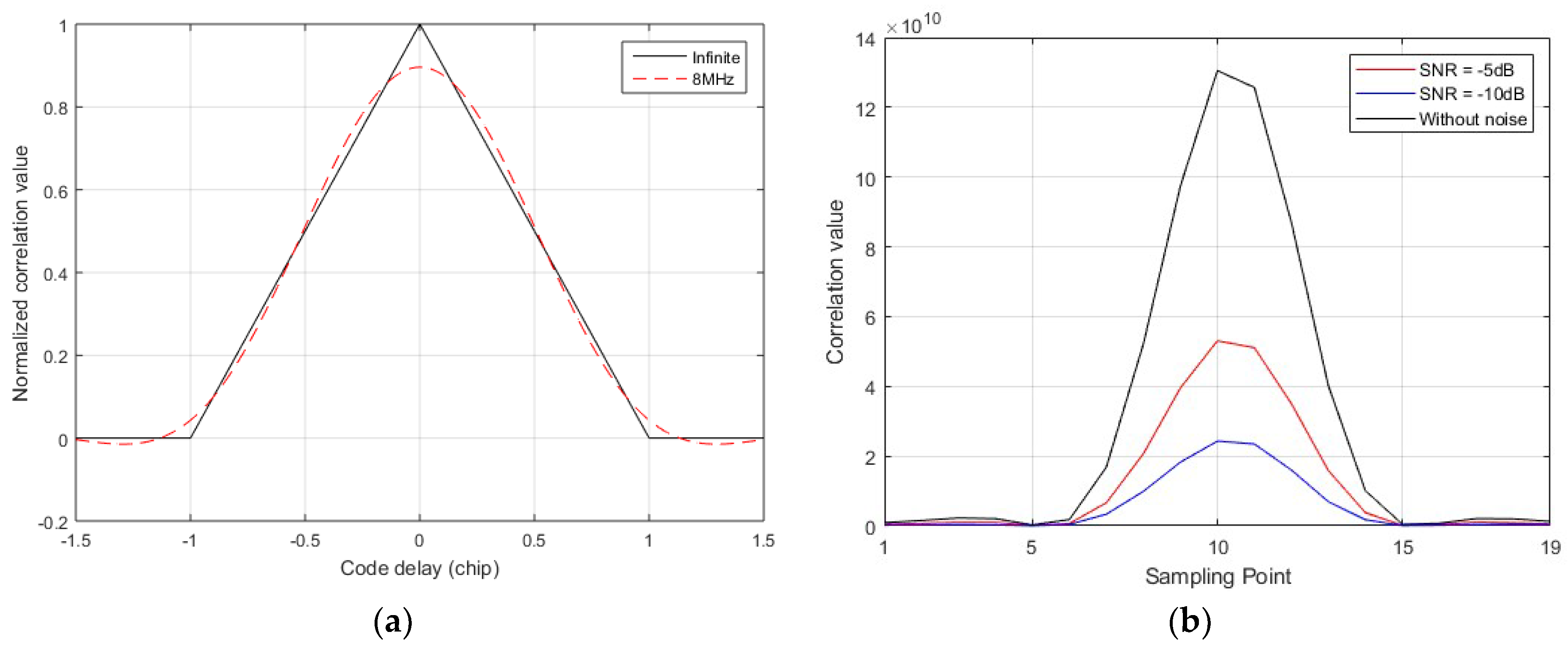
where T c is one PRN code duration. When T c = 200 n s , R S ( ) under different signal transmission bandwidths and SNR is shown in Figure 4. The limited bandwidth results in a 10% drop in the peak of the autocorrelation function, but WGN causes a drop in the correlation function peak of at least 30%. Therefore, although the limited bandwidth reduces the peak value of the autocorrelation function, the impact on the acquisition is much smaller than that caused by noise, and we ignored the impact caused by the limited bandwidth in this research. Once the CAF is evaluated, V(n) makes a decision regarding the presence or absence of the searched MDBBS by comparing with the predefined threshold. The predefined threshold is two times larger than the second peak value of the short code duration in this research.

3. Proposed Fine Frequency Estimation Algorithm

After the acquisition process was accomplished, the coarse code phase was performed, while carrier frequency could not be obtained. In this section, a novel fine frequency estimation algorithm based on FOS is proposed to acquire accurate carrier frequency.

3.1. Overview of the Proposed Algorithm

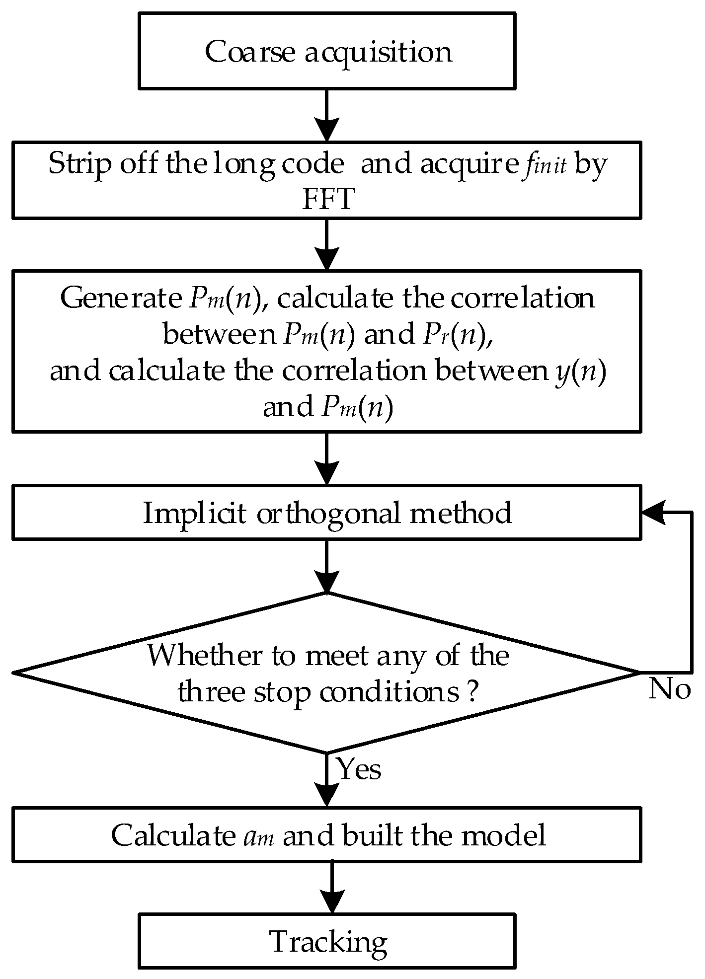
The flowchart of the proposed algorithm is shown in Figure 5. Firstly, the transmitting base stations are determined by performing an acquisition algorithm, as shown in Figure 3, on the received signals, and the code phase is achieved. Then, the long code is stripped off, and an initial frequency is obtained by performing FFT operation on the received signal stripped the pseudo code. Secondly, the interest frequencies are achieved based on the initial frequency, and the candidate functions are obtained. Thirdly, a functional expansion of the stripped signal is created by choosing the best basis functions from all candidate functions. In order to reduce the time and storage memory consumption, we used the implicit orthogonal method to choose the best basis functions and the corresponding weights. Finally, when any of the stop conditions of the implicit orthogonal method are met, the stripped signal expression is constructed using the selected candidate functions to determine the final carrier frequency value; otherwise, the implicit orthogonal method continues. The following is a detailed derivation of the proposed algorithm.

3.2. Coarse Acquisition

Long codes are stripped off from the received TC-OFDM signal when the coarse code phase has been acquired. FFT is used to find coarse carrier frequency. The long-code-stripped data are sent to the FFT module for the coarse carrier frequency calculation. The FFT resolution is defined as follows:
f d = f s N F F T = f s f s T r = 1 T r
where f s is the sampling frequency, N F F T is the FFT point number, and T r is the recording time. In order to achieve higher frequency and better de-noising, the candidate function spacing is set as 1/10 the FFT resolution in this research. Generally, the width of the tracking loop is less than 10 Hz. Therefore, FFT resolution is 100 Hz and candidate function spacing is 10 Hz. In order to find 100 Hz resolution, 10-ms long-code-stripped data are required to be recorded. The recorded data are then input into the FFT model to obtain the coarse carrier estimated frequency.
The proposed method is accomplished by selecting appropriate candidate functions P k ( n ) . P k ( n ) are pairs of sine and cosine terms at each of the interest frequencies and expressed as:
{ P 2 k ( n ) = cos ( 2 π f k n ) P 2 k + 1 ( n ) = sin ( 2 π f k n )
where k = 0 , , N P 1 , N P is the number of candidate pairs and f k is the interest frequency. f k is given by:
{ f m = f i n i t + ( k ( N P + 1 ) / 2 ) Δ f Δ f = 2 f d / ( N p + 1 )
where f i n i t is the estimated coarse carrier frequency by FFT, f d is the interval between two FFT bins, and Δ f is the interval between adjacent candidate pairs. Figure 6 describes the relationship among the frequency parameters above. The FOS algorithm uses f k to create the frequency estimation function with high accurate. Δ f is much smaller than f d , so the FOS algorithm can create a new function to estimate the carrier frequency with high accuracy.

3.3. High Resolution Carrier Frequency Estimation

FOS algorithm has a lot of practical applications including spectral model estimations, time series analysis and non-linear system control [19,20,21,22], and the proposed algorithm is based on FOS algorithm. The main goal of the proposed algorithm is to create a functional expansion of an input y ( n ) by choosing the best basis functions from all candidate functions P k ( n ) , in order to minimize the mean squared error (MSE) between y ( n ) and the functional expansion. y ( n ) can be linear combinations of P k ( n ) and written as:
y ( n ) = k = 0 K a k P k ( n ) + ε ( n )
At the beginning of the FOS algorithm, an orthogonal transform method is applied to the model presented in Equation (11), and then the created functional expansion is expressed as:
y ( n ) = k = 0 K g k w k ( n ) + e ( n )
where g k is the weight of the orthogonal functions w k ( n ) , e ( n ) denotes the residual error, and w k ( n ) is a set of orthogonal functions derived from P k ( n ) by utilizing the Gram Schmidt orthogonalization algorithm.
w i ( n ) w j ( n ) ¯ = 0 , i j
The calculation process is as follows:
w 1 ( n ) = P 1 ( n ) = 1 w 2 ( n ) = P 2 ( n ) α 21 w 1 ( n ) w k ( n ) = P k ( n ) r = 1 k 1 α k r w r ( n )
The Gram-Schmidt coefficient α k r is:
α k r = P k ( n ) P r ( n ) ¯ w r 2 ( n ) ¯
However, the above orthogonal function calculation is very time consuming and requires large storage memory. To avoid these problems, the FOS algorithm uses the implicit orthogonal method, which only needs to calculate α k r instead of calculating w k ( n ) point-by-point. α k r and g k are derived recursively using the following equations [18]. In order to intuitively represent the relationship between the following equations, the intermediate functions C ( k ) and D ( k , r ) are created.
{ D ( 0 , 0 ) = 1 D ( k , 0 ) = P k ( n ) ¯ D ( k , k ) = w k 2 ( n ) ¯ D ( k , r ) = P k ( n ) w r ( n ) ¯ = P k ( n ) P r ( n ) ¯ i = 0 r 1 α r i D ( k , i )
α k r = P k ( n ) P r ( n ) ¯ w r 2 ( n ) ¯ = D ( k , r ) D ( r , r )
{ C ( 0 ) = y ( n ) ¯ C ( k ) = y ( n ) w k ( n ) ¯ = y ( n ) P k ( n ) ¯ r = 0 k 1 α k r C ( r )
g k = C ( k ) D ( k , k )
where k = 1 , , K ; r = 1 , , k .
In the last stage, a m can be derived recursively using the following form:
a k = i = k K g i v i
where
v i = { 1 i = k r = k i 1 α i r v r k < i K
In order to build an efficient model with few terms, each P k ( n ) is fitted as the first candidate function to test in the Gram Schmidt orthogonal model. The candidate function pair that reduces the MSE of the model most is selected as the first candidate function in the orthogonal model. Next, all the rest of the candidates are fitted as the second candidate function pair to test in the orthogonal model. Again, the candidate function pair with the maximum reduction in MSE is selected next to fit the model.
The MSE of the Gram Schmidt orthogonal model can be expressed as:
ε 2 ( n ) ¯ = y 2 ( n ) ¯ k = 0 K g k 2 w k 2 ( n ) ¯
Then, the MSE reduction caused by the kth candidate function can be written as:
Q k = g k 2 w k 2 ( n ) ¯ = g k 2 D ( k , k )
The proposed method is stopped in one of the following three cases:
(1)
A certain maximum number of terms is fitted;
(2)
The predetermined threshold is higher than the ratio of MSE to the mean squared value of y ( n ) ; or
(3)
Adding another term to the model makes the MSE reduction less than adding WGN.
Additionally, a predetermined threshold is set, and it needs a candidate function pair to fit a minimum percentage of the total signal energy. The threshold allows the FOS to model the motion dynamics and reject candidate functions that model the WGN. The output of the proposed algorithm is the carrier frequency estimation, and then the local carrier loop is renewed. Finally, the TC-OFDM receiver begins to stably track the received signal.

4. Performance and Analysis

The FOS-based fine frequency estimation algorithm was primarily developed to improve the carrier frequency estimation accuracy and then reduce the TTFF. In this section, simulations and experimental tests are performed to verify the proposed algorithm. In addition, the results of the proposed algorithm are compared to those from other frequency estimation algorithms.

4.1. Simulations

Monte Carlo simulations were used to evaluate the comprehensive performance of the FOS-based fine frequency estimation algorithm. The PRCFS algorithm, the FFT algorithm (contains the conventional FFT algorithm and the radix-2 FFT algorithm), and the FLL algorithm were simulated to compare their performance of that of the proposed algorithm. The radix-2 FFT algorithm is used in the GNSS receiver for the convenience of FPGA operation, which usually uses the zero padding method to convert the input data of the FFT module into the radix-2 data. The zero padding FFT method is called FFT-ZP. All the simulations were implemented by MATLAB R2015a, and repeated 100 times to obtain good statistical properties. These simulation results are based on the signal model described in Equation (3). The PRN code signal adopted Gold codes, and the length of the long code was 8191 chips. Moreover, we created an experimental environment in our campus, as shown in Figure 7. The sampling rate of the TC-OFDM radio front end was 22 MHz, and the output signal did not have an intermediate frequency carrier. In order to avoid the residual carrier frequency being an integral multiple of the FFT resolution and PRFCS resolution, we set several special frequencies for simulation, and these residual carrier frequencies are shown in Table 1. After analyzing the TC-OFDM signals from the MDBBSs, we found that the SNR of the received signals was generally −25 dB to −30 dB, and we chose the boundary value for simulation. In this research, the noise bandwidth of FLL was 5 Hz and the noise bandwidth of PLL is 10 Hz, which optimized the tracking performance. Table 1 is a list of all simulation parameters.
The interval between two possible frequency points of PRCFS was 300 Hz, the traditional FFT resolution was 610 Hz, and the FFT-ZP ( i × 16 ) resolution was f s / 2 i × 16 . Considering the frequency resolution of the five different algorithms, we chose the special frequencies mentioned above to verify the advantages of the proposed fine frequency estimation algorithm. If the search frequency bin of PRCFS or FFT is close to f d , the carrier frequency estimation error of PRCFS or FFT is small. Firstly, the frequency estimation errors of the five algorithms were simulated in the conditions of same SNR and f d . Figure 8 and Figure 9 show the frequency estimation errors of the five different algorithms, where the total data length of the FFT-ZP ( i × 16 ) was L = 2 i × 16 . From Figure 8 and Figure 9, it can be found that the PRCFS algorithm was dependent on SNR, and the frequency estimation error deviating from the set frequency point was larger at lower SNR. At the condition f d = 775   Hz , the error of two PRCFS estimations corresponding to different SNR was 50 Hz. Due to the PRCFS using periodic long codes to coherently integrate the carrier frequency estimation, the noise had a great influence on the coherent integration result at lower SNR. If signal fading occurs during the correlation duration, the computational reliability of the PRCFS algorithm may be reduced. The FFT spectral resolution can be significantly improved by zero-padding, but this leads to additional computational time and consumption of hardware resources. Although the frequency estimation errors of the FFT-ZP ( 3 × 16 ) and the proposed algorithm were very close, the computational time of the FFT-ZP ( 3 × 16 ) was higher than that of the proposed algorithm. FFT-ZP ( 3 × 16 ) consumes more FPGA hardware resources than the proposed algorithm in the receiver of FPGA and ARM composite structure. The proposed algorithm improves the frequency estimation accuracy by more than 10% compared with other carrier frequency estimation algorithms at the same SNR and f d .
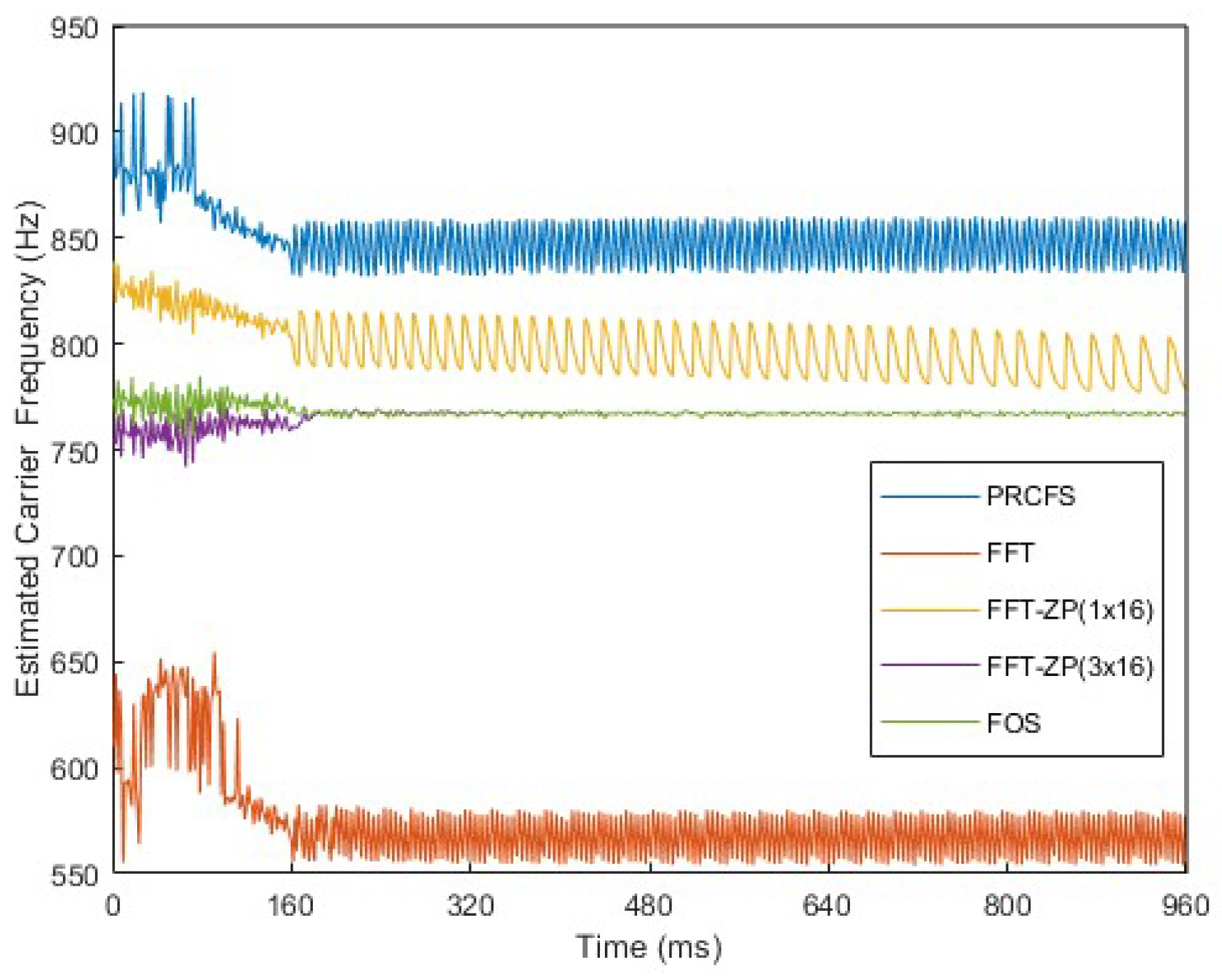
Secondly, we simulated the carrier converging processes of the five different frequency estimation algorithms. To avoid the impact of PLL on carrier tracking, FLL was only used to track the carrier to test the effects of different algorithms on the tracking process. Figure 10, Figure 11 and Figure 12 illustrate the results of the converging process of FLL after setting initial carrier frequency estimations of the five algorithms at same the SNR and f d . As shown in Figure 10, when the initial carrier frequency estimation error was large, the FLL converged to an erroneous frequency, and eventually the loss of the carrier tracking loop occurred. The process and statistics of the carrier convergence of the first 160 ms were amplified and statistically analyzed, and the statistical standard deviation (SD) results are shown in Table 2. The SDs of the FFT-ZP ( 3 × 16 ) and the proposed algorithm were the smallest. In other words, these two algorithms make the FLL converge to the correct frequency the fastest. The smaller the initial carrier frequency estimation error, the shorter the FLL convergence time. In Figure 10 and Figure 11, the proposed algorithm made the FLL converge to the correct carrier frequency more quickly than the other algorithms under different residual carrier frequencies. Compared with Figure 11 and Figure 12, although the estimated carrier frequency fluctuations increased as the SNR decreased, the proposed algorithm made FLL with fast convergence to the correct carrier frequency under different SNR.
In the tracking process of the TC-OFDM receiver, FLL is the conversion process running in a transient period. The duration of the transient period can be an engineering experience value or an automatically adjustment [23,24]. After the FLL converges, the receiver begins to track the carrier frequency with higher accuracy using the PLL. The duration of the transient period was set as an engineering experience value in this research. When the duration of the transient period was over, the FLL was automatically switched to the PLL. In Figure 13, the carrier signal is tracked with FLL for the first 160 ms, and followed by the PLL. It can be seen that the proposed algorithm and FFT-ZP ( 3 × 16 ) converge quickly to the correct carrier frequency, and then achieve stable tracking with small fluctuations. However, in the test, we found that the computation time of the FFT-ZP was longer than that of the FOS. As a result, the proposed algorithm solves the balance between acquisition accuracy and computational time, and then reduces the TTFF.

4.2. Experimental Tests

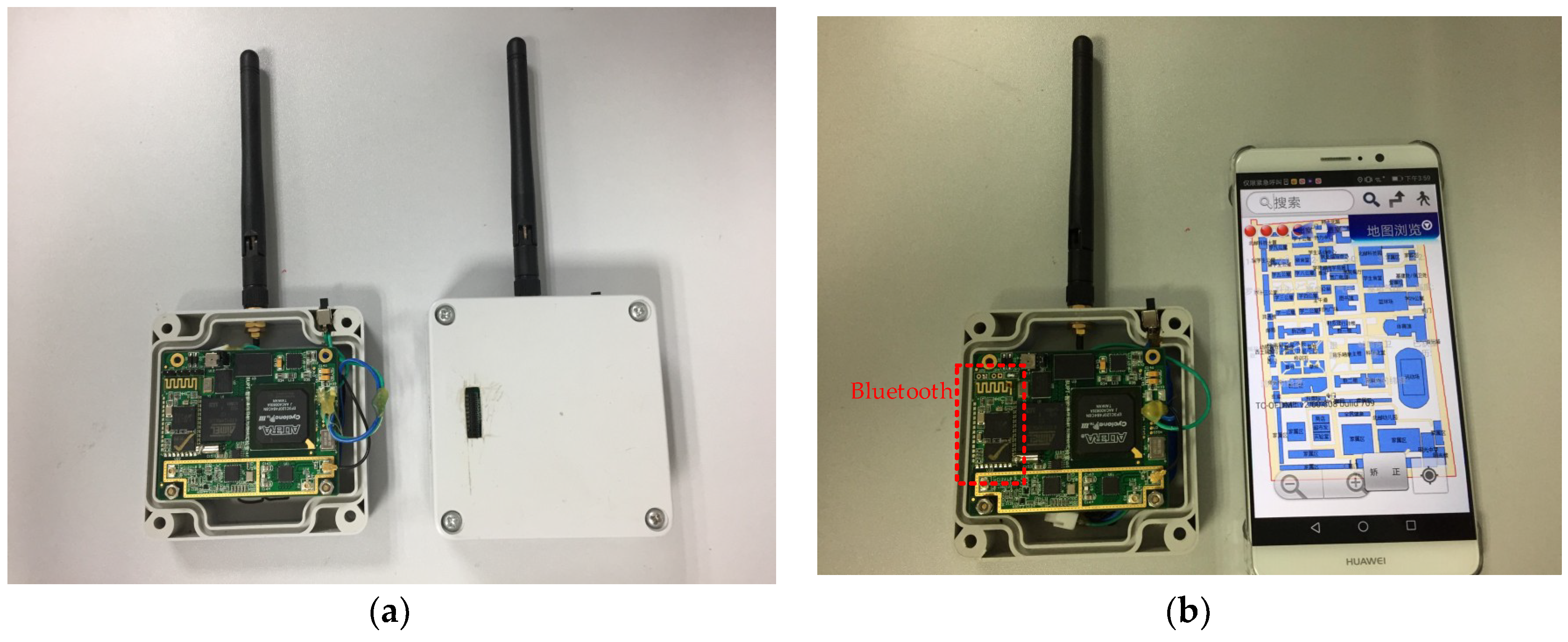
To confirm that the proposed fine frequency estimation algorithm has better actual performance, experimental tests were performed in the campus environment shown in Figure 7. There were four MDBBSs on the roofs of the selected four buildings. All equipment of the MDBBS is shown in Figure 14. The outputs of the atomic clock are two clock frequency signals and one second pulse signal, which achieve a 5-ns-accurate synchronization between different MDBBSs. The actuator had a navigation message generator and a fusion signal generator, and the transmitter transmitted the RF signal. We selected 10 points to test the TTFF in the test building, and these test points were places on the window edges of the fourth floor, which were less affected by the multipath and non-line of sight. Figure 15 shows the structure of the TC-OFDM receiver. The positioning data calculated by the receiver were transmitted via Bluetooth to the mobile phone and displayed on the mobile phone. For cost-savings, the receiver adopted the FPGA and ARM composite structure, and the operations with high real-time requirements were completed in FPGA. The proposed algorithm requires multiple non-integer multiplication and addition operations, and the ARM is especially suitable for floating point operations. Therefore, the proposed algorithm was implemented in ARM, and it basically does not consume the hardware resources of the existing receiver.
Due to the limited remaining hardware resources of the existing receiver, we downloaded the PRCFS algorithm, the FFT-ZP ( 1 × 16 ), and the proposed algorithm to the identical receivers. These three receivers were tested 10 times at each selected point. Each time from the boot to the first fix was recorded, and the recorded data were transmitted to the corresponding mobile phones via Bluetooth. The results of the TTFF are shown in Figure 16. Although the proposed algorithm resulted in an increase in the machine instructions, the increase was found to be acceptable for the tracking process. When the other algorithms were the same except for the different fine frequency estimation algorithms, TTFF was the most intuitive comparison parameter. Due to the randomness of the noise and the order of the received navigation message bits, the TTFF of the selected points were different. The TTFF of the proposed algorithm was less than that of the two comparison algorithms, and the fluctuation in the TTFF of the proposed algorithm was smaller than those of the comparison algorithms, which shows that the noise suppression ability of the proposed algorithm is better than that of the comparison algorithms. In most cases, the TTFF of the receiver using the FFT-ZP ( 1 × 16 ) was smaller than that of the PRCFS algorithm. The reason for this finding is that the gain produced by FFT operation can suppress WGN, which can reduce the impact of the noise on the carrier estimation. However, in some cases, the performance of the receiver using the PRCFS algorithm was better, mainly because the residual carrier frequency was far from the integer multiple of the FFT resolution. The proposed algorithm can reduce the TTFF of the existing TC-OFDM receiver and maintain the balance between acquisition accuracy and computational time.

5. Conclusions

The TC-OFDM signal is a novel base station positioning signal based on the CMMB system. This paper proposed a novel FOS-based fine frequency estimation algorithm that estimates the carrier frequency with high accuracy for TC-OFDM receivers. This algorithm identified a nonlinear system and established the corresponding estimation model, which better estimated the carrier frequency of TC-OFDM receivers. The simulation results demonstrated that the proposed algorithm improves the frequency estimation accuracy and the convergence speed of the carrier loop. Most of the operation of the proposed algorithm is implemented in ARM; the novel algorithm requires less FPGA hardware resources and is suitable for existing TC-OFDM receivers. The experimental results showed that the proposed algorithm reduces the TTFF and maintains the balance between acquisition accuracy and computational time. Although this algorithm was described in the context of TC-OFDM receivers, it can be applied to a DSSS-CDMA system employing BPSK modulation.

Author Contributions

Z.D. and J.M. are both the principal investigators; B.J. and X.B. assisted J.M. to conceive and conduct the experiments and analysis; and J.M. analyzed the data and wrote the paper.

Funding

This research was funded by the Science and Technology Planning Project of Guangdong Province of China (No. 2017B090908005), and the National Key R&D Plan of China (No. 2016YFB0502001 and No. 2016YFB0502003).

Conflicts of Interest

The authors declare no conflict of interest.

References

  1. Chen, L.; Yang, L.; Yan, J.; Chen, R. Joint Wireless Positioning and Emitter Identification in DVB-T Single Frequency Networks. IEEE Trans. Broadcast. 2017, 63, 577–582. [Google Scholar] [CrossRef] [Green Version]
  2. Kong, S.; Kim, B. Error Analysis of the OTDOA from the Resolved First Arrival Path in LTE. IEEE Trans. Wirel. Commun. 2016, 15, 6598–6610. [Google Scholar] [CrossRef]
  3. Deng, Z.; Yu, Y.; Yuan, X.; Wan, N.; Yang, L. Situation and Development Tendency of Indoor Positioning. China Commun. 2013, 10, 42–55. [Google Scholar] [CrossRef]
  4. Deng, Z.; Mo, J.; Jia, B.; Bian, X. A Pseudorange Measurement Scheme Based on Snapshot for Base Station Positioning Receivers. Sensors 2017, 17, 2783. [Google Scholar] [Green Version]
  5. GY/T 220.7-2008. Mobile Multimedia Broadcasting (PR China) Part 7: Technical Specifications for Receiving and Decoding Terminal; The State Administration of Radio, Film, and Television of China: Beijing, China, 2008. [Google Scholar]
  6. GY/T220.1-2006. Mobile Multimedia Broadcasting (PR China) Part 1: Framing Structure, Channel Coding and Modulation for Broadcasting Channel; The State Administration of Radio, Film, and Television of China: Beijing, China, 2006. [Google Scholar]
  7. Zhu, C.; Fan, X. A Novel Method to Extend Coherent Integration for Weak GPS Signal Acquisition. IEEE Commun. Lett. 2015, 19, 1343–1346. [Google Scholar] [CrossRef]
  8. Mo, J.; Deng, Z.; Jiao, J.; Jiang, S.; Yu, S.; Xu, F. Weak Signal Acquisition Algorithm for Indoor Positioning Receiver. In Proceedings of the 7th China Satellite Navigation Conference, Changsha, China, 18–20 May 2016. [Google Scholar]
  9. Deng, Z.; Yuan, X.; Yu, Y.; Lv, Z. A Method and Realization of Parallel Residual Carrier Frequency Searching for Base Station Positioning System. In Proceedings of the 8th International Conference on Wireless Communications, Networking and Mobile Computing, Shanghai, China, 21–23 September 2012. [Google Scholar]
  10. Wang, K.; Jiang, R.; Li, Y.; Zhang, N. A New Algorithm for Fine Acquisition of GPS Carrier Frequency. GPS Solut. 2014, 18, 581–592. [Google Scholar] [CrossRef]
  11. Wu, J.; Hu, Y. The Study on GPS Signal Acquisition Algorithm in Time Domain. In Proceedings of the 4th International Conference on Wireless Communications, Networking and Mobile Computing, Dalian, China, 12–14 October 2008. [Google Scholar]
  12. Tamazin, M.; Noureldin, A.; Korenberg, M.J.; Massoud, A. Robust Fine Acquisition Algorithm for GPS Receiver with Limited Resources. GPS Solut. 2016, 20, 77–88. [Google Scholar] [CrossRef]
  13. Zhong, H.; Ba, X.; Chen, J.; Zhou, H. FFT-based Fine Frequency Estimation for Weak GPS Signal. J. Electron. Inf. Technol. 2015, 37, 2132–2137. [Google Scholar]
  14. Curran, J.; Lachapelle, G.; Murphy, C. Improving the Design of Frequency Lock Loops for GNSS Receivers. IEEE Trans. Aerosp. Electron. Syst. 2012, 48, 850–868. [Google Scholar] [CrossRef]
  15. Sagiraju, P.; Akopian, D.; Valio, A. Fine Frequency Estimation in Weak Signals for GPS Receivers. In Proceedings of the ION NTM Conference, Monterey, CA, USA, 18–20 January 2006. [Google Scholar]
  16. Yichao, G.; Huan, H.; Ran, T.; Yue, W. Weak DSSS Signal Acquisition with Fine Doppler Frequency Estimation. Electron. Lett. 2018, 54, 79–81. [Google Scholar]
  17. Xiang, J.; Wei, C.; Shen, Q. Flexible and Accurate Frequency Estimation for Complex Sinusoid Signal by Interpolation Using DFT Samples. Chin. J. Electron. 2018, 27, 109–114. [Google Scholar] [CrossRef]
  18. Wang, H.; Jian-Hua, G.E.; Hu, J.; Ai, B. An Efficient OFDM Timing Synchronization for CMMB System. IEICE Trans. Commun. 2012, 95, 3786–3792. [Google Scholar] [CrossRef]
  19. El-Shafie, A.; Noureldin, A.; McGaughey, D.; Hussain, A. Fast Orthogonal Search (FOS) Versus Fast Fourier Transform (FFT) as Spectral Model Estimations Techniques Applied for Structural Health Monitoring (SHM). Struct. Multidiscip. Optim. 2012, 45, 503–513. [Google Scholar] [CrossRef]
  20. Korenberg, M.J. Identifying Nonlinear Difference Equation and Functional Expansion Representations: The Fast Orthogonal Algorithm. Ann. Biomed. Eng. 1988, 16, 123–142. [Google Scholar] [CrossRef] [PubMed]
  21. Korenberg, M.J.; Paarmann, L. Applications of Fast Orthogonal Search: Time-Series Analysis and Resolution of Signals in Noise. Ann. Biomed. Eng. 1989, 17, 219–231. [Google Scholar] [CrossRef] [PubMed]
  22. McGaughey, D.R.; Tarbouchi, M.; Nutt, K.; Chikhani, A. Speed Sensorless Estimation of AC Induction Motors Using the Fast Orthogonal Search Algorithm. IEEE Trans. Energy Convers. 2006, 21, 112–120. [Google Scholar] [CrossRef]
  23. Kaplan, E.; Christopher, J. Understanding GPS. Principles and Applications, 2nd ed.; Artech House: Norwood, MA, USA, 2006; pp. 166–173. [Google Scholar]
  24. Tang, X.; Falletti, E.; Presti, L. Fine Doppler Frequency Estimation in GNSS Signal Acquisition Process. In Proceedings of the Satellite Navigation Technologies and European Workshop on GNSS Signals and Signal Processing, Noordwijk, The Netherlands, 5–7 December 2012. [Google Scholar]
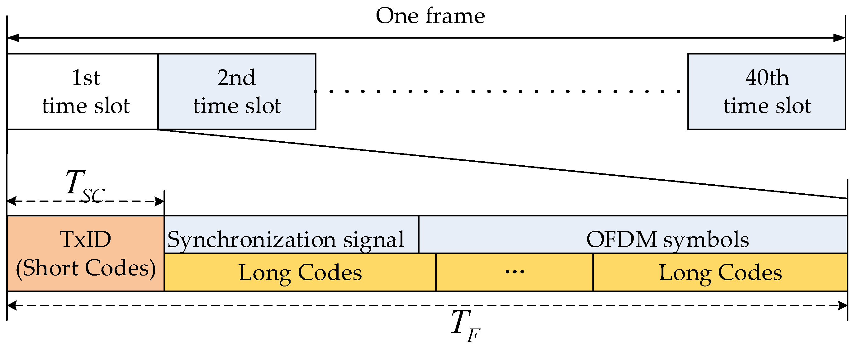
Figure 1. Structure of the fusion signal.
Electronics 07 00376 g001
Figure 2. Coarse acquisition techniques used inside the receivers.
Electronics 07 00376 g002
Figure 3. Structure of the fusion signal.
Electronics 07 00376 g003
Figure 4. The autocorrelation function of short codes: (a) under different bandwidths, (b) under different SNR.
Electronics 07 00376 g004
Figure 5. The flowchart of the proposed algorithm.
Electronics 07 00376 g005
Figure 6. Scheme of determining fm.
Electronics 07 00376 g006
Figure 7. Campus experimental environment and base station distribution.
Electronics 07 00376 g007
Figure 8. Comparison of root mean square of estimated frequency deviation for five algorithm at SNR = −25 dB.
Electronics 07 00376 g008
Figure 9. Comparison of root mean square of estimated frequency deviation for five algorithm at SNR = −30 dB.
Electronics 07 00376 g009
Figure 10. Comparison of converging process of FLL for five algorithms at SNR = −25 dB and f d = 767 Hz.
Electronics 07 00376 g010
Figure 11. Comparison of converging process of FLL for five algorithm at SNR = −30 dB and f d = 567 Hz.
Electronics 07 00376 g011
Figure 12. Comparison of converging process of FLL for five algorithm at SNR = −25dB and f d = 567 Hz.
Electronics 07 00376 g012
Figure 13. Comparison of converging process of FLL to PLL for five algorithms at SNR = −25 dB and f d = 767 Hz.
Electronics 07 00376 g013
Figure 14. All equipment of the MDBSS.
Electronics 07 00376 g014
Figure 15. The TC-OFDM receiver: (a) the internal and external structure of the receiver and (b) positioning data are transmitted to the mobile phone via Bluetooth.
Electronics 07 00376 g015
Figure 16. Comparison of the TTFF of three algorithms of the experimental tests.
Electronics 07 00376 g016
Table 1. Simulation parameters.
ParameterValue
Slot time, T F 25 ms
The time of short codes, T S C 0.136 ms
Bandwidth, B 8 MHz
code rate, f c 5 MHz
Sampling frequency, f s 22 MHz
Intermediate frequency, f I F 0 Hz
Residual carrier frequency, f d 567 Hz, 648 Hz, 767 Hz, 775 Hz, 869 Hz
Signal length10 slot times
SNR−25 dB, −30 dB
The noise bandwidth of FLL5 Hz
The noise bandwidth of PLL10 Hz
Navigation message bits800 bits
Table 2. Standard deviation in carrier frequency at the first 160 ms.
MethodPRCFSFFTFFT-ZP
(1 × 16)
FFT-ZP
(3 × 16)
FOS
SD (Hz)22.55424.08411.4929.6349.627