1. Introduction
Wireless communications are more and more important for our life, and 5G is coming. The 2G, 3G, 4G, and 5G systems will coexist for a long time. Some important bands, such as the LTE700, GSM850, GSM900, DCS, PCS, UMTS, LTE2300, and LTE2500 bands for 2G, 3G, 4G, and the 3.5 GHz band (3400–3800 MHz) that is possible for 5G, should be covered by the mobile antenna. A mobile phone with a small ground clearance and a metal frame is more attractive in the market. However, it is very difficult to design an antenna that can work at multiple bands while keeping a small ground clearance under a metal frame environment.
Many multiple-band antennas for mobile phones with small ground clearances have been proposed in the literature [
1,
2,
3,
4,
5,
6,
7,
8,
9,
10,
11,
12,
13,
14,
15,
16,
17,
18]. There are some useful methods to achieve compact and multiple-band antennas, such as using coupled feeding [
1,
2,
3,
8,
9,
10], lumped elements [
4,
5,
6,
11,
12], and reconfigurable ways [
7,
15,
16,
17]. The antennas in [
1,
2,
3,
4,
6,
7] can work at eight bands, but the 3.5 GHz band is not covered. The antenna in [
5] can work at nine bands including the 3.5 GHz band, but its ground clearance is 10 mm. In addition, the metal frame environment is not considered by the antennas presented in [
1,
2,
3,
4,
5]. The antennas in [
8,
9,
10,
11,
12,
13,
14,
15,
16,
17] can work at multiple bands for a mobile phone with a metal frame, but the antennas in [
8,
9,
11,
13,
14,
15,
16] cannot work at the LTE700 and 3.5 GHz bands. Although the antennas in [
10,
12,
17] can work at the LTE700 band, they cannot work at the 3.5 GHz band. The metal frame antennas mentioned above can work at eight bands, but their ground clearances are not smaller than 7 mm. To the best of our knowledge, there is no metal frame antenna that can work at nine bands with a ground clearance less than 6 mm in the open publications.
In this paper, a metal frame antenna with a size of 75 mm × 6 mm × 6 mm is proposed for 4G and 5G mobile phones. The proposed antenna can work at nine bands including the 3.5 GHz band, which is the possible band for 5G. The proposed antenna consists of a coupled line, a ground branch, a monopole branch, and a tuning line. The ground branch and the coupled line are used to obtain the lower band (698–960 MHz), the monopole branch is used to improve the match at the lower band and obtain the higher band (1710–2690, 3400–3800 MHz), and the tuning line is used to improve the match at the higher band. A prototype is fabricated and measured. According to the measured results, the proposed antenna can work at the LTE700, GSM850, GSM900, DCS, PCS, UMTS, LTE2300, and LTE2500 bands and the 3.5 GHz band. It is suitable for 4G and 5G metal frame mobile phones.
To compare the performance of the antenna proposed in this paper,
Table 1 presents some antennas that can cover the eight or nine bands. Some important parameters such as the dimensions, working bands, ground clearance, metal frame environment, and efficiency are also presented in
Table 1. The ground clearance of the antenna in [
3] is 6 mm and the eight bands are obtained, but the 3.5 GHz band is not realized and the metal frame is not considered. The differences between the antenna in [
3] and the antenna proposed in this paper is that the proposed antenna uses a coupled line to excite more high-order modes to cover more bands, it uses the tuning line to match the higher band, and the size is smaller than that of the antenna in [
3]. Furthermore, the proposed antenna is very suitable for the metal frame environment. However, if a metal frame is added to the antenna proposed in [
3], its match would become much worse. By using a match circuit and a monopole branch, the antenna proposed in [
4] can work at the eight bands with an 8 mm ground clearance. By using the multiple modes of a loop and a match circuit, the antenna proposed in [
5] can work at the nine bands with a 10 mm ground clearance. Compared to the antenna in [
5], the proposed antenna has a ground clearance of nearly half and is suitable for a metal frame environment. The antenna in [
6] can work at the eight bands with a 7 mm ground clearance under the condition of a metal frame, but the 3.5 GHz band is not included. The antenna in [
10] can work at the eight bands by using multiple branches, and its ground clearance is 8 mm. The antenna in [
12] can work at the eight bands with the help of many lumped elements, and its ground clearance is 10 mm. By using coupled feeding and a reconfigurable way, the antenna in [
17] can work at the eight bands with an 11 mm ground clearance. Compared to the other antennas mentioned above, the proposed antenna has a smaller ground clearance, more working bands, and is suitable for a metal frame environment. The novelty of the proposed antenna is that more modes are excited and work together to obtain multiple working bands, by using the coupled line and the folded branches with the help of the tuning line, and then nine bands are obtained under the conditions of a 6 mm, only, ground clearance and a metal frame environment.
2. Antenna Structure
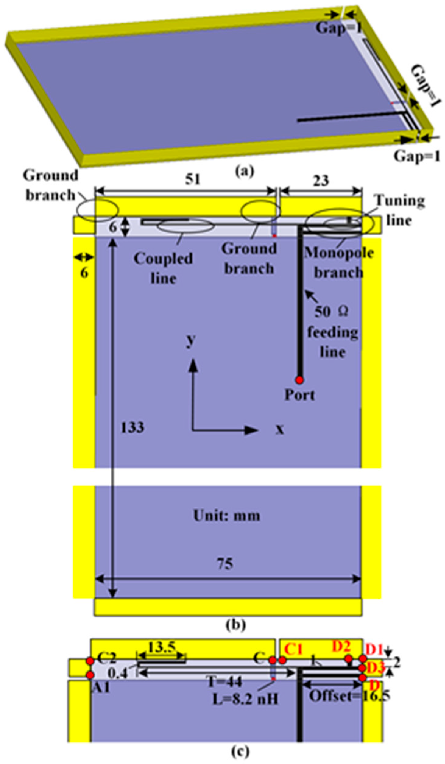
As shown in
Figure 1, the antenna proposed in this paper was mounted on a printed circuit board (PCB). The size of the PCB was 139 mm × 75 mm × 0.8 mm, the loss tangent was 0.02, and the relative permittivity was 4.4. The proposed antenna consisted of a coupled line, a ground branch, a monopole branch, and a tuning line. At the back of the PCB, a metal ground with a size of 133 mm × 75 mm, shown in gray, was printed. As shown in
Figure 1a, the metal frame with the height of 6 mm had three gaps (the widths of the gaps were all 1 mm). The U-shape metal frames with the sizes of 133 mm × 6 mm, 75 mm × 6 mm, and 133 mm × 6 mm (shown in yellow) were all connected to the ground edges.
As shown in
Figure 1b, the ground branch was the longer branch connected to the ground at the upper left of the PCB, and the monopole branch was the shorter branch at the upper right of the PCB. As shown in
Figure 1c, the ground branch consisted of a lumped inductance of 8.2 nH, a rectangle strip, and an L-shape folded strip, which was folded first at segment C–C2 and then at segment C2–A1, both along the z-axis direction. The monopole branch consisted of a rectangle strip printed on the front of the PCB and an L-shape folded strip, which was folded first at segment D–D1 and then at segment D1–C1, both along the z-axis direction. The above mentioned two L-shape folded strips were parts of the metal frame and located at the top edge of the PCB. The tuning line was a T-shape branch connected to the monopole branch at D2 and D3. Last, a 50-Ω feeding line (shown in black) was connected to the coupled line, the monopole branch, and the tuning line at the front of the PCB.
3. Antenna Analysis
To study the working mechanism of the proposed antenna, the functions of the coupled line, the ground branch, the monopole branch, and the tuning line were analyzed. The current distributions at the resonant frequencies are presented to better understand the working modes. The following simulated results were obtained using the software of the High Frequency Structure Simulator (HFSS) 15.0.
3.1. Analysis of the Main Structures
To study the functions of the main structures, the proposed antenna was formed as follows: First, only the coupled line is included (Ant 1); then, Ant 2 is formed by adding the ground branch to Ant 1; next, the monopole branch is added to Ant 2 to form Ant 3; finally, the proposed antenna is formed by adding the tuning line to Ant 3. The simulated S-parameters of Ant 1, Ant 2, Ant 3, and the proposed antenna are presented in
Figure 2.
From
Figure 2, we found that Ant 1 resonated at about 1.1 GHz, 2.9 GHz, and 4 GHz, but the match was not good at about 1.1 GHz. The resonant frequencies at about 1.1 GHz, 2.9 GHz, and 4 GHz were the 0.25, 0.75, and 1 wavelength modes of the coupled line, respectively. To realize the lower band, more modes needed to be introduced, so the ground branch was added to Ant 1, and then Ant 2 was formed. For Ant 2, a new resonant frequency at about 0.725 GHz, which is the 0.25 wavelength mode of the ground branch, appeared, and the desired lower band was nearly matched. The resonant frequency at about 1.1 GHz shifted to about 0.95 GHz. At the higher band, the resonant frequencies at about 2.9 GHz and 4 GHz shifted to about 2.7 GHz and 3.7 GHz, respectively. There were three resonant frequencies at about 2.2 GHz, 2.7 GHz, and 3.7 GHz. The new resonant frequency at about 2.2 GHz was the 0.75 wavelength mode of the ground branch according to the electronic length. To cover the whole higher band, new resonant frequencies needed to be added. Thus, the monopole branch was added to Ant 2, and Ant 3 was formed.
For Ant 3, the match at the lower band became much better and the desired lower band was obtained. At the higher band, there was a new resonant frequency at about 1.4 GHz, which is the 0.25 wavelength mode of the monopole branch. The resonant frequency at about 2.7 GHz shifted to about 3 GHz. At last, the tuning line was added, and the proposed antenna was formed. At the lower band, the match and bandwidth had little change. At the higher band, the resonant frequency at about 1.4 GHz shifted to about 1.8 GHz. The resonant frequency at about 3 GHz split into two resonant frequencies at about 2.7 GHz and 3.1 GHz and the desired higher band was matched.
As a conclusion, the ground branch and the coupled line were used to obtain the lower band, the monopole branch was used to improve the match at the lower band and obtain the higher band, and the tuning line was used to improve the match at the higher band. The two resonant frequencies (0.725 and 0.95 GHz) at the lower band were produced by the 0.25 wavelength mode of the coupled line and the ground branch, respectively. The five resonant frequencies (1.8, 2.2, 2.7, 3.1, and 3.7 GHz) at the higher band were produced by the 0.25 wavelength of the monopole branch, the 0.75 wavelength mode of the ground branch, and the 0.75 and 1 wavelength modes of the coupled line, respectively. Thus, the proposed antenna was designed by using the folded branches, coupled feeding line, and the tuning line to excite multiple modes to cover multiple bands. The described method is a useful method to design a multi- or wide-band antenna.
3.2. Current Distributions
To further analyze the work principle of the proposed antenna, we simulated the current distributions at 0.725, 0.95, 1.8, 2.2, 2.7, 3.1, and 3.7 GHz. The results are shown in
Figure 3. At 0.725 GHz, the current mainly distributed at the ground branch and the coupled line, the current had a maximum value at A and a minimum value at A1; thus, the proposed antenna worked at the 0.25 wavelength mode of the ground branch at the section of AA1. At 0.95 GHz, the current had a maximum value at B and a minimum value at B1, thus the 0.25 wavelength mode of the coupled line was excited at the section of BB1. At 1.8 GHz, the current had a maximum value at C and a minimum value at C1 the 0.25 wavelength mode of the monopole branch was excited at the section of CC1. At 2.2 GHz, the current was maximum at A and minimum at A2 and A1, the 0.75 wavelength mode of the monopole branch was excited at the section of AA2A1. At 2.7 GHz, the current was maximum at B and minimum at B1 and B2, thus the 0.75 wavelength mode of the coupled line was excited at the section of BB2B1. At 3.1 GHz, the current was maximum at D and minimum at B1 and B2, thus the 0.75 wavelength mode of the coupled line was excited at the section of DB2B1. At 3.7 GHz, the current was minimum at E, B3, and B1, thus the 1 wavelength mode of the coupled line was excited at the section of EB3B1.
In conclusion, the proposed antenna worked at the 0.25 wavelength modes of the ground branch, the coupled line, and the monopole branch, and the 0.75 and 1 wavelength modes of the coupled line. They are concurrent with the analysis of
Section 3.1.
3.3. Parameter Study
To further understand the proposed antenna, the effects of the value of the lumped inductance, the length of the coupled line, and the feeding place were analyzed. The parameters L, T, and Offset (as shown in
Figure 1c) are the value of the lumped inductance, the length of the coupled line, and the place of the feeding line, respectively. The influences of these parameters on the S-parameter are shown in
Figure 4,
Figure 5 and
Figure 6, respectively.
From
Figure 4, it can be seen that L had a big influence on the match at the lower band. When the value of L1 increased, the match at the lower band became worse. At the higher band, the match became better at about 2.2 GHz, but became worse at about 2.7 GHz. Considering the bandwidth and the match, L = 8.2 nH was chosen.
As shown in
Figure 5, when T became bigger, at the lower band, the match became worse at about 0.75 GHz, but became better at about 0.95 GHz. At the higher band, the resonant frequencies at about 2.1 and 3.7 GHz became smaller whereas the match became better. Trading off the match and the bandwidth, T = 45.5 mm was chosen.
From
Figure 6, one can see that the feeding place influenced the S11, not only at the lower band but also at the higher band. When the value of Offset became larger, at the lower band, the match became better at about 0.75 GHz, but became worse at about 0.95 GHz. At the higher band, the match became worse at about 2.1, 2.7, and 3.5 GHz. The resonant frequency became smaller at about 3.1 GHz, but became larger at 3.7 GHz. Considering the match and the bandwidth, Offset = 16.5 mm was chosen.
5. Conclusions
This paper proposes a nine-band metal frame antenna with a size of 75 mm × 6 mm × 6 mm for 4G and 5G mobile phones. It consists of a coupled line, a ground branch, a monopole branch, and a tuning line. The novelty of the proposed antenna is that more modes are excited and work together to obtain multiple working bands, by using the coupled line and the folded branches with the help of the tuning line, and then nine bands are obtained under the conditions of a 6 mm, only, ground clearance and a metal frame environment. The measured −6 dB impedance bandwidths are 345 MHz (0.685–1.03 GHz) at the lower band and 2160 MHz (1.67–3.83 GHz) at the higher band. The LTE700, GSM850, GSM900, DCS, PCS, UMTS, LTE2300, and LTE2500 bands for 2G, 3G, 4G, and the 3.5 GHz band that is possible for 5G are covered. The measured efficiencies are 51–66% at the lower band, and 49–75% at the higher band.


