Abstract
This paper reports a field-programmable gate array (FPGA) design of compressed sensing (CS) using the orthogonal matching pursuit (OMP) algorithm. While solving the least-squares (LS) problem in the OMP algorithm, the complexity of the matrix inversion operation at every loop is reduced by the proposed partitioned inversion that utilizes the inversion result in the previous iteration. By the proposed matrix (n × n) inversion method inside the OMP, the number of operations is reduced down from O(n3) to O(n2). The OMP algorithm is implemented with a Xilinx Kintex UltraScale. The architecture with the proposed partitioned inversion involves 722 less DSP48E compared with the conventional method. It operates with a sample period of 4 ns, signal reconstruction time of 27 μs, and peak signal to noise ratio (PSNR) of 30.26 dB.
1. Introduction
The compressed sensing (CS) can effectively acquire and reconstruct sparse signals with significantly less samples than that required from the Nyquist–Shannon sampling theorem [1]. The reconstruction process in CS finds the best solution to an underdetermined system, with a linear equation of the form y = x, where we know the measurement matrix, , that model the sampling system and the measurement vector, y, while the original signal, x, remains to be determined.
Various algorithms have been proposed to reconstruct the signal x from the compressively sensed samples. Generally, two algorithms, the greedy pursuit [2,3] and the convex relaxation [4,5], are mainly selected for sparse signal reconstruction. The greedy pursuit is a more useful CS algorithm than the convex relaxation, because it uses floating point operations [6]. Orthogonal matching pursuit (OMP) is one of the representative greedy-type solvers for CS, which finds columns of the measurement matrix, , that are mostly correlated with the current estimate, , of the original signal for m-iterations, where m is the sparse level, and updates an advanced signal estimate from a least-squares (LS) method.
In OMP, one of the major problems in the LS step is the matrix inversion, because it results in a high computational complexity per iteration [7]. Several inversion methods for the OMP algorithm have been proposed, such as the QR decomposition [8] and Cholesky-based factorization [7,9], to improve the computation efficiency of the matrix inversion. However, OMP that utilizes the partitioned inversion has not been presented, to the best of authors’ knowledge, because the conventional partitioned inversion may result in a low efficiency for computation. Thus, we propose a novel matrix inversion with a better computational efficiency, based on the incremental computation of the partitioned inversion targeting the OMP.
In this paper, we utilize three properties of the input matrix for the inversion in each OMP iteration, namely: conjugate symmetry, positive definiteness, and overlapped regions. It is found that the properties reduce the computation complexity by re-utilizing the computation results obtained in the previous OMP iteration. In terms of the comparison of the computation complexity, the novel partitioned inversion method improves the complexity over the conventional Cholesky-based inversion and the conventional partitioned inversion based on our derived equations. In addition, multiple measurement vectors (MMV) are applied to the OMP algorithm to improve the sparse signal recovery compared to the single measurement vector (SMV) method, and it is called simultaneous OMP (SOMP) [10]. Lastly, we have implemented SOMP with the proposed matrix inversion method in the field-programmable gate array (FPGA) and measured the running time. The experiments show that the total hardware utilization is significantly reduced compared with the conventional partitioned inversion, and the reconstruction time is 27 μs. Section 2 introduces the overview of the SOMP algorithm, and the conditions of the input matrix in LS problem are described in Section 3. Section 4 proposes the novel partitioned inversion, and the experimental results are presented in Section 5. Finally, Section 6 provides a conclusion.
2. Overview of SOMP Algorithm
2.1. Description of SOMP Algorithm
In the SOMP, the linear equation is defined by the following:
where y ℝM×L, ℝM×N, and ℝN×L. The SOMP process given in Algorithm 1 [11] consists of the optimization problem (1 and 2) and the LS problem (3 and 4). For this process, the residue, (when i = 1) is initially set to y. During the ith iteration, the optimization problem chooses one of the columns of , which is strongly correlated to the residue of y, and then searches the position, k, of this column. The is the sub-matrix including the column according to the k, and is updated by summing with the previous sub-matrix. The LS problem removes the contributed column for the new estimate, , and then computes a new residue, r. Finally, when the m-iteration is achieved, the final estimate of the original signal is computed.
| Algorithm 1. Simultaneous orthogonal matching pursuit (SOMP). |
| Input: •ℝM×N: The measurement matrix • y ℝM×L: The multiple measurement vector Output: • ℝN×L: The estimate of original signal Variable: • m: The sparsity level of original signal x • r ℝM×L: The residue Initialize: , For ith iteration: 1. , where , and k is an index 2. 3. 4. Repeat process until i = m to generate the final estimate of the . |
2.2. Least Square (LS) Problem
In the SOMP algorithm, the recovered signal, , gradually becomes similar to the input signal, x, with more iterations, and the equation for the new residue in the LS problem is as follows:
In Equation (2), the computation complexity reduction of the inverse of the input matrix, , is a challenge in the OMP algorithm.
3. Conditions of the Input Matrix in LS Problem
The input matrix, , in the LS problem presents the various conditions, as below. The is always symmetric, as follows:
which is a positive definite, and is expressed by the following:
Equation (4) indicates that the eigenvalue, , is always greater than zero. That is, (=) satisfies the positive definite condition, while following the characteristics: (1) exsits, (2) for all t in diag (, , , , ) and (3) principle sub-matrices, are also positive definite.
In step 2 of Algorithm 1, is added one column per loop, and then the input matrix, , is determined. As the loop progresses, the next includes the matrix for the previous loop, as shown in Table 1. For example, is an expanded matrix of of the previous iteration. Thus, is divided into a previously obtained part and a newly added part.

Table 1.
Overlapped region in input matrix.
4. Proposed Partitioned Inversion
By leveraging the properties of the input matrix as examined in Section 3, we propose a novel partitioned inversion method after explaining the conventional partitioned inversion in this section.
4.1. Conventional Partitioned Inversion
The conventional partitioned inversion is a method to obtain the inverse matrix by dividing the input matrix into four parts. This inversion is robust against noise, because of a low number of conditions, and operates using lower parts of the input matrix in symmetric and positive definite (SPD) characteristics. The step for the inverse matrix of the conventional way is introduced in the left column of in Table 2. However, as the matrix size increases, the number of computations grows significantly.

Table 2.
Conventional partitioned inversion versus proposed partitioned inversion.
4.2. Proposed Partitioned Inversion
In order to reduce the inversion computational complexity, the following relationships are obtained by utilizing the input matrix properties presented in Section 3.
As the input matrix, , is symmetric, the constituent matrices of the input matrix (A, B, C, and D) satisfy Equation (5), which is used in the following optimization processes.
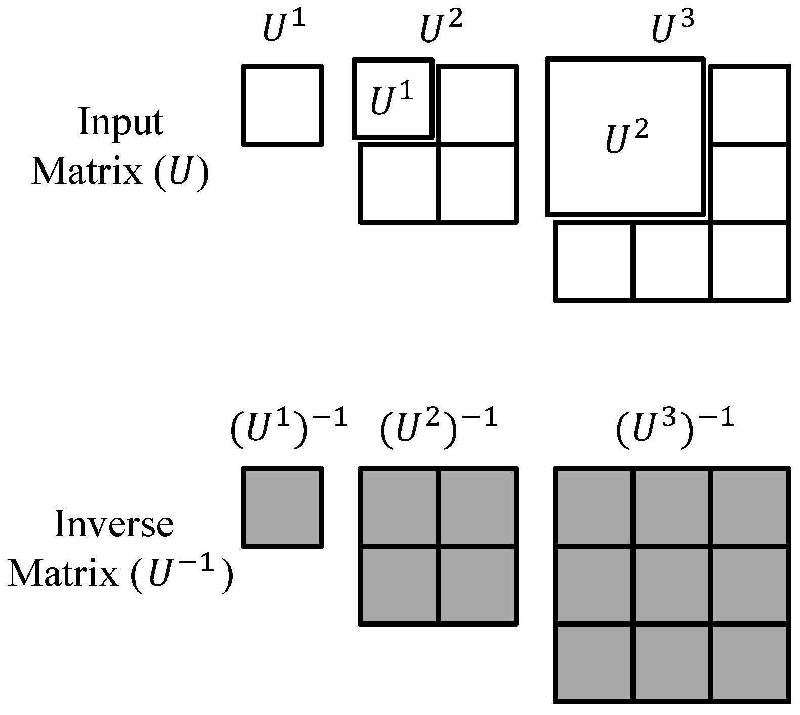
Step 1 in the conventional partitioned inversion in Table 2 is eliminated by the following observation. In ith OMP iteration, is portioned into four sub-matrixes containing , as shown in Figure 1. Unlike the conventional partitioned inversion, this step contains , of which the inversion is already available in the previous OMP iteration. Therefore, step 1 is unnecessary, by utilizing , shown in gray in Figure 1.
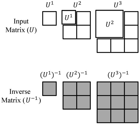
Figure 1.
Reduction of computation complexity by copying the inverse matrix from previous iteration.
Steps 2 and 3 are decreased down to a single step based on Equation (5).
Steps 7 and 8 are also further simplified by Equation (5), as below.
From Equations (5)–(8), the number of steps in the inversion process is reduced from 10 to 7, as shown in Table 2.
4.3. Computational Complexity for Proposed Partitioned Inversion
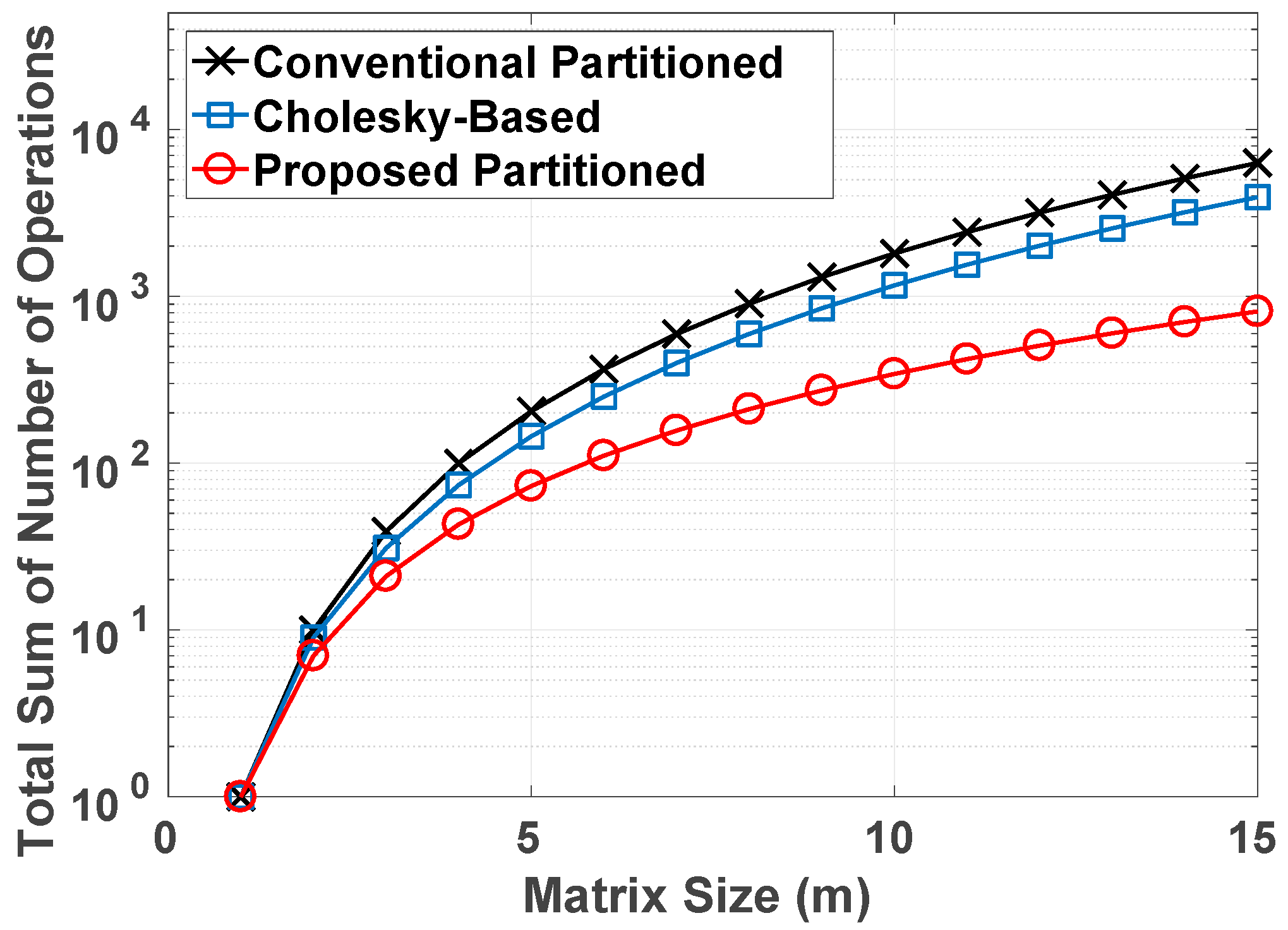
Table 3 shows the complexity comparison between three inversion techniques. The Cholesky-based and conventional partitioned inversion continually calculates the inversion of the size-increased matrix per iteration, whereas our inversion method computes the extra sub-matrices except for prior iteration calculation. Accordingly, the proposed method improves the computational complexity for multiplication, addition/subtraction, and division, depending on the input matrix size, where the matrix size increases from 1 × 1 to m × m per loop. To visualize the improved complexity, we executed a MATLAB (2013b, The MathWorks, Natick, MA, USA) simulation for a computational comparison of the total number between the Cholesky-based inversion, conventional partitioned inversion, and proposed partitioned, depending on the matrix size (m × m), as depicted in Figure 2.

Table 3.
Computation Complexity Comparison of input matrix inversion (for m × m matrix and a single supporter system).
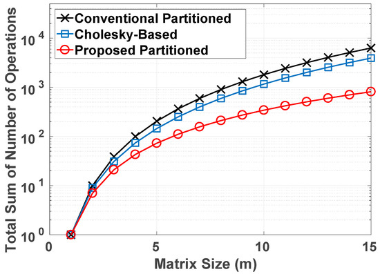
Figure 2.
The total sum of number of operations for the Cholesky-based inversion, conventional partitioned inversion, and proposed partitioned inversion, depending on matrix size (m × m).
4.4. Proposed Partitioned Inversion for Multiple Supporter System
Computation complexity functions in Table 3 are only applied to a single supporter system; however, our inversion method is also used in the multiple supporter system, and the complexity equations are changed as Equations (9)–(11).
- Multiplication:
- Add/sub:
- Division:where n is the number of the supporter. Although the computation complexity becomes larger as n increases, the proposed inversion method can be applied to the multiple supporter system.
4.5. SOMP Structure with the Proposed Partitioned Inversion
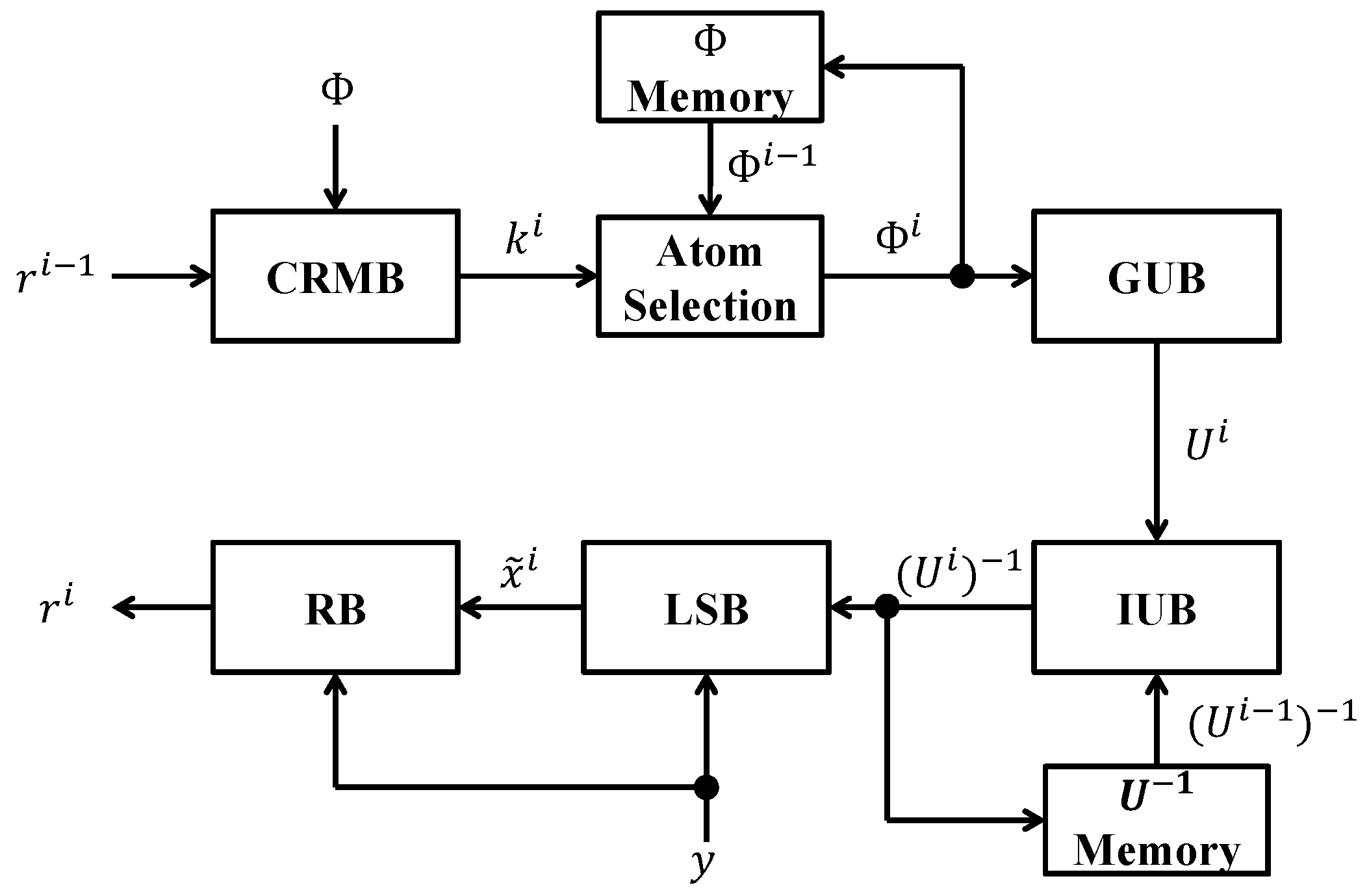
The SOMP structure with the proposed partitioned inversion is organized as shown in Figure 3. The correlation matching block (CRMB) finds the location, k, of the most correlated column of the measurement matrix, , and is updated by the summing of (which is saved by the memory block at the previous iteration) and . Generating the block (GUB) identifies the row of the measurement matrix corresponding to k, and generates the matrix by the inner-product. The inverse of is generated by the inversion block (IUB), which is stored in the memory block, and the memory offers the previous calculated inverse matrix of . Thus, IUB can reduce the computational complexity by using the previously computed inverse matrix of . The least square block (LSB) calculates the estimate, , of the original signal, and the residual, , is generated by the residual block (RB). Finally, the final estimate signal is obtained by the system at m-iteration.
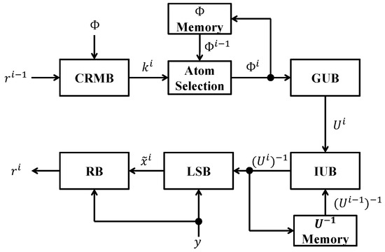
Figure 3.
Simultaneous orthogonal matching pursuit (SOMP) structure with the proposed partitioned inversion.
5. Experiment Results
5.1. FPGA Implementation Approach
In our experiment, the Xilinx Kintex UltraScale board and the XCKU115-FLVA2104-2-I chipset was used to demonstrate the proposed inverse matrix and the operation of the entire SOMP algorithm. The board is advantageous to the design of a large algorithm, because it has a large number of DSP slices.
The high-level synthesis (HLS) tool provided by Xilinx for the FPGA design offers many advantages, namely: (1) arbitrary precision data type, math, IP, linear algebra, and many other libraries; (2) the register-transfer level (RTL) can be extracted automatically, and RTL verification is easy, because of the provided co-simulation; (3) as C synthesis provides design resources, such as clock, area, and I/O port description, a user can easily change the design according to their intention; (4) it enables high-performance hardware design with little hardware knowledge, because it facilitates its utilization for the IP module in other design tools, such as the system generator. By leveraging these advantages, we convert the C/C++ code into the hardware description language (HDL), such as Verilog, which is subsequently synthesized to the gate level for the optimization of our design architecture.
Our device is based on a 16- and 32-bit fixed-point complex operation. Most of the calculations were performed with 16-bit, but the partitioned inversion process relies on 32-bit, because the divide operation requires more precise computation.
The parameters used in our experiment are as follows. The number of physical channels is four and the dimensions of the measurement matrix (M × N) are 32 and 128, respectively. The channel reuse factor is 8, MMV extension is 16, Nyquist bandwidth is 4 GHz, sampling frequency is 250 MHz, Fp is 31.25 MHz, and FFT-point is 128.
5.2. Additional Optimisation in FPGA Implementation
In the SOMP algorithm, a large matrix inner product is needed. To express the matrix inner product in the code, we require three for loops. We apply a pipeline to the second for loop to perform real-time signal reconstruction. Although the number of DSP increases in proportion to the number of the innermost for loop, the latency is greatly reduced, because the calculation can be parallel.
Most of the operations that occurred inside it are complex types, and is thus accompanied by an increase in the computational complexity. Even if the partitioned inversion device requires complex division, it can be replaced by two real divisions because the denominator is always a positive real number.
5.3. SOMP Hardware Utilization
Various components are required for hardware realization of the SOMP algorithm. The block ram (BRAM) effectively stores the vectors and matrices, namely: the measurement vector, y, measurement matrix, , and residue, r. The DSP is the pre-built multiply-accumulate (MAC) circuit in the FPGA and is an essential hardware, because it quickly performs the multiplication and addition/subtraction operations. Flip-flop (FF) is the shift register used to synchronize the logic. The total hardware utilization for the proposed partitioned inversion is reduced compared to the conventional partitioned inversion, as shown in Table 4. However, only the BRAM for our inversion method is increased compared to the conventional approach because both the matrix and previous matrix must be stored simultaneously.

Table 4.
OMP hardware utilization comparison between conventional partitioned inversion and proposed partitioned inversion. BRAM—block ram; FF—flip-flop.
5.4. Signal Reconstruction
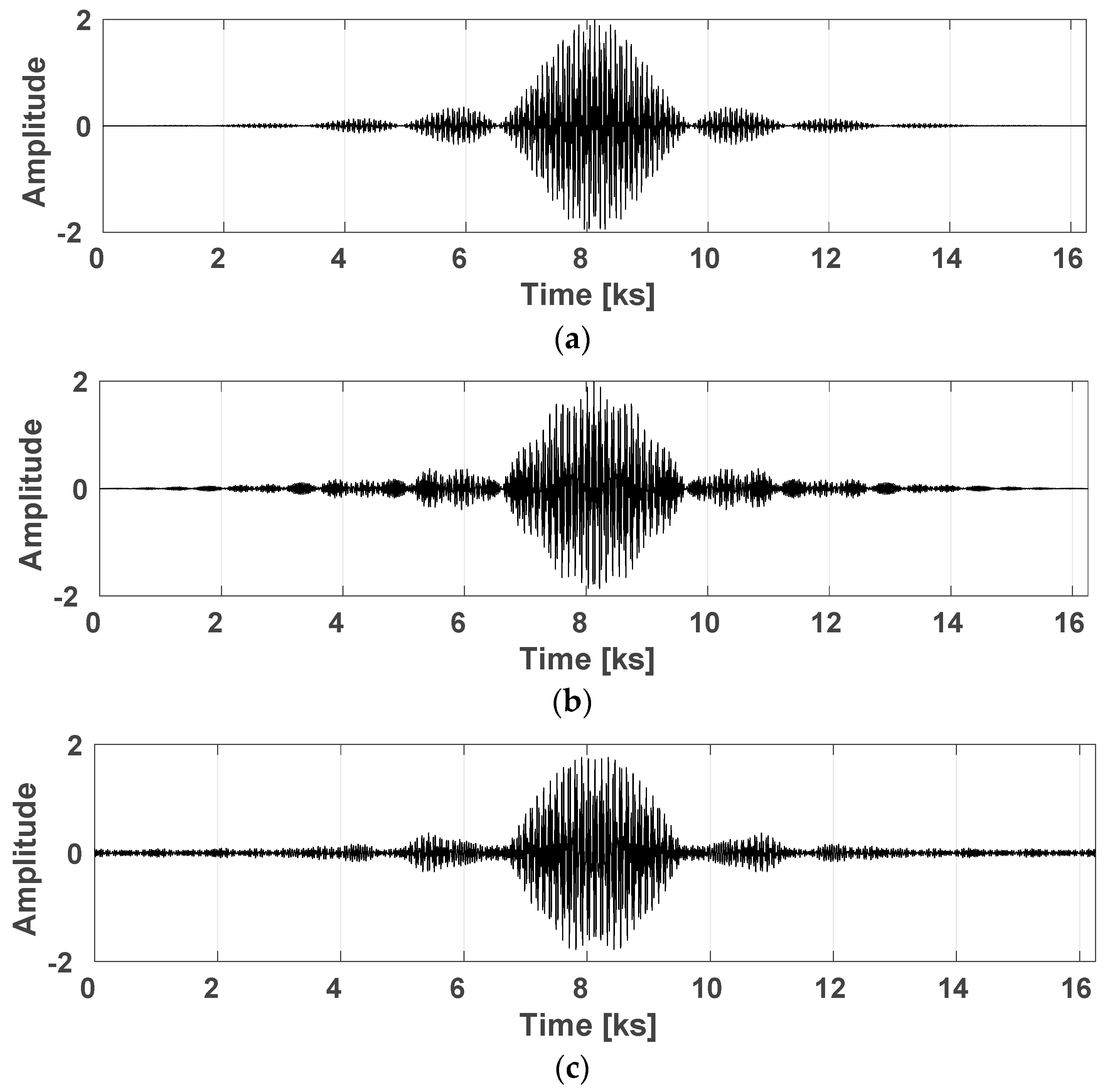
We executed the MATLAB simulation and HLS to validate the recovered signal from the input sparse signal, and data precision is converted from 16(0.12) to 32(0.24) bits, where the data format p(.f) with the precision (p) and factional bits (f). Figure 4a presents the input sparse signal, which is mixed by the random carrier signals. The signal is well reconstructed by both the simulation and HLS, as shown in Figure 4b,c, respectively.
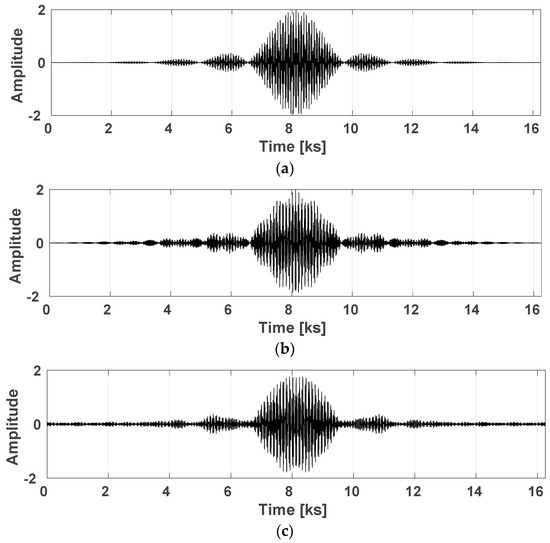
Figure 4.
Reconstruction of the sparse modulated by random carrier frequencies for (a) input signal, (b) reconstruction signal by MATLAB, and (c) reconstruction signal by high-level synthesis (HLS) for 16- and 32-bit data precision.
From our experiment, we obtained the peak signal to noise ratio (PSNR) for an objective evaluation [7], where PSNR is as follows:
where MAX is the maximum possible value of the signal x, N is the total number of samples, is the sample value at i in the reconstructed signal, and is the sample value at i in the original signal. The PSNR of our SOMP structure was determined to be 30.26 dB for 16- and 32-bit data precision.
5.5. Performance Comparison
Table 5 provides a comparison of the performance of existing sparse signal recovery algorithm devices. Although the other works summarized in Table 5 focus on the OMP algorithm rather than the inversion method, an objective comparison is required to highlight our proposed inversion method. For this reason, we selected papers with the identical measurement matrix size (32 × 128), while applying the different inversion methods (i.e., QR decomposition-based and Cholesky-based inversions). Although our work uses a higher clock frequency than other works in Table 5, our reconstruction time is sufficiently fast with larger sparsity than in the literature [7,12,13].

Table 5.
Performance comparison for the 32 × 128 measurement matrix size.
6. Conclusions
The SOMP algorithm generally results in a high computational complexity for the LS problem, because of a very large inner product. In addition, the SMV model causes an increase of this complexity. To reduce the complexity, we have proposed the SOMP algorithm for the MMV models, while applying a novel partitioned inversion that omits the recalculation for the inversion of the input matrix at the previous loop. Accordingly, our proposed inversion method restores a signal with less hardware compared with the conventional partitioned inversion techniques. By using the Kintex UltraScale board and HLS, we verified the signal reconstruction with a high PSNR and obtained a fast reconstruction time. Therefore, in comparison with the conventional partitioned inversion and Cholesky-based factorization, our proposed inversion is suitable to apply the diverse applications requiring the high-level restoration with less hardware, such as bio-signals, bio-medical imaging, and radar.
Author Contributions
Conceptualization, M.L.; Formal analysis, U.Y. and G.S.; Investigation, S.K. and J.J.; Methodology, U.Y.; Project administration, J.K.; Supervision, H.-N.L. and M.L.; Validation, J.J.; Visualization, S.K.; Writing—original draft, S.K.
Funding
This work was supported by a grant-in-aid of HANWHA SYSTEMS.
Conflicts of Interest
The authors declare no conflict of interest.
References
- Candes, E.; Wakin, M. An introduction to compressive sampling. IEEE Signal Process. Mag. 2008, 25, 21–30. [Google Scholar] [CrossRef]
- Pati, Y.; Rezaiifar, R.; Krishnaprasad, P. Orthogonal matching pursuit: Recursive function approximation with applications to wavelet decomposition. In Proceedings of the IEEE Record of The Twenty-Seventh Asilomar Conference on Signals, Systems, and Computers, Pacific Grove, CA, USA, 1–3 November 1993; pp. 40–44. [Google Scholar]
- Tropp, J.; Gilbert, A. Signal recovery from random measurements via orthogonal matching pursuit. IEEE Trans. Inf. Theory 2007, 53, 4655–4666. [Google Scholar] [CrossRef]
- Chen, S.; Donoho, D.; Saunders, M. Atomic decomposition by basis pursuit. SIAM Rev. 2001, 43, 129–159. [Google Scholar] [CrossRef]
- Khan, I.; Singh, M.; Singh, D. Compressive sensing-based sparsity adaptive channel estimation for 5G massive MIMO systems. Appl. Sci. 2018, 8, 2076–3417. [Google Scholar] [CrossRef]
- Sahoo, S.; Makur, A. Signal recovery from random measurements via extended orthogonal matching pursuit. IEEE Trans. Signal Process. 2015, 63, 2572–2581. [Google Scholar] [CrossRef]
- Rabah, H.; Amira, H.; Mohanty, B.; Almaadeed, S.; Meher, P. FPGA implementation of orthogonal matching pursuit for compressive sensing reconstruction. IEEE Trans. Very Large Scale Integr. Syst. 2015, 23, 2209–2220. [Google Scholar] [CrossRef]
- Bai, L.; Maechler, P.; Muehlberghuber, M.; Kaeslin, H. High-speed compressed sensing reconstruction on FPGA using OMP and AMP. In Proceedings of the 19th IEEE International Conference on Electronics, Circuits, and Systems (ICECS), Seville, Spain, 9–12 December 2012; pp. 53–56. [Google Scholar]
- Blache, P.; Rabah, H.; Amira, A. High level prototyping and FPGA implementation of the orthogonal matching pursuit algorithm. In Proceedings of the 11th IEEE International Conference on Information Science, Signal Processing and their Applications (ISSPA), Montreal, QC, Canada, 2–5 July 2012; pp. 1336–1340. [Google Scholar]
- Tropp, J.; Gilbert, A.; Strauss, M. Algorithms for simultaneous sparse approximation. Part 1: Greedy pursuit. Signal Process. 2006, 86, 572–588. [Google Scholar] [CrossRef]
- Determe, J.; Louveaux, J.; Jacques, L.; Horlin, F. On the exact recovery condition of simultaneous orthogonal matching pursuit. IEEE Signal Process. Lett. 2016, 23, 164–168. [Google Scholar] [CrossRef]
- Quan, Y.; Li, Y.; Gao, X.; Xing, M. FPGA implementation of realtime compressive sensing with partial Fourier dictionary. Int. J. Antennas Propag. 2016, 2016, 1671687. [Google Scholar] [CrossRef]
- Septimus, A.; Steinberg, R. Compressive sampling hardware reconstruction. In Proceedings of the IEEE International Symposium on Circuits and Systems (ISCAS), Paris, France, 30 May–2 June 2010; pp. 3316–3319. [Google Scholar]
© 2018 by the authors. Licensee MDPI, Basel, Switzerland. This article is an open access article distributed under the terms and conditions of the Creative Commons Attribution (CC BY) license (http://creativecommons.org/licenses/by/4.0/).

