Multi-Backup Beams for Instantaneous Link Recovery in mmWave Communications


Department of Electrical Engineering, King Faisal University, Hofuf 31982, Saudi Arabia
Electronics 2019, 8(10), 1145; https://doi.org/10.3390/electronics8101145
Submission received: 6 September 2019
/
Revised: 6 October 2019
/
Accepted: 6 October 2019
/
Published: 10 October 2019
(This article belongs to the Special Issue Millimeter-Wave (mmWave) Communications)
Abstract
:In this paper, a novel link recover scheme is proposed for standalone (SA) millimeter wave communications. Once the main beam between the base station (BS) and the mobile station (MS) is blocked, then a bundle-beam is radiated that covers the spatial direction of the blocked beam. These beams are generated from an analog beamformer design that is composed of parallel adjacent antenna arrays to radiate multiple simultaneous beams, thus creating an analog beamformer of multiple beams. The proposed recovery scheme features instantaneous recovery times, without the need for beam scanning to search for alternative beam directions. Hence, the scheme features reduced recovery times and latencies, as opposed to existing methods.
1. Introduction
Millimeter wave (mmWave) frequencies represents a major component of standalone (SA) 5G networks for high data rates support in enhanced mobile broadband (eMBB). One key advantage here is the contiguous available spectrum at these bands. However, the aggregated path losses impose the use of beamforming techniques to achieve higher link gains. The use of directional transmission and reception here (absence of omni-directional modes), requires the base station (BS) and mobile station (MS) to scan over all spatial directions to determine the best beamforming and combining vectors that yield the highest received signal level [1]. Consequently, this creates high computational complexity and prolonged access times, i.e., long control-plane latencies. This, in turn, contradicts with the International Mobile Telecommunications (IMT) framework requirements that define 10 milliseconds (ms) latency levels for eMBB in 5G systems [2]. Therefore, initial beam access schemes need to attain reduced times to achieve short control plane latencies. Consequently, beam access and adaptation arise as challenging problems in mmWave systems. Once initial access procedures are performed, the BS and MS need to maintain robust link adaptation when signal levels drop due to mobility and blockage effects. In particular, mmWave links are highly vulnerable to obstacles in the propagation paths between the MS and BS, which degrades signal levels and triggers link blockage [3]. This deficiency is more likely to occur when transmitting at narrow beams, i.e., short coherence times and low-channel ranks. Therefore, efficient beam recovery schemes are required to overcome link blockages, maintain communication sessions without drops, and reduce requirements for repeated beam access procedures.
In light of the above, this paper presents a novel beam recovery scheme to overcome link blockage effects and provides instantaneous beam recovery times, without the requirements for beam scanning. The scheme develops a bundle of simultaneously radiated beams that compensate for the blocked beam using an analog beamforming architecture. Namely, when blockage effects are introduced, the link is transiting from a line-of-sight (LoS) to a non-line-of-sight (NLoS) operation, which decays the signal quality. Conventional schemes require the beam to find alternative spatial directions by performing beam scanning. Meanwhile, the proposed scheme radiates the beam-bundle after blockage occurs, i.e., acting as backup beams. This, in turn, eliminates the need for beam scanning since the bundle radiates in different directions, hence resulting in signal aggregation at the receiver.
This paper is organized as follows: Firstly, Section 2 presents a survey on recent studies on beam recovery methods. Then, a proposed scheme is presented by first proposing the novel beamforming model in Section 3, along with the channel and signal models. This is followed by the bundle-beam recovery scheme in Section 4. Then, the performance evaluation is presented in Section 5, and finally, conclusions and future directions are discussed in Section 6.
2. Related Work
Multiple studies have investigated the beam recovery problem in mmWave communications. The work in [4,5] used hierarchical codebook-based procedures that restart the beam access search if a blockage effect is triggered. The authors in [6] presented a new beam aggregation method for fast beam recovery. The method utilized two beams to collectively add signal powers from the same direction. Moreover, an equal gain combining (EGC) scheme was presented in [7] that also combines multiple signals, which are received from the secondary and tertiary best directions, in order to overcome the signal losses caused by blockage at the main beam. Note that the aforementioned schemes are limited to low blockage parameters (obstacles of low density). Therefore, these schemes can yield unreliable links in dense scenarios.
Additionally, authors in [8] computed the signal level at the neighboring beam to the blocked direction affiliated with the main beam. Here the BS and MS are compelled to perform beam scanning, which features an increased number of measurements at the neighboring directions. In turn, this results in prolonged recovery times and vulnerability to communication sessions-drop. Moreover, a relay node method was presented in [9] that performs a handover decision when the direct link at the main beam is not recovered within a threshold time period. However, this scheme works only if at least triangulation geometry is available in the MS proximity. The work in [10] proposed a reactive beam recovery method, in which the MS exploits the microwave band to identify a back-up direction, in order to recover links from blockage without requirements for handover procedures. Note that the latter scheme is dependent on sub-6GHz microwave frequencies, which impedes the realization of SA mmWave networks.
3. System Model
3.1. Beamforming Design at the MS
Consider a MS equipped with an analog beamformer that is composed of parallel uniform linear arrays (ULA), where each ULA radiates a single beam, i.e., forming simultaneous multiple beams radiation in different directions. Each antenna is connected to a single analog phase shifter to provide continuous scanning capabilities (as opposed to step scanning in digital phase shifters). The ULAs are then connected to a single RF chain, as shown in Figure 1. Consider the design details.
In this paper, a novel multi-beam parallel array model is proposed at the MS. Hence, consider a MS equipped with a group of r = 1, 2, …, R parallel arrays, each composed of n = 1, 2, …, co-polarized antenna elements arranged in a linear geometric setting, i.e., forming one-dimensional radiation (1D). The elements are uniformly oriented with equi-spacing, i.e., , where λ represents the mmWave wavelength, , c is the speed of light, and is the carrier frequency. This spacing value is chosen so that grating lobes and pattern blindness are avoided, as well as to ensure there are minimal mutual coupling effects. Thus, it satisfies the formula d < , where the variable is the observation angle from array r at the MS in azimuth direction.
The maximum radiation pattern for the array points along scanning directions, for an even number of elements at any spatial direction is expressed by the closed-form normalized array response vector at each array r at the MS; which, in turn, is represented by the periodic array factor (AF), . This is expressed as
where the variable denotes the amplitude excitation for the n-th antenna element, represents the wave number, and symbolizes the relative progressive phase shift between the interconnected antenna elements at array r at the MS. Note that is a compact form that represents the array phase function at the MS with a visible region that varies between . Moreover, the half-power beamwidth (HPBW) at the broadside and scanning directions, i.e., , is expressed as [11]
whereas the HPBW at the endfire direction is computed as [12],
One important remark here, is that the spatial footprint of the array increases proportionally to a broadening factor of , for directions scanned off the broadside. Moreover, the array gain is gauged by , where is the gain for a single antenna element. For example, microstrip rectangular patch antennas are widely chosen for mmWave transceivers, and they provide a gain range of 5–7 dBi [13,14].
Each antenna array is fed in parallel by an array of P phase shifters, in particular, quadrature varactor-loaded transmission-line phase shifters. Note that the total number of phase shifters is equal to the number of antennas. Varactor phase shifters are chosen here due to their high shifting times (in μs), low power requirement, reduced loss rates, and capability to continuously adjust and control the [0, 2π] spatial plane using a single control voltage unit. The phase shifters are then connected to a single RF chain. Overall, this structure formulates an analog beamfomer composed of multiple radiated beams that carry the same modulated data. The benefit of using an analog beamformer here is to reduce the power consumption levels associated with the RF chains, as in the case of digital and hybrid architectures. Since a single RF chain is used at the MS, the orthogonal beam coding technique is adopted here. Namely, the weights of the antenna elements are modified by a unique set of codes to produce unique beams of distinguished signals. The orthogonal codes here create distinguishable spatial signatures for each beam-bundle, and thereby can identify the exact direction of the highest received signal in the bundle-beam from that particular direction.
Hence, this work exploits orthogonal Hamming codewords, , i.e., where e is the codeword length, and is the Hamming distance between successive codewords. Additionally, each codeword is scaled by the control signals, z, and features codebits, where is the total number of codebits. Consider the following codewords developed for a single bundle-beam, represented as:
These codewords feature zero cross-correlation, which yields in orthogonal beams in the bundle, hence receiving distinguishable signals in the directions of the beams [15,16]. Here, each codebit in the Hamming codeword is applied to the weight of a single antenna, where the number of codebits is equal to the number of antennas in the parallel array r. The codebit is either “1” or “−1”. If it is “1”, then the weight of the antenna remains the same, i.e., same amplitude and phase. Meanwhile, if the codeword is “−1”, then the conjugate is applied to the weight, i.e., keeping the same amplitude and rotating the phase by π.
These codes are reciprocal at the MS and BS. Therefore, when a signal is received at the BS, it is basically receiving one codeword. Namely, it multiplies the received codeword (appearing in the weights of the antennas) by all the four codewords, in order to retrieve the unique codeword and its affiliated beam in the bundle. As a result, the BS now identifies the directions with the highest signal level.
3.2. Digital Beamformer at the BS
Digital beamforming is adopted at the BS due to the abundant power input levels, and the necessity to provide multi-user connectivity. The beamformer architecture shown in Figure 2 is based upon a uniform circular array (UCA) with an identical radiation pattern of symmetric beamwidth in all spatial directions (no beam broadening at endfire direction), i.e., providing similar signal levels to MSs at different locations, with high directivities. The UCA here also features reduced sidelobe levels (SLL), and it eliminates the need for back-to-back arrays, as the case in the 1D ULA. Hence, consider a BS equipped with a UCA composed of total number of antenna elements, which are uniformly spaced on the x–y plane along radius, a, in a circular geometric setting. Now each antenna, , is also connected to an analog phase shifter to provide continuous beam scanning. This structure is connected to a group of RF chains , where the total number of RF chains is equal to the number of antennas. Overall, this setting results in a single beam radiated from each antenna, i.e., represented by the beamforming vector, , ; where is the beamforming matrix that represents the beam-bundle at the BS, , such that , where and denote, in order, the beamforming matrices at the baseband and analog stages, i.e., and =. Here, each vector carries unique modulated data that can be utilized for multi-users, or it supports a single datum to support MS with a beam-bundle when blockage occurs. This vector is gauged by the AF for the UCA, i.e.,
where the angles and represent the directions along the y- and x- axes, is the angular position of the n-th antenna, where . Moreover, the variables , v and in Equation (5) symbolizes the amplitude of the n-th antenna, the wave number, and the maximum radiation principal at the BS, evaluated as
3.3. Signal Model
Consider that MS and BS entities operate in LoS settings in urban outdoor environments composed of various objects in the proximity of the MS. In addition, assume a full-duplex division duplexing (FDD) channel of reciprocal channel state information (CSI) at both entities. Then, the downlink (DL) received signal profile at the MS, , is expressed as
where , H, z, and w denote in order the transmitted signal power, the power complex channel, the reference control signal, and the additive white Gaussian noise (AWGN), i.e., , where is the noise variance.
3.4. Channel Model
The geometric channel model, H, is adopted here due to the scattering nature of mmWave propagation. This is highly attributed to the large obstacle dimensions, as compared to the propagating wavelength at these bands. Consequently, this yields in reduced scattering profile, and hence results in poor scattering signal profile of a low number of rays, i.e., Poisson distribution. In turn, this results in high dependence on the geometry of the objects in the propagation link. This model is expressed as [17]
where the variables , and represent the blockage path loss model, and the gain of the l-th path. The signal profile here, is composed of L total number of paths that are observed in K total number of clusters, i.e., L K. These paths follow Rician-distribution that accounts for the LoS-to-NLoS plink transition caused by blockage effects. Namely, the path gain is modeled as , where is the power ratio between the dominant and other paths. Moreover, the beamforming and combining matrices, and (which also represent the response vectors), are evaluated using their far-field array factors (AF), as presented in the beamforming models.
3.5. Blockage Model
As mentioned earlier, the blockage path loss model, , accounts for LoS-to-NLoS link transition, when obstacles of different densities are present in the direct propagation link affiliated with the main beam. This model is formulated as [18]
where is an indicator function that specifies the link-blockage state, i.e., (x) = 1 iff x = 1, and it is set as (x) = 0 otherwise. Moreover, the variables and represent the path loss for the LoS and NLoS settings, respectively, expressed as [19],
where the variable d represents the distance between the BS and MS, is close-in reference distance, and and are the path loss exponents (PLE) for the LoS and NLoS settings, respectively. Moreover, the notations and ( denote the LoS and NLoS probabilities at the distance d. Here the probability is , where is the blockage parameter that accounts for obstacles of different dimensions and densities. Note that the higher the blockage parameter, the more blockage effects are caused to the link.
4. Recovery Procedure
Consider that MS and BS entities operate in a SA mmWave network in LoS settings of Rician scattering. During the initial access stage, an iterative random search is conducted over all spatial directions at the MS and B. This process returns the best beamforming and combining vectors (best pointing directions) that yield the highest received signal level, modeled as
where these best vectors present the maximum principal directions of the primary beams at the MS and BS, which are selected for the data-plane transmission. Now, once the session starts, the spectral efficiency can take various levels based on the link quality. First, when the link is in LoS, it features high link quality without obstacles (blockage parameter is zero), (x) = 0, as well as high instantaneous spectral efficiency, .
When the obstacles in the propagating path become present in the direct link associated with the main beam, it starts to exhibit instantaneous low spectral efficiency, and then blockage mode is in effect. Here the indicator function is set as (x) = 1, to indicate the LoS-to-NLoS transition. The blockage threshold is set based on the spectral efficient level, as
where SNR stands for the signal-to-noise ratio, the variable Ω denotes the loss factor (measured in dB), and represents the maximum spectral efficiency [20]. Note that the SNR is expressed as,
where Ψ, denotes the Boltzmann constant, is the operating temperature, is the channel bandwidth, and and are the array gains at the MS and BS respectively. , and , where is the gain for a single antenna element.
In light of the above, when the main beam is blocked, the MS and BS initiate the beam-bundle as the backup beams to compensate for the signal losses associated with the main beam, see Figure 3. Therefore, session drops are avoided. The MS here performs maximal ratio combining (MRC) to amplify high beam signals and attenuate weak beam signals, i.e.,
5. Performance Evaluation
The proposed recovery scheme is now evaluated using key metrics, in particular, the spectral efficiency, received signal profile, and recovery times. Consider Table 1 for the overall system settings.
5.1. Spectral Efficiency
Figure 4 shows the spectral efficiency for the proposed scheme at various blockage densities. The proposed scheme aims to enhance the spectral efficiency once beam blockage is in effect. Figure 4 shows the spectral efficiency for the proposed scheme versus conventional recovery methods that test neighboring beam directions or reset beam scanning procedures. When the direct propagation link between the MS and BS is free of obstacles (LoS operation), i.e., (x) = 0, high spectral efficiency is observed here. As a result, conventional methods and the proposed bundle-beam scheme yield high spectral efficiency. However, when obstacles start to appear in the propagation path of the primary beam, then the received signal level degrades, affecting capacity levels, and thereby reducing the spectral efficiency, as observed for the conventional schemes. For example, the work in [8] testing neighboring beams, requires beam scanning. Moreover, the beam aggregation method enhances the spectral efficiency if the density of the obstacles is low. However, this method results in a small number of scattering paths, attributed to the limited spatial coverage provided by the recovery narrow beams, which has a HPBW that is smaller than the dimensions of the obstacles. Meanwhile, the proposed scheme achieves high spectral efficiency if blockage parameters are dense. This is attributed to the wide spatial space covered by the back-up beam-bundle, which also yields in a high scattering profile that is leveraged using MRC.
5.2. Received Power Delay Profile
Figure 5 shows the received power profile in time domain for the proposed scheme as opposed to conventional schemes (i.e., testing adjacent beam directions) shown in Figure 6. The proposed recovery scheme yields a rich scattering profile due to the wide spatial coverage achieved by the instantaneous back-up beams, with HPBW that exceeds the obstacle’s dimensions, as well as enriching the reflections in the Rician path gains in the channel settings. For example, the proposed scheme exhibits 4–5 rays in 2–3 clusters when blockage is triggered, as opposed to 2–3 rays in 1–2 clusters for the neighboring beams testing and conventional codebook schemes. Furthermore, the recorded clusters here are received with power levels of −60 dBm, which relaxes the receiver sensitivity requirements. This is compared to −120 dBm and −140 dBm signal levels for the other schemes, which results in significant challenges in acquiring the signal, liming coverage ranges, as well as providing poor low channel capacity and impeding high channelization services for SA mmWave networks.
5.3. Beam Recovery Times
One major performance metric for beam recovery schemes is the beam recovery time. It is defined as the overall time period that is required to determine an alternative link direction once the direct link of the main beam is blocked. Namely, it is the period required to determine the new best beamforming and combining vectors, and their principal directions at the MS and BS. Figure 7 shows the recovery times at the MS (likewise for the BS, ). The proposed scheme achieves instantaneous recovery times without the requirement for beam scanning or resetting the access schemes when a link is blocked. The only time required here is the PSS transmission duration of the beam vectors (i.e., 200 μs). Overall, the scheme here promotes the feasibility of SA mmWaves with ultra-low recovery times, thereby realizing low latency requirements.
6. Conclusions
This paper presents a novel beam recovery scheme for standalone millimeter wave communications, without the reliance on sub 6 GHz microwave bands assistance. The scheme is based on novel analog beamforming architecture that radiates multiple instantaneous beam directions from a single RF chain. Here, once the main beam is blocked, then a group of adjacent simultaneous beams are radiated that cover the blocked beam and promotes maximum ratio combining at the MS for enhanced signal profile and spectral efficiency. The proposed scheme features instantaneous recovery times, which can realize ultra-low latency levels. Future efforts will investigate the effects of user mobility, coherence times, and terrain in blockage modeling, and evaluating the proposed scheme under these effects.
Funding
This work is funded by the Deanship of Scientific Research at King Faisal University, under Nasher Track (grant number 186239).
Acknowledgments
The author acknowledges the Deanship of Scientific Research at King Faisal University for their continuous support during this project.
Conflicts of Interest
The author declares no conflict of interest.
References
- Liu, J. Initial Access, Mobility, and User-Centric Multi-Beam Operation in 5G New Radio. IEEE Commun. Mag. 2018, 56, 35–41. [Google Scholar] [CrossRef]
- International Mobile Telecommunications. Minimum Requirements Related to Technical Performance for IMT-2020 Radio Interface; ITU-R Study Group 5: Geneva, Switzerland, 2017; pp. 6–7. Available online: https://www.itu.int/pub/R-REP-M.2410-2017 (accessed on 4 June 2019).
- Huo, Y.; Dong, X.; Xu, W. 5G Cellular User Equipment: From Theory to Practical Hardware Design. IEEE Access 2017, 5, 13992–14010. [Google Scholar] [CrossRef]
- Jasim, M.; Aldalbahi, A.; Khreishah, A.; Ghani, N. Hooke Jeeves Search Method for Initial Beam Access in 5G mmWave Cellular Networks. In Proceedings of the 2017 IEEE 28th Annual International Symposium on Personal, Indoor, and Mobile Radio Communications (PIMRC), Montreal, QC, Canada, 8–13 October 2017. [Google Scholar]
- Jasim, M.; Ghani, N. Generalized Pattern Search for Beam Discovery in Millimeter Wave Systems. In Proceedings of the 2017 IEEE 86th Vehicular Technology Conference (VTC-Fall), Toronto, ON, Canada, 24–27 September 2017. [Google Scholar]
- Jasim, M.; Aldalbahi, A.; Shakhatreh, H. Beam Aggregation for Instantaneous Link Recovery in Millimeter Wave Communications. In Proceedings of the IEEE International Conference on Wireless and Mobile Computing, Networking and Communications (WIMOB), Limassol, Cyprus, 15–17 October 2018. [Google Scholar]
- Jasim, M.; Ababneh, M.; Siasi, N.; Ghani, N. Hybrid Beamforming for Link Recovery in Millimeter Wave Communications. In Proceedings of the 2018 IEEE Wireless and Microwave Technology Conference (WAMICON), Clearwater, FL, USA, 15–17 April 2018. [Google Scholar]
- Gao, B.; Xiao, Z.; Zhang, C.; Su, L.; Jin, D.; Zeng, L. Double-Link Beam Tracking Against Human Blockage and Device Mobility for 60-GHz WLAN. In Proceedings of the 2014 IEEE Wireless Communications and Networking Conference (WCNC), Istanbul, Turkey, 6–9 April 2014. [Google Scholar]
- Kim, W.; Song, J.; Baek, S. Relay-Assisted Handover to Overcome Blockage in Millimeter-Wave Networks. In Proceedings of the 2017 IEEE 28th Annual International Symposium on Personal, Indoor, and Mobile Radio Communications (PIMRC), Montreal, QC, Canada, 8–13 October 2017. [Google Scholar]
- Giordani, M.; Mezzavilla, M.; Rangan, S.; Zorzi, M. An Efficient Uplink Multi-Connectivity Scheme for 5G Millimeter-Wave Control Plane Applications. IEEE TWC 2018, 17, 6806–6821. [Google Scholar] [CrossRef] [Green Version]
- Balanis, C. Arrays: Linear, Planar and Circular. In Antenna Theory: Analysis and Design, 3rd ed.; John Wiley & Sons: Hoboken, NJ, USA, 2005; pp. 290–304. [Google Scholar]
- Stutzman, W.; Thiele, G. Array Antennas. In Antenna Theory and Design, 3rd ed.; John Wiley & Sons: Hoboken, NJ, USA, 2012; pp. 626–629. [Google Scholar]
- Firdausi, A.; Alaydrus, M. Designing multiband multilayered microstrip antenna for mmWave applications. In Proceedings of the 2016 International Conference on Radar, Antenna, Microwave, Electronics, and Telecommunications (ICRAMET), Jakarta, Indonesia, 3–5 October 2016. [Google Scholar]
- Altaf, A.; Alsunaidi, M.A.; Arvas, E. A novel EBG structure to improve isolation in MIMO antenna. In Proceedings of the 2017 USNC-URSI Radio Science Meeting (Joint with AP-S Symposium), San Diego, CA, USA, 9–14 July 2017. [Google Scholar]
- Tsang, Y.; Poon, A.; Addepalli, S. Coding the Beams: Improving Beamforming Training in mmWave Communication System. In Proceedings of the 2011 IEEE Global Telecommunications Conference—GLOBECOM 2011, Houston, TX, USA, 5–9 December 2011. [Google Scholar]
- Sur, S.; Zhang, X.; Ramanathan, P.; Chandram, R. BeamSpy: Enabling Robust 60 GHz Links Under Blockage. In Proceedings of the 2016 USENIX Workshop on Cool Topics in Sustainable Data Centers, Santa Clara, CA, USA, 16 March 2016. [Google Scholar]
- Alkhateeb, A.; El Ayach, O.; Leus, G.; Heath, R. Channel Estimation and Hybrid Precoding for Millimeter Wave Cellular Systems. IEEE J. Sel. Top. Signal Process. 2014, 8, 831–846. [Google Scholar] [CrossRef] [Green Version]
- Bai, T.; Desai, V.; Heath, R. Millimeter Wave Cellular Channel Models for System Evaluation. In Proceedings of the 2014 International Conference on Computing, Networking and Communications (ICNC), Honolulu, HI, USA, 3–6 February 2014. [Google Scholar]
- Sun, S.; Rappaport, T.S.; Rangan, S.; Thomas, T.A.; Ghosh, A.; Kovacs, I.Z.; Rodriguez, I.; Koymen, O.; Partyka, A.; Jarvelainen, J. Propagation Path Loss Models for 5G Urban Micro- and Macro-Cellular Scenarios. In Proceedings of the 2016 IEEE 83rd Vehicular Technology Conference (VTC2016-Spring), Nanjing, China, 15–18 May 2016. [Google Scholar]
- Akdeniz, M.R.; Liu, Y.; Samimi, M.K.; Sun, S.; Rangan, S.; Rappaport, T.S.; Erkip, E. Millimeter Wave Channel Modeling and Cellular Capacity Evaluation. IEEE J. Sel. Areas Commun. 2014, 32, 1164–1179. [Google Scholar] [CrossRef]
Figure 1.
Proposed parallel analog beamformer.

Figure 2.
Digital beamformer at the BS.
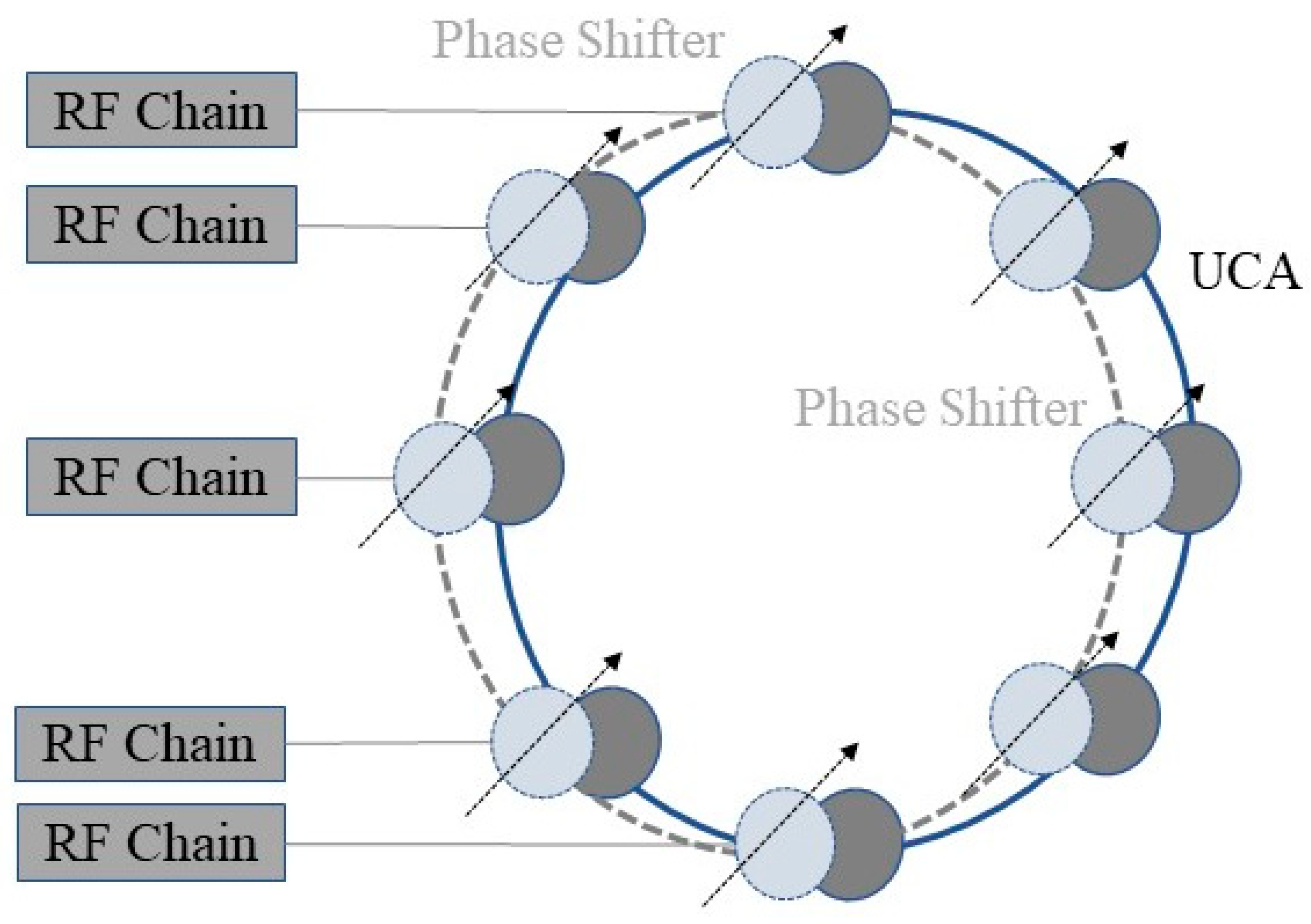
Figure 3.
Proposed multi-backup beam recovery scheme.
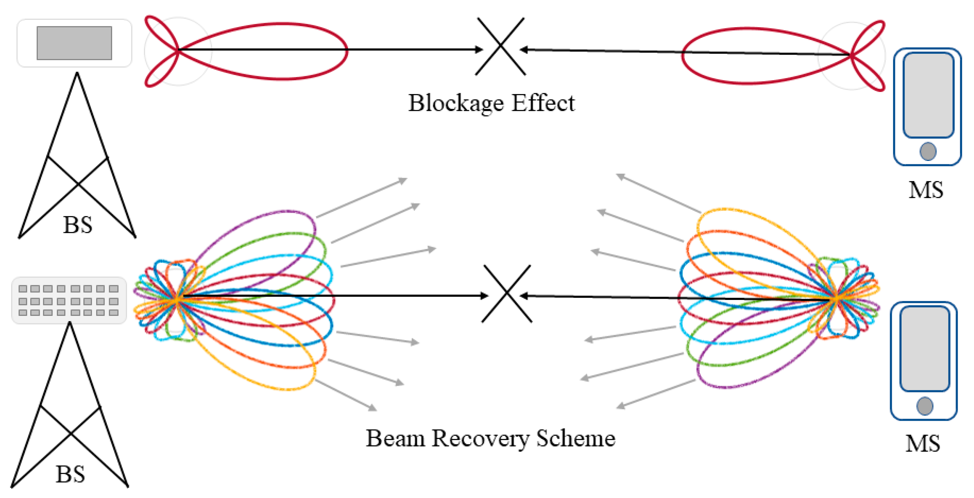
Figure 4.
Spectral efficiency for various blockage parameters.

Figure 5.
Power delay profile for conventional schemes (adjacent beam and aggregation).
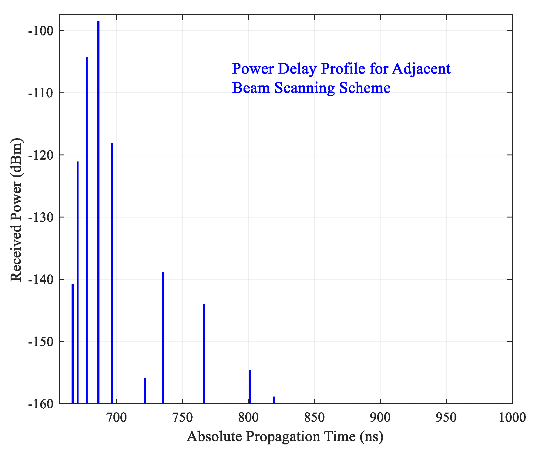
Figure 6.
Power delay profile for proposed multi-backup scheme.

Figure 7.
Recovery time for the proposed multi-backup scheme at various beam numbers.


Table 1.
System parameters.
| Category | Parameter | Value |
|---|---|---|
| System | (GHz), (MHz), (dBm) | 28, 700, 30 |
| Arrays | a,,,, | 1, 5, 256, 256 |
| Channel | (dB) , d (dB), | 1, 3, 5, 250, 0–1 |
| Path loss | (m), , | 5, 2.6, 4 |
| Spectral efficiency | Ω, | 2, 10 |
© 2019 by the author. Licensee MDPI, Basel, Switzerland. This article is an open access article distributed under the terms and conditions of the Creative Commons Attribution (CC BY) license (http://creativecommons.org/licenses/by/4.0/).
Share and Cite
MDPI and ACS Style
Aldalbahi, A. Multi-Backup Beams for Instantaneous Link Recovery in mmWave Communications. Electronics 2019, 8, 1145. https://doi.org/10.3390/electronics8101145
AMA Style
Aldalbahi A. Multi-Backup Beams for Instantaneous Link Recovery in mmWave Communications. Electronics. 2019; 8(10):1145. https://doi.org/10.3390/electronics8101145
Chicago/Turabian StyleAldalbahi, Adel. 2019. "Multi-Backup Beams for Instantaneous Link Recovery in mmWave Communications" Electronics 8, no. 10: 1145. https://doi.org/10.3390/electronics8101145
Note that from the first issue of 2016, this journal uses article numbers instead of page numbers. See further details here.