Article

A Semi-Floating Gate Memory Based on SOI Substrate by TCAD Simulation

School of Microelectronics, Fudan University, Shanghai 200433, China
*
Authors to whom correspondence should be addressed.
Electronics 2019, 8(10), 1198; https://doi.org/10.3390/electronics8101198
Submission received: 18 September 2019 / Revised: 9 October 2019 / Accepted: 16 October 2019 / Published: 21 October 2019
(This article belongs to the Section Semiconductor Devices)

Abstract

:
Over the past decade, the dimensional scaling of semiconductor electronic devices has been facing fundamental and physical challenges, and there is currently an urgent need to increase the ability of dynamic random-access memory (DRAM). A semi-floating gate (SFG) transistor has been proposed as a capacitor-less memory with faster speed and higher density as compared with the conventional one-transistor one-capacitor (1T1C) DRAM technology. The integration of SFG-based memory on the silicon-on-insulator (SOI) substrate has been demonstrated in this work by using the Sentaurus Technology Computer-Aided Design (TCAD) simulation. An enhancement in retention characteristics, anti-disturbance ability, and fast writing capability, have been illustrated. The device exhibits a low operation voltage, a large threshold voltage window of ~3 V, and an ultra-fast writing of 4 ns. In addition, the SOI-based memory has shown a much-improved anti-irradiation capability compared to the devices based on bulk silicon, which makes it much more attractive in broader applications.

1. Introduction

The continuous complementary metal-oxide-semiconductor (CMOS) scaling to achieve more powerful central processing unit (CPU) has reached limits imposed by the heat dissipation and power consumption. There have been extensive efforts to develop high-performance memory as the local CPU memory replacing the conventional one-transistor one-capacitor (1T1C) dynamic random-access memory (DRAM) [1]. In 1T1C-DRAM, the charges are stored in the capacitor, which requires refreshing every 64 ms. Various new-concept capacitor-less memory devices have been proposed to achieve faster speed and higher density [2,3]. A semi-floating gate (SFG) transistor can work at low voltages by taking advantage of the interband tunneling mechanism for the carrier transport similar to that in a tunnel field-effect transistor (TFET) [4,5,6]. Different from the 1T1C-DRAM, the charges are stored in the semi-floating gate in the SFG memory with an embedded TFET for carrier charging, enabling higher writing speed with low operation voltage and suppressed leakage current [7,8,9]. However, in an SFG transistor built on a bulk silicon substrate, the floating gate potential becomes too high after writing-1. Meanwhile, the semi-floating gate structure is not insulated from the bottom of the device. Thus, the unbalanced potential distribution results in the generation of leakage current from the floating gate to the substrate. Such leakage has a significant impact on the memory function of the device during the hold state, and the fluctuation in the amount of charge in the floating gate can cause data storage errors in severe cases. In this work, we simulate SFG transistor devices on silicon-on-insulator (SOI) substrates using Sentaurus Technology Computer-Aided Design (TCAD) tools. The SOI substrate can solve the above problems by suppressing short channel effects and reducing the parasitic capacitance [10,11]. There are other 1T-DRAM structures and recent concepts such as A2-RAM, UTBOX (Ultra-Thin Buried Oxide) devices, Z2-FET (Zero Impact Ionization and Zero Subthreshold Slope FET). In 2011, scientists proposed the A2RAM memory cell, which is a new concept of a capacitor-less DRAM cells for Fully Depleted SOI with the advantages of a single gate and low voltage operation [12]. A2RAM has a buried N-type layer of SOI transistor that can short circuits the source and drain (S/D) regions [13]. In addition, the Z2-FET is the comprehensive model for field-effect pnpn devices. The silicon film is highly doped at both ends to form n+ and p+ regions. Between the two ends is an undoped region. The two gates on the front and back are negatively biased, so there are lots of holes in the left side and lots of electrons on the right side. By applying a bias voltage between n+ and p+ contacts in the forward direction, the diode voltage, which increases with the gate voltage, suddenly changes from a low current state to a high current state [14]. The UTBOX devices are similar to the traditional SOI technology except for very thin buried oxide thicknesses (less than 50 nm). The thinner buried insulator has the advantages of good threshold voltage control, good thermal resistance, and good floating body effect. On the other hand, the buried oxide emphasizes the effect of the cell/substrate interface. To overcome this problem, a higher doped region, called the ground plane, is added to minimize the loss of this interface. This makes the substrate more controllable to the channel, and it does not interfere with the operation of the device due to loss of capacitance [11]. In this work, we have improved the structure by connecting the floating gate and the drain through a tunneling field-effect transistor (TFET). A tunneling field-effect transistor is used to control the charge and discharge of the floating gate, thereby forming a dynamic memory, and it is compatible with standard CMOS processes and does not require the integration of new materials. Semi-floating gate transistors (SFGTs) do not require significant changes to existing integrated circuit fabrication processes. Significantly improved writing speed (4.8 ns) and reduced leakage current have been observed. Moreover, the anti-irradiation capability of SOI-based SFG devices is also remarkably higher than that of bulk silicon-based devices. Such integration of SFG devices on the SOI substrate combines the intrinsic advantages afforded by the SOI structure with the novel SFG-based memory technology. This can pave an attractive pathway towards high-performance DRAM in processors with potential applications in optimizing the radiation response of advanced CMOS devices.

2. Device Structure and Basic Electrical Characteristics

A semi-floating gate (SFG) transistor consists of a TFET and a MOSFET with a semi-floating gate. The device modeling simulation of SOI-based SFG transistor is based on a 20-nm technology node. The device fabrication process is schematically shown in Figure 1. The SOI substrate is p+ doped with boron, and the channel of the TFET is n- doped with As. The embedded TFET is formed by the p-doped floating gate of the SFG and the n+ doped drain area through the opened window. Figure 2a shows the doping concentration distribution of SFG transistors based on a SOI substrate. Figure 2b measures the low-scanning-speed transfer curve loops of SFG transistor. Control gate voltage (VCG) is swept between −2 V and 2 V while drain voltage (VD) is maintained at 0.5 V. The operations of writing-1 and erasing change the threshold voltage (Vth) by changing the potential in the floating gate of the SFG transistor. The drain current in state-1 is about 4.1 μA/μm, and it is about 0.4 nA/μm in state-0. For the writing-1 operation, the positive bias at the drain and the negative VCG (for example, VD = 0.5 V, VCG = −2 V) inverses the extension area from n+ to p-type. The p-n junction formed by the drain of the SFG transistor and the floating gate is reversely biased. Therefore, the electron tunnels from the conduction band of the p+ area to the valence band of n+ area following the interband tunneling mechanism of tunnel field-effect transistor (TFET). The current flows from the drain to the semi-floating gate, and the SFG potential is increased. On the other hand, during the erasing operation, the TFET becomes a forwardly biased p-n junction, and the holes in the floating gate are drained. The SFG potential thus drops, and the Vth of the transistor increases. During the data read phase, the entire semi-floating gate transistor functions like the operation of a normal metal-oxide-semiconductor field-effect transistor (MOSFET), that is, both the control gate and the drain are positively biased, and the channel inversion generates electrons to form a drain current. Since the potentials in the second half of the floating gate are different after erasing and writing “1”, the threshold voltages of the transistors are different. As a result, under the same VCG, two significantly different drain currents could be obtained. Therefore, we can distinguish the data stored in the semi-floating gate by the drain current. The conditions of the data retention phase are that the control gate is not applied with voltage, the drain is positively applied, the p-n junction is kept reverse biased, and no charging and discharging of the semi-floating gate occurs.
Figure 2c shows the second cycle of normalized current curves of the SFG transistor, considering the fact that the second cycle is more stable than the first cycle in the electrical measurement. It can be observed that the reading current after the erase state is as low as 0.87 μA/μm due to the lower SFG potential. After writing-1, the SFG potential is relatively higher. The reading current can be as high as 9.9 μA/μm, and the current ratio between the state “1” and the erased state is ~11. The changes that occur in the SFG can be seen more intuitively in Figure 2d. As the applied voltage changes, the charge in the half floating gate is erased or written, and its potential changes accordingly. The change of the SFG potential in the second cycle can be extracted in TCAD, and the values after erasing and after writing-1 are −0.46 V and −0.16 V, respectively. Such a change in the SFG potential further causes the shift in Vth.

3. Simulation and Results

In order to optimize the operating conditions of the SFG transistor, we have tested simulations with different erase/write-1 VCG operation voltages and time to extract the change in the SFG potential. The parameters (voltage) we used in the simulation are given in Table 1. It should be noted that although prolonged operation time could enable better erasing or writing in the device (Figure 3a,b), the power consumption will also be increased. The moderate operation time of 4.8 ns has been used in the following simulations. Figure 3c,d show that the SFG potential varies with the different VCG during writing-1 and erasing operations. From the results shown in Figure 3, the SFG potential changes with different operation time, and VCG. In other words, the erasing and writing speed can be manually adjusted by manipulating the voltage and the time of reading and writing sequence.
Figure 4a,b show the two-dimensional (2D) distribution of the band-to-band generation rate and the band structure of the SFG transistor during write-1 operation, respectively. The VCG bias is negative, while VD is positive, which is given in Table 1. As stated before, the embedded TFET is composed of the p-i-n area of the SFG, and the drain is turned on. In the band-to-band tunneling (BTBT) model, the electrons tunnel at the interface, as shown in Figure 4b, and the BTBT generation rate is the highest at the interface.
The retention characteristics of the SFG-based memory is shown in Figure 4c. As discussed above, the SFG potential will be much higher after writing-1 operation leading to possible current flow from the floating gate to the drain, causing leakage. The leakage current will severely degrade the electrical performance, including the data retention capability. In addition to the usage of SOI structure to prevent the leakage from SFG to the substrate, increasing the drain potential can be expected to retain state-1 in the memory device. As shown in Figure 4c, with VD = 0.5 V and VCG = 0 V, the memory window is still large enough between the state-1 and the state-0 after 1-second retention. The states “0” and “1” are written into the semi-floating gate separately, and then both VCG and VD are fixed at the value of the hold process. The results, shown in Figure 4c, show that the state “0” and “1” can be held for 1 s, which is in line with the requirements of the DRAM application.
The anti-disturbance capability is also a key criterion for a memory device, which could be integrated into memory cell arrays towards multi-bit data storage. This is because the operating voltage has become much lower, which can easily lead to the blurring between various memory states or individual memory cells by even a slight disturbance. In our simulation, the memory cell array is paged-operated, so the voltage of the word line (VCG) is the same. When VD crosstalk is introduced in the state-0, VD of the TFET will be higher than the SFG potential, and holes will flow from the drain to the SFG. Therefore, SFG potential in state-0 will be close to that in state-1. As shown in Figure 4d, the SFG-memory is in a hold state before each disturbance. In Table 1, we used 0.5 V and 1 V of VD voltages. When the hold voltage of 0.5 V is changed to the crosstalk voltage of 1 V, the SFG potential in state-1 and state-0 can be distinguished from each other even with 10 ms of crosstalk.
One of the major advantages of using the SOI substrate is the enhancement of the anti-irradiation capability. We have further studied the radiation response of the SOI-based SFG transistor devices. Figure 5a,b show the heavy-ion charge density of the transistor after single-particle incident comparing the bulk silicon device and the SOI-based device, respectively. We extract the transient pulse current after a single-particle incident. As shown in Figure 5c, the SOI device has a much smaller pulse peak (1.5 μA) than the bulk silicon-based device (150 μA) under the same incident condition. This is because, with the same transistor structure and single-event incident simulation, more electron-hole pairs will be generated in the bulk silicon-based device compared to the device on SOI due to the lack of oxide layer blocking.

4. Conclusions

In this work, we have designed an SFG-memory based on the SOI substrate by using the Sentaurus TCAD simulation. As compared to the conventional bulk Si, the SOI structure can greatly improve the current leakage in the SFG transistors enabling better charge carrier transport efficiency and memory retention property. By engineering the operation voltage and operation time, the SFG-based memory has shown fast writing and erasing speed, good data retention, and anti-disturbance capabilities. SFG transistors can replace a portion of the static random-access memory (SRAM). The traditional SRAM requires six MOSFET transistors to form a memory cell with a large footprint. The SFG transistor can form a memory cell with a single transistor and has a storage speed close to that of a memory cell composed of six MOSFET transistors. Floating-gate transistors could also be used in the field of DRAM. The industry has been looking for a capacitor-less device technology that could be used to fabricate DRAMs. A DRAM composed of SFG transistors can realize the full functionality of conventional DRAM without capacitors. Not only is the cost significantly reduced, but the integration is higher, and the read and write speed is faster. In addition, the anti-irradiation ability of the SFG transistor is also enhanced by using the SOI substrate. Our results demonstrating the SFG device technology combining the advanced substrate structure is very promising in future on-chip memory applications as well as power device integrations.

Author Contributions

Writing—Original Draft—H.L.; Validation—H.L.; Methodology—C.W.; Writing—Review & Editing—L.C. and H.Z.; Supervision—Q.S.

Funding

This research was funded by the NSFC (61522404 and 61704030), 02 State Key Project (2017ZX02315005), Program of Shanghai Subject Chief Scientist (18XD1402800), and the Support Plans for the Youth Top-Notch Talents of China.

Conflicts of Interest

The authors declare no conflict of interest.

References

  1. Jiang, S.Y.; Yuan, Y.; Wang, X.; Chen, L.; Zhu, H.; Sun, Q.Q.; Zhang, D.W. A Semi-Floating Gate Transistor with Enhanced Embedded Tunneling Field-Effect Transistor. IEEE Electron Device Lett. 2018, 39, 1497–1499. [Google Scholar]
  2. Heinrich, A.; Loth, S. A logical use for atoms. Science 2011, 332, 1039–1040. [Google Scholar] [CrossRef] [PubMed]
  3. THamamoto, T.; Ohsawa, T. Overview and future challenges of floating body RAM (FBRAM) technology for 32 nm technology node and beyond. Solid-State Electron. 2009, 53, 676–683. [Google Scholar] [CrossRef]
  4. Wang, P.F.; Lin, X.; Liu, L.; Sun, Q.Q.; Zhou, P.; Liu, X.Y.; Liu, W.; Gong, Y.; Zhang, D.W. A semi-floating gate transistor for low- voltage ultrafast memory and sensing operation. Science 2013, 341, 640–643. [Google Scholar] [CrossRef] [PubMed]
  5. Nirschl, T.; Wang, P.F.; Weber, C.; Sedlmeir, J.; Heinrich, R.; Kakoschke, R.; Schrufer, K.; Holz, J.; Pacha, C.; Schulz, T.; et al. The tunneling field effect transistor (TFET) as an add-on for ultra-low-voltage analog and digital processes. In Proceedings of the IEDM Technical Digest, IEEE International Electron Devices Meeting, San Francisco, CA, USA, 13–15 December 2004; pp. 195–198. [Google Scholar]
  6. Koga, J.; Toriumi, A. Three-terminal silicon surface junction tunneling device for room temperature operation. IEEE Electron Device Lett. 1999, 20, 529–531. [Google Scholar] [CrossRef]
  7. Aydin, C.; Zaslavsky, A.; Luryi, S.; Cristoloveanu, S.; Mariolle, D.; Fraboulet, D.; Deleonibus, S. Lateral interband tunneling transistor in silicon-on-insulator. Appl. Phys. Lett. 2004, 84, 1780–1782. [Google Scholar] [CrossRef] [Green Version]
  8. Hansch, W.; Fink, C.; Schulze, J.; Eisele, I. A vertical MOS-gated Esaki tunneling transistor in silicon. Thin Solid Film 2000, 369, 387–389. [Google Scholar] [CrossRef]
  9. Anghel, C.; Hraziia, A.; Gupta, A.; Amara, A.; Vladimirescu, A. 30-nm Tunnel FET With Improved Performance and Reduced Ambipolar Current. IEEE Trans. Electron Devices 2011, 58, 1649–1654. [Google Scholar] [CrossRef]
  10. Hisamoto, D.; Kimura, S.; Kaga, T.; Nakagome, Y.; Isoda, M.; Nishida, T.; Takeda, E. A New Stacked Cell Structure for Giga-Bit DRAMs using Vertical Ultra-Thin SO1 (DELTA) MOSFETs. In Proceedings of the IEDM Tech. Dig., Washington, DC, USA, 8–11 December 1991; pp. 959–961. [Google Scholar]
  11. Ohtou, T.; Saraya, T.; Hiramoto, T. Variable-Body-Factor SOI MOSFET With Ultrathin Buried Oxide for Adaptive Threshold Voltage and Leakage Control. IEEE Trans. Electron Devices 2008, 55, 40–47. [Google Scholar] [CrossRef]
  12. Rodriguez, N.; Cristoloveanu, S.; Gamiz, F. Novel Capacitorless 1T-DRAM Cell for 22-nm node Compatible with Bulk and SOI substrates. IEEE Trans. Electron Devices 2011, 58, 2371–2377. [Google Scholar] [CrossRef]
  13. Okhonin, S.; Nagoga, M.; Sallese, J.; Fazan, P. A Capacitorless 1T-DRAM Cell. IEEE Electron Device Lett. 2002, 23, 85–87. [Google Scholar] [CrossRef]
  14. Wan, J.; Le Royer, C.; Zaslavsky, A.; Cristoloveanu, S. Progress in Z2-FET 1T-DRAM: Retention time, writing modes, selective array operation, and dual bit storage. Solid State Electron. 2013, 84, 147–154. [Google Scholar] [CrossRef]
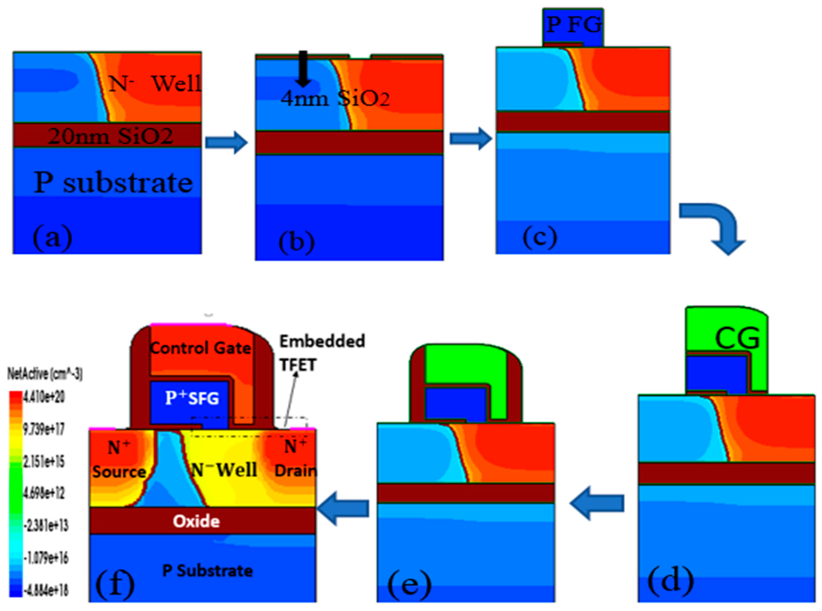
Figure 1. Schematic illustration of the device fabrication process. (a) SOI substrate and N- well formation. (b) 4 nm SiO2 deposition. (c) P-type floating gate formation. (d) Control gate and (e) spacer formation. (f) N+ doped S/D formation and doping concentration distribution of the SFG transistor based on the SOI substrate.
Electronics 08 01198 g001
Figure 2. (a) Doping the concentration distribution of the SFG transistor based on an SOI substrate. (b) Low-speed hysteresis transfer curve of the device. (c) The normalized reading and writing operation currents of the device. (d) Changes in the SFG potential during one cycle.
Electronics 08 01198 g002
Figure 3. (a) The SFG potential varies with the time of writing-1. (b) The SFG potential decreases as the erasing time increases. (c) The SFG potential varies with VCG during writing-1 with 4.8 ns operation time. (d) The SFG potential of state 0 decreases as VCG increases during the erasing operation.
Electronics 08 01198 g003
Figure 4. (a) The BTBT rate profile of the SFG transistor. (b) Band diagram when writing “1”. (c) The SFG potential in state-1 and state-0 during the standby time for 1 s. (d) The SFG potential in state-0 and state-1 which varies with different disturbance times.
Electronics 08 01198 g004
Figure 5. (a) Heavy-ion charge density of bulk silicon devices after a single-particle incidence. (b) Heavy ion charge density of SOI device after single particle incidence. (c) Transient pulse current after single-particle incident.
Electronics 08 01198 g005
Table 1. Time and operation voltage of the SFG transistor on the SOI.
EraseWrite-1ReadStandby
VCG (V)1.3−20.50
VD (V)0.51.01.00.5
VS (V)0000
VSub (V)−0.5−0.5−0.5−0.5
Time (ns)4.84.84.87.8