Article

Aging-Resilient Topology Synthesis of Heterogeneous Manycore Network-On-Chip Using Genetic Algorithm with Flexible Number of Routers

1
Department of Electrical and Computer Engineering, College of Information and Communication Engineering, Sungkyunkwan University, Suwon, Gyeonggi-do 16410, Korea
2
Department of Artificial Intelligence, Sungkyunkwan University, Suwon, Gyeonggi-do 16410, Korea
*
Author to whom correspondence should be addressed.
Electronics 2019, 8(12), 1458; https://doi.org/10.3390/electronics8121458
Submission received: 5 November 2019 / Revised: 22 November 2019 / Accepted: 25 November 2019 / Published: 2 December 2019
(This article belongs to the Section Computer Science & Engineering)

Abstract

:
As semiconductor processes enter the nanoscale, system-on-chip (SoC) interconnects suffer from link aging owing to negative bias temperature instability (NBTI), hot carrier injection (HCI), and electromigration. In network-on-chip (NoC) for heterogeneous manycore systems, there is a difference in the aging speed of links depending on the location and utilization of resources. In this paper, we propose a heterogeneous manycore NoC topology synthesis that predicts the aging effect of each link and deploys routers and error correction code (ECC) logic. Aging-aware ECC logic is added to each link to achieve the same link lifetime with less area and latency than the Bose-Chaudhuri-Hocquenghem (BCH) logic. Moreover, based on the modified genetic algorithm, we search for a solution that minimizes the average latency while ensuring the link lifetime by changing the number of routers, location, and network connectivity. Simulation results demonstrate that the aging-aware topology synthesis reduces the average latency of the network by up to 26.68% compared with the aging analysis and the addition of ECC logic on the link after the topology synthesis. Furthermore, topology synthesis with aging-aware ECC logic reduces the maximum average latency by up to 39.49% compared with added BCH logic.

1. Introduction

In the recent decades, the parallel communication performance of network-on-chip (NoC) has been demonstrated in manycore system-on-chip (SoC) interconnect architectures [1,2,3,4]. Recently, research has been actively conducted on heterogeneous manycore architectures that integrate processing elements (PEs) on a single chip to form a chip multiprocessor (CMP) solution [2,4]. For the multi-level integration of the heterogeneous manycore system, existing NoC architectures such as the ring, mesh, and tree exhibit limitations in terms of providing scalability and low latency. The NoC for such a system should have dedicated connectivity customized by the interconnect designer.
In NoCs for heterogeneous manycore architectures, not only the communication load between PEs, but also their size and location must be considered. Even if communication loads between two PEs are high, they can be placed further away to mitigate power and heat issues. In this case, the PEs may need to communicate across multiple routers. When defining the connectivity of NoC, determining the location of routers and links by considering these physical elements together is referred to as NoC topology synthesis [5,6,7]. Various heuristic-based topology synthesis techniques were studied to improve NoC performance in heterogeneous manycore NoC designs. Existing schemes have applied a fixed number of routers in the chip. These methods make it possible to find a reasonable solution in NoC with a specific number of routers. However, in situations where the number of routers is not assigned, algorithms must be executed several times for different numbers of routers, which requires additional computation time.
In contrast, due to the miniaturization of semiconductor processes, delay faults in communication data due to the aging of flip-flops and metal wires have become a significant concern in the SoC interconnect design [8,9,10]. In the nanoscale process, aging-induced delay faults occur mainly due to negative bias temperature instability (NBTI), hot carrier injection (HCI), and electromigration [11,12,13,14,15]. NBTI and HCI increase the threshold voltage of the transistors, and electromigration increases the resistance in metal wires, resulting in longer data transfer delay [8,9,15].
Few studies have considered the aging effect in the high-level design of the on-chip interconnect, because it was treated as a low-level design problem. However, recent studies show that in the topology synthesis of heterogeneous manycore NoC, the aging process can be predicted based on the length and communication load of each link [14,15,16]. If the aging effect of each link is taken into consideration during the NoC topology synthesis, it is possible to reduce the performance degradation through the placement of interconnect modules and links. Moreover, this will aid in the recovery of aging resilience by correcting the error even if a delay fault occurs by using the error correction logic.
The forward error correction, based on error correction code (ECC) logic such as Hamming and Bose-Chaudhuri-Hocquenghem (BCH), is widely used to improve communication reliability in NoC [17,18,19]. This logic is efficient in correcting random errors, because they have uniform error correction capability for each bit. However, links with non-uniform error rates per bit require ECC logic with high correctability, latency, area, and power consumption, considering the worst case. NoC links have non-uniform reliability even in bits, due to different initial crosstalk noise and aging-induced delay [11,12,13]. In these links, the design of customized ECC logic is needed to improve aging resilience and latency.
In this regard, we propose a topology synthesis that optimize the average latency of the network while guaranteeing the lifetime of the links by considering the aging process of NoC links. There are three main contributions to this research. First, the topology synthesis considering the aging effects of the links is performed to prove that low-level design factors can be reflected in the NoC design. Second, non-linear ECC logic is generated based on the possibility of aging-induced delay fault on links, achieving the same level of reliability with less overhead than BCH logic. Third, a topology synthesis employing an improved genetic algorithm (GA) is proposed, which flexibly allocates the number of routers to be placed on a chip to determine the reasonable number.
The rest of this paper is organized as follows. In Section 2, the related studies of this research field are introduced in terms of aging-resilient design, error recovery scheme, and topology synthesis. In Section 3, the problem definition and flow of aging-resilient topology synthesis are presented. In Section 4, the aging-induced delay model of each link and the aging-aware ECC logic generation method are proposed. In Section 5, a modified GA-based topology synthesis technique is described, which flexibly assigns the number of routers. Simulation results shown in Section 6 verify the contributions presented above. Conclusions are given in Section 7.

2. Related Works

2.1. Aging-Resilient Design for NoC

The lifetime problem of NoC links due to the aging process was solved by selecting an appropriate routing strategy [15,16,17,18,19]. Boraten et al. proposed an adaptive routing method that guarantees regular communication by assigning a bypass path in the event of a link failure. They achieved high reliability owing to the path diversity, especially in networks with high bisection bandwidth. In contrast, Rohbani et al. focused on the communication load on the links and their effect on the aging speed. They conducted a study to balance the load on all links through oblivious routing, which assigns different paths for communications thereby avoiding high loading of links.
We solve this problem at the front-end compared with the previous works, which optimizes not only link lifetime, but also the average latency. Based on the analysis of the aging process for each link, a topology synthesis solution is generated that optimizes the lifetime and average latency of the NoC. Numerous studies have analyzed the NoC aging process [20,21,22,23,24,25]. This includes studying the threshold voltage shift model by NBTI and HCI and the wire resistance shift model by electromigration, which are the leading causes of NoC aging. This study confirms the aging process of each link based on previous research and proposes a suitable network component arrangement.

2.2. Error Recovery Scheme in NoC Datapath

Data error growth is a critical problem even in NoC, where links are shorter links than those in buses. Therefore, various ECC-based solutions have been developed for the error correction. End-to-end error correction scheme using error recovery techniques in the transmission layer were introduced [19,26]. In contrast, switch-to-switch error correction has been proposed to apply error recovery techniques in network layers to optimize the link unit reliability of NoC [26,27,28]. End-to-end studies add ECC logic to the PE’s inputs and outputs, hence requiring less logic than the switch-to-switch error correction, which involves ECC logic on each link. Nevertheless, this technique requires ECC with high correctability considering error overlap, and it causes NoC malfunction in the event of an error in the head flit.
The proposed method should guarantee proper reliability for each link based on the aging-induced delay fault analysis of each link. Therefore, we employ the switch-to-switch error correction. Because the switch-to-switch method requires more logic than the end-to-end technique, the ECC logic must achieve maximum communication reliability with minimum correctability. In some studies, it was confirmed that there is a variation in the link lifetime due to the difference in initial and aging-induced delay of each wire [11,12,13]. In the aging analysis, we identify the possibility of aging-induced delay faults and generate low-cost ECC logic with specialized correction capabilities.

2.3. Topology Synthesis of NoC

Topology synthesis, which defines the location and connectivity of NoC components, has been studied to optimize parameters such as average latency and power consumption [5,29,30,31]. These studies assumed a heuristic approach to solve the NP-hard problem of NoC design. Leary et al. performed GA-based optimization, which does not quickly converge to sub-optimal solutions [30]. Soumya et al. proposed an optimization technique based on particle swarm optimization [5]. This study expands the number of cases that can be generated by a more flexible positioning of routers on the chip.
The proposed technique proceeds with GA-based topology synthesis; however, it improves each step in the algorithm to meet the contribution of arranging various numbers of routers and assigning an aging resilience to each link. The number of routers employed is changed when topology synthesis cases are created and modified to consider individuals with varying numbers of routers. Moreover, to fabricate a case that guarantees aging resilience, when evaluating average latency, the latency of the ECC logic generated in each link needs to be considered, and a local search process needs to be provided to improve it.

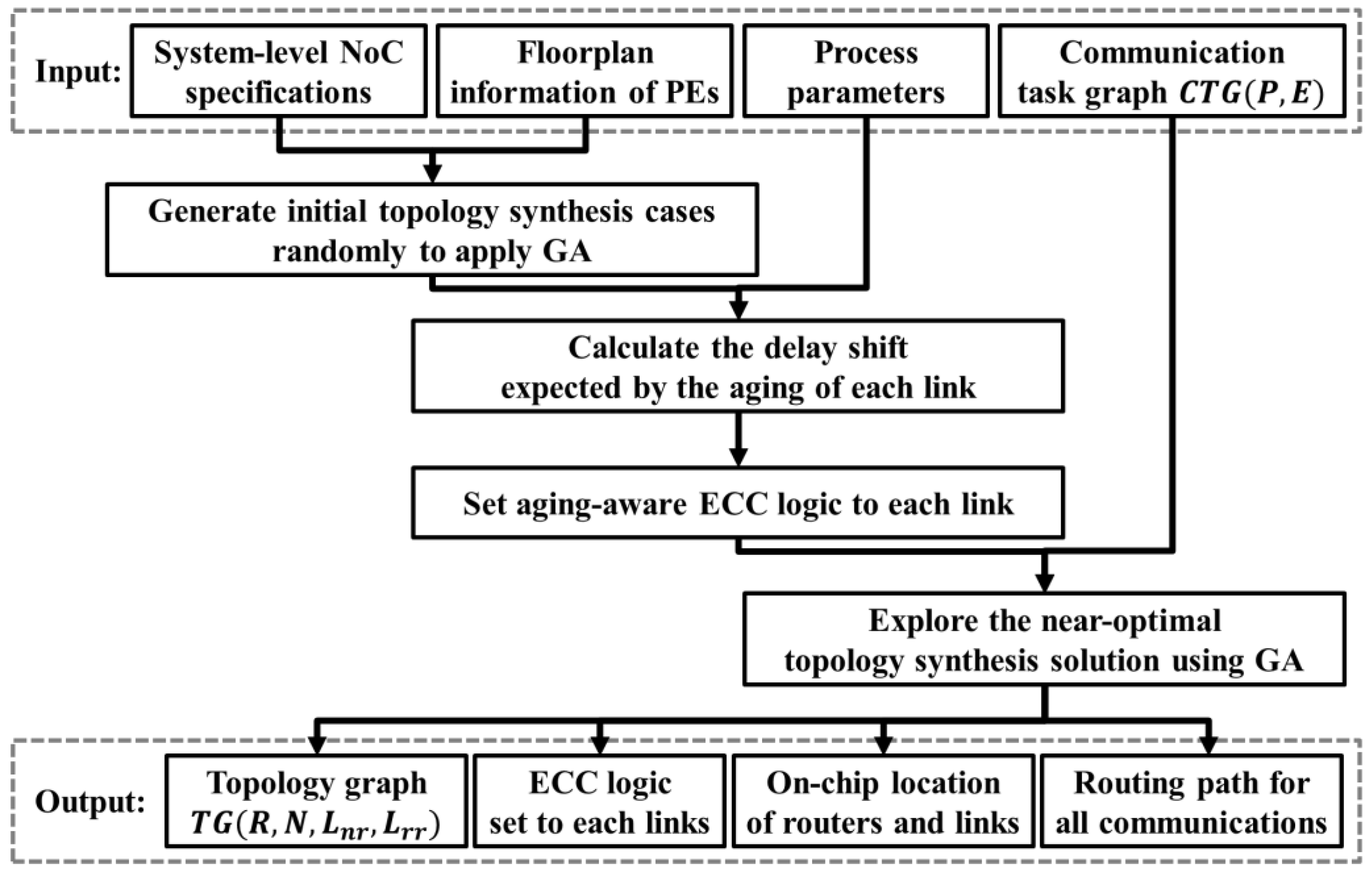
3. Overall Flow of Proposed Topology Synthesis

The topology synthesis proposed in this study proceeds with the flow, as shown in Figure 1. First, four types of inputs are defined: The system-level NoC specification, virtual floorplan information of the PEs in the chip, process parameters of the chip, and the communication task graph. The system-level NoC specification includes the parameters that must be followed in the NoC design, such as maximum link length constraints, bandwidth, maximum number of ports in the router, number of virtual channels, and maximum number of routers available. The virtual floorplan of the PE provides information on which PEs are arranged in the chip. The process parameters include the resistance per unit length of the wire, permittivity, propagation delay of the flip-flops, and the setup time. This information is used for analyzing the delay extended by the initial state and aging of each link on NoC. The communication task graph C T G ( P ,   E ) is a weighted directed graph, where each vertex p i P corresponds to a PE in the graph, and each directed edge e i , j E represents communication from PE p i to PE p j . The edge is labeled with a value w i , j equal to the bandwidth requirement of the communication from p i to p j .
Four types of outputs are available as a result of the NoC topology synthesis: The NoC topology graph, ECC logic added to each link, average latency expected by the system, and chip lifetime. The NoC topology graph is a directed graph T G ( R ,   N ,   L n r ,   L r r ) , where R is the set of routers used in the topology, N is the set of nodes, L n r represents the set of links between nodes and routers, and L r r represents the set of links between routers. L = L n r L r r depicts the set of all links. The ECC logic added to each link includes the error correction capability and hardware structure of the ECC logic to prevent aging-induced delay faults over the guaranteed lifetime. The on-chip location of routers and links contains the location of routers R and wiring information of links L n r and L r r in the NoC. The routing path for each communication depicts R ,   L n r , and L r r through which packets pass through all edges of C T G ( P ,   E ) .
The proposed design scheme should derive a topology synthesis solution that minimizes the average latency, while satisfying the constraints, using the input given above. First, we construct initial topology synthesis cases to apply a GA using NoC specifications and floorplan information. In the GA, each case is generated with randomness, because it is desirable to have the broadest possible search area. The prediction of the delay shift due to the aging process, based on process parameters and the communication load, is progressed in each link conductor of the generated initial cases. Subsequently, the possibility of failure during the aging period of each link is determined, and the generation of ECC logic suitable for the link progresses. Finally, the iterative GA drive searches the topology synthesis case, where the average delay is optimized.
Aging-resilient NoC topology synthesis generates the parameters and variables listed in Table 1 to express the problem. The aim of the proposed topology synthesis is to find the topology graph T G ( R ,   N ,   L n r ,   L r r ) , location of the router, and location of the link that can minimize the average delay. The objective function expressing the average delay can be generated as follows. If there is a physical link between routers r k and r l , and this link is included in the routing path of data transmission from PEs p i to p j , then the value of p a t h p i ,   p j r k ,   r l is 1. In this case, the latency in the transmission from r l to r k is the sum of the latency T r o u t e r consumed in the pipeline stage of the router and the latency of the ECC logic added to the link t p o r t r k n r l . Moreover, the total latency required for the packet transmission from p i to p j can be obtained by adding one clock cycle that applies data to the network layer from p i . Therefore, the problem of minimizing the average delay is equivalent to minimizing the following equation.
M i n i m i z e [ e i ,   j E w i ,   j ( 1 + r k ,   r l R , n < P O R T M A X ( T r o u t e r + t p o r t r k n r l ) p a t h p i ,   p j r k ,   r l ) ] .
The following is the set of constraints that the topology synthesis solution must satisfy.
  • The location of all routers cannot exist in the area where PEs are placed (i.e., router position constraint).
    p i P ,   r j R , ( p o s i r j x < p o s i p i x ) o r   ( p o s i r j y < p o s i p i y ) o r   ( p o s i p i x + s i z e p i x < p o s i r j x )   o r   ( p o s i p i y + s i z e p i y < p o s i r j y ) .
  • The physical path of all links cannot exist in the area where PEs are placed (i.e., link position constraint).
    p i P ,   r j R , ( w i r e p o r t r i n < p o s i p i x ) o r   ( p o s i r j y < p o s i p i y ) o r   ( p o s i p i x + s i z e p i x < p o s i r j x )   o r   ( p o s i p i y + s i z e p i y < p o s i r j y )   ( 0 < n < P O R T M A X ) .
  • Each PE must be connected to only one router (i.e., PE connection constraint).
    p i P ,   r i R l i n k p i , r j = 1 .
  • Routers must be connected such that a communication path with each other exists (i.e., link connection constraint).
    r i , r j R , p a t h r i , r j = 1 .
  • The length of the link between the PEs, routers, and between routers must be less than L M A X (i.e., maximum link length constraint).
    p i P ,   r j R ,   l e n p i , r j < L M A X .
    r i , r j R , l e n r i , r j < L M A X .
  • The number of ports in each router must not exceed P O R T M A X (i.e., maximum router port constraint).
    r j R ,   n u m _ p o r t r i < P O R T M A X .

4. Aging-Resilient Design of NoC with Non-Uniform ECC Assignment

4.1. Time Constraint of NoC Links

For the generation of aging-aware ECC logic, it is necessary to assess whether there is a delay fault for each link during its lifetime. Figure 2 provides the factors that affect the delay error of the data in the data transmission of inter-router links. R w i r e and C c o u p l i n g are the resistance and coupling capacitance of the link wire, respectively, and T is the period of the clock connected to the flip-flops. t w i r e p g , t f f p g , t f f s u are the propagation delay of the wire, propagation delay of the upstream flip-flop, and the setup time of the downstream flip-flop, respectively. The value of R w i r e and C c o u p l i n g can alter t w i r e p g . As the threshold voltage of the transistor inside the flip-flop increases, t f f p g and t f f s u also increase. In this case, the setup time constraint, as shown in Equation (9), must be satisfied to prevent the delay fault in the link.
t w i r e p g + t f f p g + t f f s u < T .
Immediately after the chip is manufactured, the interconnects in the chip that passed the defect test satisfy Equation (9). However, as time elapses, the value on the left side of Equation (9) increases due to the aging process. NBTI and HCI shift the threshold voltage of the transistor to increase t f f p g and t f f s u , and electromigration shifts the resistance of the link wire to increase t w i r e p g . If the left side of the relation becomes greater than T , an aging-induced delay fault occurs on the link.
We derive the aging speed of links based on the models specified in [23,24,25,26] and analyze the timing slack of links in their lifetime. In Section 4.2, NBTI, HCI, and the electromigration process, as well as the corresponding shift model are introduced. Section 4.2 describes a technique for generating ECC logic that provides differential reliability on a bit-by-bit basis, depending on whether a delay fault is predicted in each wire.

4.2. Aging-Induced Delay Model

This section assesses whether aging-induced delay faults occur on links. First, the threshold voltage shift model based on NBTI and HCI and the resistance shift model based on electromigration are introduced. Table 2 shows the contents and values of the parameters used to predict the aging process, including NBTI, HCI, and electromigration of the NoC link in the 32 nm process [15].
NBTI reveals one of the most critical aging effects on NoC routers [9]. The electric field on the gate insulator and the high-temperature state accelerate aging due to NBTI. This electric field separates the Si–H boundary generated in the process, creating a trap at the interface of the silicon and the gate insulator, and increasing the threshold voltage of the p-type transistor [4,5,11]. This study employs the NBTI model proposed in [23] presented in Equation (10). The model calculates the effect of operating voltage, temperature, stress period, and aging period on the transistor threshold voltage.
Δ V t h N B T I = ( n 2 K v 2 α C t 1 t ξ 2 t o x 2 ( 1 α ) ) n .
While NBTI has a destructive effect on p-type transistors, HCI is generally regarded as the most crucial reliability challenge of n-type transistors [7]. HCI occurs when the charge carrier is accelerated from the source to the drain of the transistor and exceeds the potential barrier between the gate insulator and the silicon, thereupon escaping the channel to increase the threshold voltage. The HCI effect on the threshold voltage is represented by the relationship in Equation (11) [24,25]. The parameters are described in Table 2.
Δ V t h H C I = q t o x t n ϵ o x × K 1 2 n C o x ( V g s V t h ) ( e E o x E 0 ) 2 1 2 n .
The electron flow inside interconnects with small cross-sectional areas moves the thermally-activated metal ions in the direction of the current flow. This effect accumulates metal ions at one end of the wire and makes the other end thinner. After some time, the electrical characteristics of the conductor change, and the RC delay of the conductor increases as the shape of the conductor changes [12]. Nowadays, the signal path of modern chips is made of copper with a higher conductance than aluminum. However, electromigration has become a bigger problem than in the past, because it has a more significant impact on copper than on aluminum [9]. Equation (12) represents the change in resistance R w of the wire, according to electromigration [26].
Δ R w = 2 R w γ A 0 D 0 t e Q a 2 R T a 1 2 γ A 0 D 0 t e Q a 2 R T a .
The π model can include the shift models presented above to analyze the left-hand side of Equation (9) using simulation program with integrated circuit emphasis (SPICE). This method allows high-precision analysis using the information in the technology library; however, it is difficult in terms of computation time as it requires the execution of many links. In this regard, Synopsys HSPICE simulation to determine the value of t w i r e p g + t f f p g + t f f s u is performed in advance on various V t h and R w . In this process, a 1.05 V supply voltage, 0.5 GHz clock frequency, and Synopsys 32 nm library is applied. The result is shown in Equation (13) and has a graph form like Figure 3. If t w i r e p g + t f f p g + t f f s u of the link with the aging effect is greater than 2 ns, an aging-induced delay fault is expected to occur on the link.
Δ t w i r e p g   + t f f p g + t f f s u = 411.2 V t h 3 + 0.001 R w 3 1.546 V t h 2 R w + 0.0257 V t h R w 2 146.7 V t h 2 0.014 R w 2 + 0.2037 V t h R w + 17.22 V t h + 0.1203 R w + 0.7621 .

4.3. Non-Uniform ECC Generation

After aging-induced delay fault analysis of link wires, ECC logic generation is performed to enhance reliability. This generates aging-aware error correction logic for bit-level error recovery based on the presence of a link delay fault, which is based on the aging effect predicted in each wire. First, to generate the fault syndrome of the aging-aware ECC, the wires of the link are classified into three groups based on the probability of a delay fault: The faulty wire group, semi-faulty wire group, and unfaulty wire group. Wires that are expected to have a delay fault in their lifetime and hence must be corrected are placed into a faulty wire group, and their number is expressed as N F G . Some wires are analyzed to prevent delay faults during their lifetime; however, with a small timing slack, delay faults in the wires may occur during practical use. Therefore, the clock period T is multiplied by a constant t m between 0 and 1 determined by the designer to specify a stricter timing margin. Wires with delays that do not exceed T , whereas they exceed t m T , are placed in semi-faulty wire groups, and their number is expressed as N S G . Finally, wires with latency lower than t m T are placed into an unfaulty wire group.
Syndromes should be generated based on the error correction capability to be given to each wire group. Because the wires in the faulty wire group are expected to cause a delay fault due to aging, they should always be correctable, and the number of syndromes required is 2 N F G . Because the wires of a semi-faulty wire group have low probability of occurrence of a delay fault, they do not need to be provided with a high-error correction capability. Therefore, a code is generated such that even if a delay fault occurs in one wire belonging to a semi-faulty wire group, the wire can be recovered. Thus, the number of error syndromes required for the semi-faulty wire group is N S G . The error correction will not be performed on a non-faulty wire group, because they are expected to have no delay fault.
Because the aging-aware ECC must consider not only the error-free situation, but also the fault situation for the faulty and semi-faulty wire groups. The total number of error syndromes of ( N S G + 1 ) × 2 N F G is required. For the ECC parity bits to represent all error syndromes, the minimum value of the number of parity bits p that satisfies condition (14) must be determined.
p < N F G l o g 2 ( N S G + 1 ) .
However, if a wire is added to the link to transmit the parity bit, the coupling capacitance of each wire changes and the delay increases, such that the number of wires in the faulty and semi-faulty wire groups may increase. Therefore, the delay estimation and the parity bit calculation must be repeatedly performed when the parity bit is added. This process is complete when the result of the re-executed parity bit calculation is same as the previous result.
For example, consider a data link with 8-bit data transmitted from w 1 to w 7 , as shown in Figure 4. If w 3 is a faulty wire, and w 2 and w 4 are semi-faulty wires, the N F G value of the link is 1, N S G is 2, and the minimum value of p that satisfies condition (5) is 3. If the number of faulty and semi-faulty wires is changed in a 12-bit wire with 4 bits of parity, whether the current p satisfies condition (5) must be verified. If w 4 is a faulty wire, and w 5 and w 6 are semi-faulty wires, then N F G is 2, N S G is 3, and the minimum value of p is 5. When the delay prediction is repeated on the 13-bit wire, and the minimum value of p is fixed to 5, the parity bit calculation required for the aging-aware ECC of the link is complete.
Subsequently, the generator matrix of the ECC logic for the error syndrome should be defined. Because the generator matrix must have different error syndromes for all error patterns that need to be corrected, the following conditions must be satisfied.
  • Condition (1). Each column of the matrix must be unique.
  • Condition (2). The result of the bitwise XOR operation between columns belonging to the faulty wire group should be unique.
  • Condition (3). The result of bitwise XOR operation between all the columns generated in Condition (2) and the columns belonging to the semi-faulty wire group must be unique.
All generator matrices can be determined with the above-mentioned conditions. This problem results in a Boolean satisfiability problem (SAT), and a solution can be found using a program such as the SAT solver.
Table 3 summarizes the generation matrix of the aging-aware ECC added to the link specified in Figure 4. Columns corresponding to bits 3 to 9 satisfy all conditions. By placing parity bits elsewhere than in an unfaulty wire group, the number of ones in the matrix is reduced.
The proposed aging-aware ECC logic has a significantly smaller number of syndromes compared with BCH logic, which corrects the same amount of errors. Thus, aging-aware ECC logic can achieve the same level of reliability with lower latency.

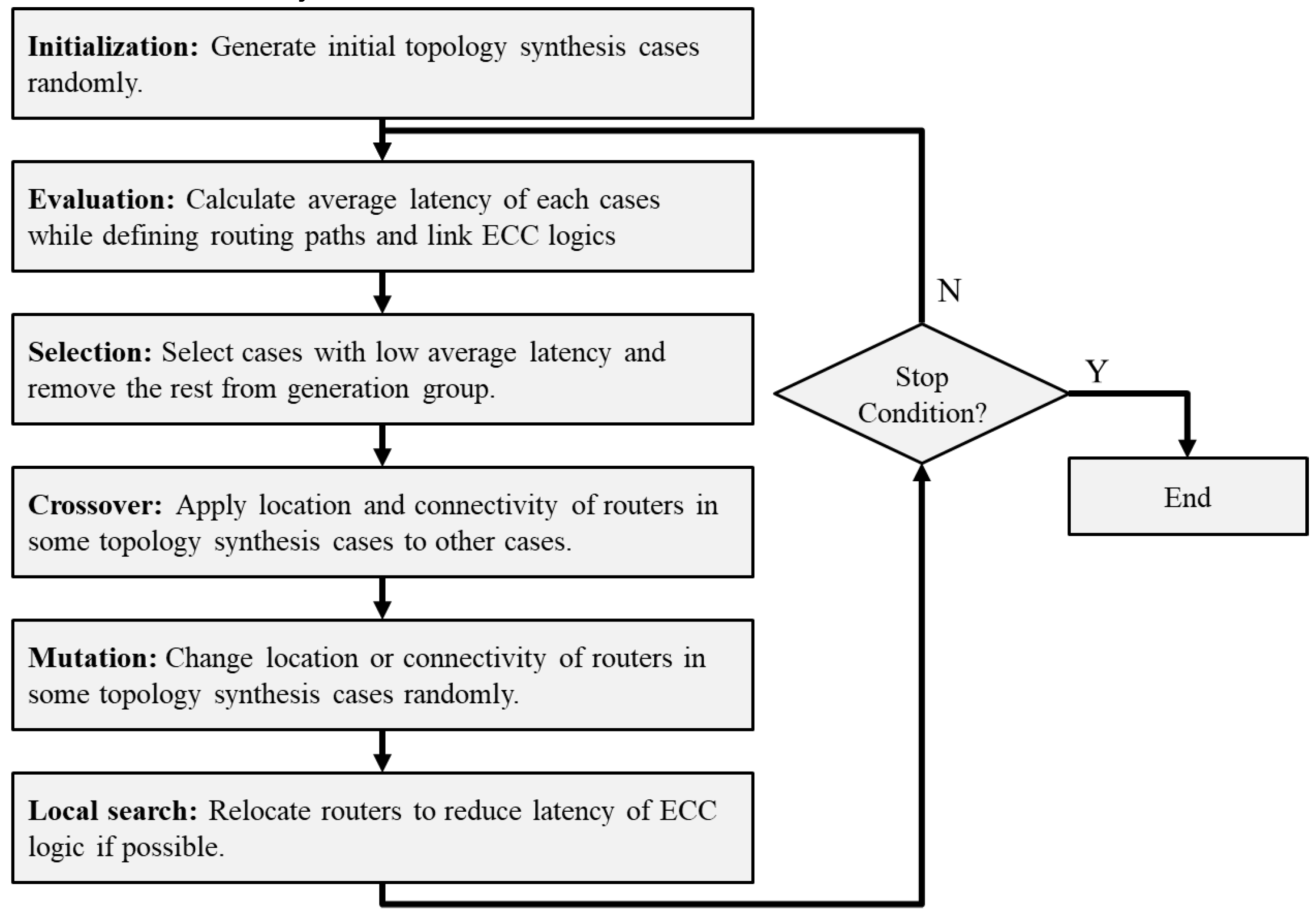
5. Average Latency Optimization Using Genetic Algorithm

Once it becomes possible to generate aging-aware ECC logics and analyze their latency, the average latency of topology synthesis cases can be optimized. Optimizing average latency by defining proper connectivity and location of routers and links is an NP-hard problem. Therefore, it is extremely time-consuming to search for a reasonable solution considering all possible cases. To address this, we propose a GA-based solution search. The GA is a heuristic algorithm that searches for reasonable solutions by recombining the internal characteristics of high-performance cases. The GA prevents the rapid convergence of non-optimal solutions through genetic crossover and mutation operations. Furthermore, GA has demonstrated outstanding performance in the field of NoC connectivity and routing path definitions, where partial performance improvements affect the performance of the overall system [29,30,31,32,33,34].
GA-based NoC topology synthesis proceeds according to the flowchart of Figure 5. First, an initial population of topology synthesis cases is generated to drive the algorithm. These cases are randomly generated such that they are evenly spaced across the search area. Second, the average latency evaluation for performance assessment is done on the generated cases. Here, aging-aware ECC logic is generated as described in Section 4, and the shortest routing paths are assigned. Third, the cases with lower average latency are selected as candidates for the next generation. Not only do they participate as components of the next generation, they are also used in genetic operations such as crossover, mutation, and local search. Fourth, for some of the selected cases, a crossover operation is performed to transmit the location and connectivity information of the internal router to the other cases. This process allows the combination of excellent characteristics of each case to improve the performance of the entire network. Fifth, mutation operations are performed in which the router location and connectivity of some cases are arbitrarily modified. This jump in the search area creates models with different characteristics from existing cases and prevents rapid convergence to the local optimum solution.
Sixth, unlike the conventional GA, local search is performed to improve the average latency of the network by adjusting the location and connectivity of routers in each case. When a router is relocated in a network maintaining the same connectivity, the wire delay of the links associated with that router changes. This change can reduce the number of syndromes required for ECCs added to each link and shorten the latency of logic. In addition, latency improvements can occur when the connectivity of PEs is slightly modified. Taking this into consideration, a solution that can improve the average latency by slightly changing the characteristics of the topology synthesis case is explored.
The topology synthesis cases generated by this process can be regarded as a newly evolved population. We search for reasonable solutions by repeatedly performing the evaluation, selection, crossover, mutation, and local search. The stop condition of a GA is usually determined by the computation time or the degree of convergence of the entire cases. In this study, we set the stop condition to the computation time to compare the results using a fixed number of routers.
The main contribution of this work, compared with previous approaches, is that the appropriate number of routers is defined in topology synthesis. For this purpose, the internal operation is configured such that the resulting case of each process has a varying number of routers. Section 5.1 defines the data structure of the topology synthesis case used in the design, and Section 5.2 through Section 5.6 describe the operation of each process.

5.1. Data Representation of Topology Synthesis Case

For the computational speed acceleration of the proposed method, the data type must be defined appropriately for the GA. As shown in Figure 1, the output of the proposed method is the NoC topology graph, ECC logic set to each link, location of network components, and routing path for communications. Once the location and connectivity of routers and links are defined, the rest of the output can be derived, hence this data must be established first. Moreover, each case should be able to quickly change the number of routers, the number of nodes connected to each router, and the length of the links.
An example of the data representation is shown in Figure 6. Figure 6a shows a topology synthesis case, and Figure 6b shows the structure of the corresponding data. p 0 to p 9 represents the location and size of the PE in the map, and r 0 to r 4 represent the location of the router. Each router contains information on its location, connected nodes, and placement of links. For example, r 0 is located at (5,10) when the lower left side of the chip is considered to be (0,0) and is connected to p 0 , p 1 , and r 3 . Because the link to the port of p 0 is placed one space left and one space up from r 0 , w i r e p o r t r 0 0 is {L1,U1}. Similarly, because the link to the port of r 3 is placed one space up and six spaces to the right from r 0 , w i r e p o r t r 0 1 is {U1,R6}. This structure is not only simple for the creation or deletion of routers and ports, but also to verify the design constraints of topology synthesis.

5.2. Initialization

The initial population of GAs should be created with cases including different characteristics to prevent rapid convergence to specific solutions and to navigate the broad area. Therefore, the instances should be created with as high randomness as possible. Combined with the NoC topology synthesis problem, the proposed scheme has a comprehensive search area, because it requires consideration of cases with a varying number of routers. Moreover, cases where the design constraints are not satisfied cannot be the solutions, hence they should not be created. We connect all PEs to random routers, examining the relevant limitations to meet all these conditions, and then connect the routers such that there is a path between all routers.
First, all PEs are connected to routers to satisfy the PE connection constraint. One of the disconnected PEs is randomly selected, and there is a router nearby that satisfies the maximum link length constraint and the maximum router port constraint. If there are n routers that satisfy this constraint, a PE will be randomly connected to one of these routers, or a new router will be created. The probability for each method is given as 1 / ( n + 1 ) , such that all cases can be generated. If no router meets this constraint, a new router must be generated. The new router is placed at random locations that satisfy the maximum link length constraint and do not overlap with other components in the chip. It creates a link between the router and the PE with one of the shortest paths that likewise do not overlap other components in the chip. By repeating this process, routers are connected to one or more PEs and have one or more extra ports.
Once all PEs are connected to routers, the connection between the routers is made to satisfy the router connection constraint. First, routers with transmission paths between them are represented in groups. At the start of a router connection, all routers are disconnected, placing all of them in different groups. Subsequently, one of the routers with an extra port is randomly selected and the existence of a connectable router that satisfies the following two conditions is investigated.
  • Connectable router must satisfy the maximum link length constraint and the maximum router port constraint.
  • Connectable router and the selected router must not exist in the same group.
If there are m routers that meet the above conditions, the router to be connected is randomly linked to one of them. The probability for each method is given by 1 / m . If no router is available, a new router needs to be created. If there is a router that can be connected within 2 L E N M A X , a router is randomly generated among the areas with a distance within L E N M A X from both routers. Then, links are created among them. If there is no connectable router, the search range is increased by L E N M A X to search for a connection candidate. Inter-router connections are made until they belong to the same group to enable communication between all routers.
Figure 7 describes an initialization example of the topology synthesis case in Figure 6. L E N M A X is six based on grid spacing, and P O R T M A X of the router is assumed to be four. First, one of the PEs not connected to the router is randomly selected. In Figure 7a, p 0 is selected. Because there is no router that can be connected to p 0 , a new router r 0 is created at a random location among the gray areas where routers can be connected. Here, p o s i r 0 x has a value of five, and p o s i r 0 y has a value of ten. p o r t r 0 0 is declared as p 0 to be connected, and w i r e p o r t r 0 0 is given as the only shortest path {R1, U1}. In Figure 7b, p 5 is selected as the PE to be connected. There is half the probability of connecting to r 0 and half of the probability of connecting to a new router. Here, a new router r 1 is created at a location connectable with p 5 , and a link is declared between the two nodes. The possible w i r e p o r t r 1 0 exists only in {U2,R1}, hence the link is placed in this path. In Figure 7c, p 1 is selected as the PE to be connected. There is half the probability of connecting to r 0 or half the probability of connecting to a new router.
When this process continues, and all PEs are connected to the routers, the inter-router connection initiates, as shown in Figure 7d. First, routers connected to each other are represented as a group, and routers from r 0 to r 4 are arranged in different groups. Next, r 1 is selected as the router to be connected. r 0 , r 2 , and r 4 are routers that do not belong to the same group and satisfy the maximum link length constraint and the maximum router port constraint. r 1 and r 2 belong to the same group, and both routers need to declare the path of the port and link to which they will be connected. Accordingly, p o r t r 1 2 becomes r 2 , and p o r t r 2 2 becomes r 1 . Moreover, w i r e p o r t r 1 2 becomes {R4}, which is the shortest path, and w i r e p o r t r 2 2 becomes {L4}, which is the reverse direction. Next, a router is randomly selected until all routers can communicate, and the process of connecting routers satisfying the above constraints is repeated.

5.3. Evaluation and Selection

After new topology synthesis cases are created, Equation (1) is evaluated for each case. The routing path of each communication needs to be determined, and the latency of the ECC logic has to be added to each link. Because there is only one routing path for each communication in the proposed topology synthesis, it is possible to search the routing path using the tree search algorithm. The depth-first search explores the routing path with the most prolonged latency, while the breadth-first search explores the path with the lowest latency. This study adopts breadth-first search, reflecting the tendency for PEs with massive communication to be close to each other in the virtual floorplan. For all communication e i , j E , destination PE p j is searched from source PE p i to PEs with a low hop count to PEs with high hop count. If p j is found, the order of the routers passed in this process becomes the routing path of e j , i . If communication e j , i is included in E , then the routing path of that communication is in the reverse order of the routing path of e i , j . Given the location of the routers, the site of the links, and the routing path of each communication, the latency of the ECC logic can be evaluated using the aging-aware ECC logic generation in Section 4.
When the evaluation is completed, a selection is performed to select their shortest average. Selecting about 40% of the objects and creating the remaining 60% through other operations is efficient for navigation [35,36]. Considering the possibility that the best solutions in the group are reasonable solutions, 5% of the fittest individuals are selected as those with the shortest average latency in the group. The remaining 35% are selected through roulette wheel selection. Roulette wheel selection is a selection method that provides the possibility of remaining as the next generation of objects, considering that cases with long average latency can be optimized internally. The topology synthesis has better performance when the average latency is lower, such that the selection progresses by giving the selection probability of each case in inverse proportion to the average latency. Based on these selected cases, 60% of the new objects are created through crossover, mutation, and local search. In this study, 30% of them are generated through crossover, 10% through mutation, and 20% through local search.

5.4. Crossover

In the crossover, some of the randomly selected entities exchange characteristics for generating new ones. This process probably combines the optimized parts of the cases to optimize the objective function. In the NoC topology synthesis problem, if the connectivity and location of a single router are modified, all links associated with that router are moderated. This change can have a significant impact on the average latency of communication. Moreover, as specified in the contribution, the topology synthesis cases that occur after the crossover operation should be able to change the number of routers deployed. Considering these points, we propose a crossover method of moving information from one router to another.
First, two parent cases are randomly selected from the selected cases. In one case, we randomly choose one router and name it the cross-router.
  • Violation (1). For removing the cross-router, the links to the router are not removed.
  • Violation (2). For removing the cross-router, the nodes connected to the router are disconnected.
  • Violation (3). For creating a cross-router, PEs connected to the router are connected to two routers.
  • Violation (4). For creating a cross-router, the router is disconnected from other routers.
For the elimination of these violations, some data must be modified in both cases. Violation (1) is solved by removing all ports and links that are declared to be associated with the cross-router at each router in the case where the chromosome has been removed. To remove Violation (2), the nodes connected to the cross-router must be connected to other routers. In the same way as initialization, the disconnected nodes and routers are connected, and if there are newly created routers, they are connected with other routers.
As a solution for Violation (3), one of the two links to each violated PE must be broken. Because the purpose of the crossover operation is to send internal characteristics of the case, the existing link in the case is broken, and the link from the new router survives. Finally, we resolve Violation (4) by combining the cross-router with another router as a router connection method of initialization. The child cases with all violations removed are used in the next generation of operations with the selected cases, as the result of the crossover operation.
Figure 8 shows an example of the proposed crossover operation. As shown in Figure 8a, two of the selected cases are selected to be the parent cases of the crossover. Next, r 4 of parent case 1 is selected as the cross-router and passed to parent case 2, as shown in Figure 8b. At this time, Violation (1) occurs at p o r t r 1 2 of parent case 1, and Violation (2) occurs at p o r t r 4 0 , p o r t r 4 1 , and p o r t r 4 2 . Similarly, Violation (3) occurs in p o r t r 0 2 , p o r t r 2 1 , and p o r t r 2 2 in parent case 2, and Violation (4) occurs in p o r t r 4 4 .
To resolve Violation (1), the values of p o r t r 1 2 and w i r e p o r t r 1 2 of parent case 1 are removed. To resolve Violation (2), p 3 , p 4 , and p 7 of parent case 1 are connected to other routers. This process is performed in the same way as initialization of the PE connection, and a new router r 4 is created. The r 4 is connected to r 1 within a distance of L E N M A X . Resultantly, child case 1 of Figure 8c is generated. To solve Violation (3), p o r t r 0 2 , p o r t r 2 1 , p o r t r 2 2 , w i r e p o r t r 0 2 , w i r e p o r t r 2 1 , and w i r e p o r t r 2 2 in parent case 2 are removed. A router is connected to r 4 for the solution of Violation (4). In this example, it is connected to r 0 , which is within L E N M A X and connectable. As a result, child case 2 of Figure 8c is generated.

5.5. Mutation

In a mutation, the internal characteristics of some individuals are changed randomly. This process allows the individual to make large jumps in the search area to approach a new reasonable solution and prevent rapid convergence to a non-optimized solution. In this study, we perform router-level and link-level mutations to generate various cases. When one router is modified, the characteristic of the NoC changes significantly. However, when one link is modified, the features of the topology synthesis case do not change dramatically. Thus, at link-level mutations, several links are edited.
In router-level mutations, the selected case has half the chance to delete the existing router or half the chance to create a new router. When a router is deleted, the same process as restoring Violation (1) and Violation (2) in a crossover operation is performed. In the router generation, a new router is created at a distance within L E N M A X from a randomly selected PE and the router is associated with the PE. Next, the new router is related to another router by the router connection method of initialization. If there are PEs that can be connected to the created router within L E N M A X , and there are spare ports in the router, each PE has a 50% chance of connecting to the router.
In link-level mutations, some of the PEs are randomly selected. Then, if there are other routers available for each PE, the PE is connected to one of those routers, and the existing connection is removed.
Cases generated by mutation are used for the next generation of operations. Many mutations in the next generation of topology synthesis cases can cause the solution to converge too late and unnecessarily increase computation time. Other GA studies have shown that obtaining mutation-generated cases is less than 10% of all cases [35,36]. In this study, we set this ratio to 10%.

5.6. Local Search

The proposed topology synthesis has one limitation. Because there is no operation to relocate the routers, it is difficult to find the reasonable router location in each case. The location of the router affects the length of the links, which can affect the latency of the ECC logic added to those links. For the limitation, routers are modified based on local search. Local search is a way to improve the value of the objective function by changing the internal characteristics of some instances in small increments.
In each case, the routers are moved one space on the grid in a random direction to verify if the number of faulty wires on the links to the router increases. If the total number of faulty wires does not increase, the shifted position is used for the subsequent generation, whereas if it is increased, the router is returned to its original position. In this way, the router can be located, reducing the number of faulty wires on the links while maintaining connectivity. The decrease of faulty wires reduces the correctability of the ECC added to the link, reducing the area and latency of the logic.

6. Simulation Results

6.1. Simulation Setup

To evaluate the performance of the proposed topology synthesis, an average latency simulation environment based on the Booksim 2.0 [37] was implemented. For the aging simulation of links, power analysis of each router based on Orion 2.0 power-area simulator [38] was conducted. The Hotspot 6.0 temperature modeling tool [39] was used to generate on-chip heating scenarios. Moreover, aging-aware ECC logic of NoC routers and the solutions were implemented in Verilog HDL, and then logic synthesis was performed using the Synopsys design compiler and Synopsys 32 nm library for the area and latency analysis.
The NoC specification for simulation is as follows. The supply voltage for the NoC components was set to 1 V and the clock frequency to 1 GHz. In this environment, the reasonable delay/wire length is 110 ps/mm [40]. The data bandwidth of the links is set to 32 bits. Considering that the initial setup time of the flip-flop is 0.344 ns, and the propagation delay is 0.131 ns, the value of L E N M A X is set to 5 mm. The NoC router consists of a four-stage wormhole router with up to four ports and up to three virtual channels. An ECC encoder can be added to the output port of the router, and an ECC decoder can be added to the input. After the synthesis, the router has an area of about 0.09 mm 2 . From this result, the size and shape of the router was assumed to be a square of one side length of 300 nm .
Figure 9 illustrates the simulation detail of the proposed technique. The latency and area overhead of routers and ECC logics are derived from the HDL synthesis. At the same time, a scenario of packets to be injected into the network is generated based on the traffic between the PEs specified in the communication task graph. We evaluated the average latency of communication and the duty cycle of channels based on latency and scenario of each link with ECC logic. Moreover, the simulation results of Booksim 2.0 were applied to Orion 2.0 and Hotspot 6.0 to conduct on-chip temperature analysis over time. Based on the duty cycle and temperature information of each period, the threshold voltage shift of the flip-flops and the wire resistance change of the links were calculated. Finally, the HSPICE simulation is used to confirm the delay shift that caused link failure. Considering the error correction capability of ECC added to the failed links, we identified the time when the first uncorrectable failure occurs.
The following comparison groups were established to demonstrate contributions of the proposed technique.
  • To verify the average latency and area savings of aging-aware ECC, we created a topology synthesis solution that uses BCH logic at each link instead of aging-aware ECC. BCH logics are designed to correct all expected aging-induced delay faults within the lifetime of each link.
  • To verify the improvement of the average latency and lifetime of the solution considering aging in the NoC design, we created an existing design solution that undergoes aging analysis after defining NoC connectivity. To ignore the aging element in GA, there is no local search that adds ECC logic and adjusts routers during the evaluation process. After the location and connectivity of routers and links are defined, the aging effect of each link is analyzed, and ECC logic is added to the links. Both cases with aging-aware ECC logics and cases with BCH logics are created.
  • To verify the solution search efficiency of GA, we created a conventional GA-based topology synthesis model with a fixed number of routers. Because the reasonable number of routers in each network is not initially known, the average latency and computation speed were measured by adding up to three routers from the smallest number of routers.
The performance and overhead were evaluated based on the applications listed in Table 4. The area of each PE is not specified in the published literature, hence we used the dimensions applied to each application in [5]. Moreover, task graph for free (TGFF) [41] was utilized to run simulations in applications with more than 25 PEs. In general, the area of PEs ranges from 1 × 1   mm 2 to 3 × 3   mm 2 [5]. We randomly set the area of PEs produced by TGFF within this range. Thirty virtual floorplan models were randomly generated for each application, and topology synthesis was performed using the proposed method and comparison groups for each model. Performance and overhead simulations were achieved in the flow of Figure 9 for the generated topology synthesis cases.

6.2. Average Latency Analysis

Figure 10 shows the average latency comparison of cases using aging-aware ECC and BCH on link when the aging process is considered during/after NoC topology synthesis. For applying aging-aware ECC and BCH to each link, the GA with fixed router number and the GA with fluid change are applied. In PIP, MWD, and MPEG-4, where the number of PEs is 12 or less, the optimized average latency is shown in the cases where the smallest amount of routers are deployed. In these applications, the GA with a fixed number of routers and the proposed GA solution showed the same average latency. In the small scale topology synthesis, GA quickly finds the reasonable solution. From VOPD with 16 PEs, GA with the least number of routers is not the lowest average latency solution. Moreover, from DVOPD with 32 PEs, four cases of GA with a fixed amount of routers have higher average latency than the proposed GA solution. The result shows that as the size of the chip increases, additional routers are needed to optimize average latency. Using a GA with a fixed number of routers requires increasing the number of routers that can be deployed, finding the best solution, and requiring repetitive operations.
Cases using BCH logic show up to 39.49% higher average latency un comparison to those using aging-aware ECC logic. In cases where the number of PEs increases and the number of routers deployed on the chip is small, the difference in the average latency is particularly high. The result implies that aging-aware ECC can reduce the high latency of BCH on links with high electromigration-based delay shifts due to the long wire length.
When aging is discussed in the evaluation and local search of GA, the average latency is reduced by 26.68%. This difference tends to increase as the number of PEs increases, and the number of routers deployed decreases. If aging is considered after topology synthesis, connectivity is minimized even if a high communication load or a long link is generated. These links add high correction ECCs to cover the fast aging process, resulting in a solution with minimal average latency.

6.3. Lifetime Analysis

Because a 15-year simulation is an unrealistic computational time, we proceeded with NoC simulation for 8 × 10 13 cycles ( 1 day) and assumed that the scenario was repeated for 15 years(= 5475 days) of NoC operation. Threshold voltage and wire resistance shifts by NBTI, HCI, and electromigration were analyzed by Equations (2), (3), and (4), and the delay shifts of the links were analyzed based on the π model in HSPICE. The first non-recoverable delay fault on each link was set to the lifetime of that NoC.
Figure 11 shows the lifetime analysis when the aging process is considered during/after topology synthesis. Even if the number of routers deployed changes, each result shows a similar lifetime. Both models with aging-aware ECC logic and BCH logic have a lifetime of 15 years. Compared with aging-aware ECC, models with BCH logic in sum have a lifetime of up to 9.16%. The average latency decreases; however, ECC logic is added to prevent aging-induced delay faults.

6.4. Area Analysis

The Verilog HDL model of the router and ECC logics are generated from the topology synthesis results. After logic synthesis is performed, the area of NoC can be predicted. For the router, all the designs used the four-port three-VC wormhole router with 0.09 mm 2 . Figure 12 shows the results when aging process is considered during/after the topology synthesis. When the aging process is considered in the topology synthesis, the area reduction is 26.03%. For each case, the area is compared between the scenarios when aging-aware ECC or BCH logics are added. With aging-aware ECC logic, the area reduction is up to 21.74% compared with the case with BCH logic.

7. Conclusions

Aging of links is increasingly considered a critical problem because of the high rise in the communication loads in on-chip interconnects. This study analyzes the aging of links in heterogeneous manycore NoC and provides a solution at the topology synthesis stage. Aging-aware ECC logic analyzes wire reliability by considering link length and communication load and provides the appropriate reliability for each wire. The topology synthesis using aging-aware ECC logic uses 21% lower area and reduces the latency by up to 39.49% more than the existing BCH logic in various applications. Improved GA-based topology synthesis outputs the reasonable number of routers by altering the number of routers on the chip. Furthermore, the proposed aging-resilient topology synthesis utilizes ECC logic and search for the reasonable router location by adding a local search step. This topology synthesis solution results in reducing the average latency by 26.68% compared with the solution performed after aging analysis. The results show that the proposed technique provides a solution that guarantees higher communication performance within the lifetime of NoC.

Author Contributions

Conceptualization, Y.S.L. and T.H.H.; methodology, Y.S.L. and S.K.; software, Y.S.L.; validation, Y.S.L., S.K. and T.H.H.; formal analysis, T.H.H.; investigation, S.K.; resources, S.K.; data curation, S.K.; writing—original draft preparation, Y.S.L.; writing—review and editing, S.K. and T.H.H.; visualization, Y.S.L. and S.K.; supervision, T.H.H.; project administration, T.H.H.; funding acquisition, T.H.H.

Funding

This work was supported in part by the Ministry of Trade, Industry and Energy (MOTIE) and Korea Semiconductor Research Consortium (KSRC) support program (10080594) for the development of the future semiconductor device and in part by Institute of Information and communications Technology Planning and Evaluation(IITP) grant funded by the Korea government (MSIT) (No.2019-0-00421, AI Graduate School Support Program).

Conflicts of Interest

The authors declare no conflicts of interest.

References

  1. Kumar, S.; Jantsch, A.; Soininen, J.-P.; Forsell, M.; Millberg, M.; Oberg, J.; Tiensyrja, K.; Hemani, A. A network on chip architecture and design methodology. In Proceedings of the IEEE Computer Society Annual Symposium on VLSI. New Paradigms for VLSI Systems Design. ISVLSI 2002, Pittsburgh, PA, USA, 25–26 April 2002; pp. 117–124. [Google Scholar]
  2. Cilardo, A.; Fusella, E. Design automation for application-specific on-chip interconnects: A survey. Integration 2016, 52, 102–121. [Google Scholar] [CrossRef]
  3. Bjerregaard, T.; Mahadevan, S. A survey of research and practices of network-on-chip. ACM Comput. Surv. (CSUR) 2006, 38, 1. [Google Scholar] [CrossRef]
  4. Venkataraman, N.; Kumar, R. Design and analysis of application specific network on chip for reliable custom topology. Comput. Netw. 2019, 158, 69–76. [Google Scholar] [CrossRef]
  5. Soumya, J.; Chattopadhyay, S. Application-Specific Network-on-Chip synthesis with flexible router Placement. J. Syst. Archit. 2013, 59, 361–371. [Google Scholar] [CrossRef]
  6. Jun, M.; Ro, W.W.; Chung, E.-Y. Exploiting implementation diversity and partial connection of routers in application-specific network-on-chip topology synthesis. IEEE Trans. Comput. 2012, 63, 1434–1445. [Google Scholar] [CrossRef]
  7. Seiculescu, C.; Murali, S.; Benini, L.; De Micheli, G. Sunfloor 3d: A tool for networks on chip topology synthesis for 3-d systems on chips. IEEE Trans. Comput. Aided Des. Integr. Circuits Syst. 2010, 29, 1987–2000. [Google Scholar] [CrossRef]
  8. Schonwald, T.; Zimmermann, J.; Bringmann, O.; Rosenstiel, W. Fully adaptive fault-tolerant routing algorithm for network-on-chip architectures. In Proceedings of the 10th Euromicro Conference on Digital System Design Architectures, Methods and Tools (DSD 2007), Lubeck, Germany, 29–31 August 2007; pp. 527–534. [Google Scholar]
  9. Ancajas, D.M.; Bhardwaj, K.; Chakraborty, K.; Roy, S. Wearout resilience in NoCs through an aging aware adaptive routing algorithm. IEEE Trans. Very Large Scale Integr. VLSI Syst. 2014, 23, 369–373. [Google Scholar] [CrossRef]
  10. Park, D.; Nicopoulos, C.; Kim, J.; Vijaykrishnan, N.; Das, C.R. Exploring fault-tolerant network-on-chip architectures. In Proceedings of the International Conference on Dependable Systems and Networks (DSN’06), Philadelphia, PA, USA, 25–28 June 2006; pp. 93–104. [Google Scholar]
  11. Sengupta, D.; Sapatnekar, S.S. Estimating circuit aging due to BTI and HCI using ring-oscillator-based sensors. IEEE Trans. Comput. Aided Des. Integr. Circuits Syst. 2017, 36, 1688–1701. [Google Scholar] [CrossRef]
  12. Chen, C.-C.; Liu, T.; Milor, L. System-level modeling of microprocessor reliability degradation due to bias temperature instability and hot carrier injection. IEEE Trans. Very Large Scale Integr. VLSI Syst. 2016, 24, 2712–2725. [Google Scholar] [CrossRef]
  13. Gao, R.; Manut, A.B.; Ji, Z.; Ma, J.; Duan, M.; Zhang, J.F.; Franco, J.; Hatta, S.W.M.; Zhang, W.D.; Kaczer, B. Reliable time exponents for long term prediction of negative bias temperature instability by extrapolation. IEEE Trans. Electron Devices 2017, 64, 1467–1473. [Google Scholar] [CrossRef]
  14. Raparti, V.Y.; Kapadia, N.; Pasricha, S. ARTEMIS: An aging-aware runtime application mapping framework for 3D NoC-based chip multiprocessors. IEEE Trans. Multi Scale Comput. Syst. 2017, 3, 72–85. [Google Scholar] [CrossRef]
  15. Rohbani, N.; Shirmohammadi, Z.; Zare, M.; Miremadi, S.-G. LAXY: A location-based aging-resilient Xy-Yx routing algorithm for network on chip. IEEE Trans. Comput. Aided Des. Integr. Circuits Syst. 2017, 36, 1725–1738. [Google Scholar] [CrossRef]
  16. Das, S.; Basu, K.; Doppa, J.R.; Pande, P.P.; Karri, R.; Chakrabarty, K. Abetting planned obsolescence by aging 3D networks-on-chip. In Proceedings of the 2018 Twelfth IEEE/ACM International Symposium on Networks-on-Chip (NOCS), Turin, Italy, 4–5 October 2018; pp. 1–8. [Google Scholar]
  17. Boraten, T.; Kodi, A.K. Runtime techniques to mitigate soft errors in Network-on-Chip (NoC) architectures. IEEE Trans. Comput. Aided Des. Integr. Circuits Syst. 2017, 37, 682–695. [Google Scholar] [CrossRef]
  18. Poluri, P.; Louri, A. Shield: A reliable network-on-chip router architecture for chip multiprocessors. IEEE Trans. Parallel Distrib. Syst. 2016, 27, 3058–3070. [Google Scholar] [CrossRef]
  19. Shamshiri, S.; Ghofrani, A.; Cheng, K.-T. End-to-end error correction and online diagnosis for on-chip networks. In Proceedings of the 2011 IEEE International Test Conference, Anaheim, CA, USA, 20–22 September 2011; pp. 1–10. [Google Scholar]
  20. Campos-Cruz, A.; Espinosa-Flores-Verdad, G.; Torres-Jacome, A.; Tlelo-Cuautle, E. On the Prediction of the Threshold Voltage Degradation in CMOS Technology Due to Bias-Temperature Instability. Electronics 2018, 7, 427. [Google Scholar] [CrossRef]
  21. Chen, P.; Keutzer, K. Towards true crosstalk noise analysis. In Proceedings of the 1999 IEEE/ACM International Conference on Computer-Aided Design, San Jose, CA, USA, 7–11 November 1999; pp. 132–138. [Google Scholar]
  22. Chen, W.; Gupta, S.K.; Breuer, M.A. Analytic models for crosstalk delay and pulse analysis under non-ideal inputs. In Proceedings of the International Test Conference 1997, Washington, DC, USA, 6 November 1997; pp. 809–818. [Google Scholar]
  23. Bhardwaj, S.; Wang, W.; Vattikonda, R.; Cao, Y.; Vrudhula, S. Predictive modeling of the NBTI effect for reliable design. In Proceedings of the IEEE Custom Integrated Circuits Conference 2006, San Jose, CA, USA, 10–13 September 2006; pp. 189–192. [Google Scholar]
  24. Bravaix, A.; Guerin, C.; Huard, V.; Roy, D.; Roux, J.; Vincent, E. Hot-carrier acceleration factors for low power management in DC-AC stressed 40 nm NMOS node at high temperature. In Proceedings of the 2009 IEEE International Reliability Physics Symposium, Montreal, QC, Canada, 26–30 April 2009; pp. 531–548. [Google Scholar]
  25. Sun, M.; Pecht, M.G.; Barbe, D. Lifetime rc time delay of on-chip copper interconnect. IEEE Trans. Semicond. Manuf. 2002, 15, 253–259. [Google Scholar] [CrossRef]
  26. Murali, S.; Theocharides, T.; Vijaykrishnan, N.; Irwin, M.J.; Benini, L.; De Micheli, G. Analysis of error recovery schemes for networks on chips. IEEE Des. Test Comput. 2005, 22, 434–442. [Google Scholar] [CrossRef]
  27. Yu, Q.; Ampadu, P. Dual-layer adaptive error control for network-on-chip links. IEEE Trans. Very Large Scale Integr. VLSI Syst. 2011, 20, 1304–1317. [Google Scholar] [CrossRef]
  28. Poluri, P.; Louri, A. A soft error tolerant network-on-chip router pipeline for multi-core systems. IEEE Comput. Archit. Lett. 2014, 14, 107–110. [Google Scholar] [CrossRef]
  29. Srinivasan, K.; Chatha, K.S. ISIS: A genetic algorithm based technique for custom on-chip interconnection network synthesis. In Proceedings of the 18th International Conference on VLSI Design held jointly with 4th International Conference on Embedded Systems Design, Kolkata, India, 3–7 January 2005; pp. 623–628. [Google Scholar]
  30. Leary, G.; Srinivasan, K.; Mehta, K.; Chatha, K.S. Design of network-on-chip architectures with a genetic algorithm-based technique. IEEE Trans. Very Large Scale Integr. VLSI Syst. 2009, 17, 674–687. [Google Scholar] [CrossRef]
  31. Lai, G.; Lin, X.; Lai, S. GA-based floorplan-aware topology synthesis of application-specific network-on-chip. In Proceedings of the 2010 IEEE International Conference on Intelligent Computing and Intelligent Systems, Xiamen, China, 29–31 October 2010; pp. 554–558. [Google Scholar]
  32. Bahirat, S.; Pasricha, S. A software framework for rapid application-specific hybrid photonic network-on-chip synthesis. Electronics 2016, 5, 21. [Google Scholar] [CrossRef]
  33. Fang, J.; Zong, H.; Zhao, H.; Cai, H. Intelligent Mapping Method for Power Consumption and Delay Optimization Based on Heterogeneous NoC Platform. Electronics 2019, 8, 912. [Google Scholar] [CrossRef]
  34. Lee, C.-Y.; Choi, J.Y. A genetic algorithm for job sequencing problems with distinct due dates and general early-tardy penalty weights. Comput. Oper. Res. 1995, 22, 857–869. [Google Scholar] [CrossRef]
  35. Offman, M.N.; Tournier, A.L.; Bates, P.A. Alternating evolutionary pressure in a genetic algorithm facilitates protein model selection. BMC Struct. Biol. 2008, 8, 34. [Google Scholar] [CrossRef] [PubMed]
  36. Manning, T.; Sleator, R.D.; Walsh, P. Naturally selecting solutions: The use of genetic algorithms in bioinformatics. Bioengineered 2013, 4, 266–278. [Google Scholar] [CrossRef] [PubMed]
  37. Jiang, N.; Michelogiannakis, G.; Becker, D.; Towles, B.; Dally, W.J. Booksim 2.0 User’s Guide; Standford University: Stanford, CA, USA, 2010. [Google Scholar]
  38. Wang, H.-S.; Zhu, X.; Peh, L.-S.; Malik, S. Orion: A power-performance simulator for interconnection networks. In Proceedings of the 35th annual ACM/IEEE international symposium on Microarchitecture, Istanbul, Turkey, 18–22 November 2002; pp. 294–305. [Google Scholar]
  39. Zhang, R.; Stan, M.R.; Skadron, K. Hotspot 6.0: Validation, Acceleration and Extension; University of Virginia: Charlottesville, VA, USA, 2015; (Tech. Rep.). [Google Scholar]
  40. Sanchez, D.; Michelogiannakis, G.; Kozyrakis, C. An analysis of on-chip interconnection networks for large-scale chip multiprocessors. ACM Trans. Archit. Code Optim. TACO 2010, 7, 4. [Google Scholar] [CrossRef] [Green Version]
  41. Dick, R.P.; Rhodes, D.L.; Wolf, W. TGFF: Task graphs for free. In Proceedings of the Sixth International Workshop on Hardware/Software Codesign (CODES/CASHE’98), Seattle, WA, USA, 18 March 1998; pp. 97–101. [Google Scholar]
Figure 1. Overall flow of proposed topology synthesis method.
Electronics 08 01458 g001
Figure 2. Timing parameters related to data transmission of inter-router links.
Electronics 08 01458 g002
Figure 3. Timing information of NoC links according to threshold voltage of flip-flop and wire resistance.
Electronics 08 01458 g003
Figure 4. Change of wire delay before and after addition of parity bit of link.
Electronics 08 01458 g004
Figure 5. Overview of aging-resilient topology synthesis with genetic algorithm.
Electronics 08 01458 g005
Figure 6. Data of a topology synthesis case for proposed method. (a) Floorplan of PEs and routers. (b) Corresponding data representation.
Electronics 08 01458 g006
Figure 7. An initialization example of the topology synthesis case in Figure 6. (a) Create r 0 and connect it with p 0 , (b) create r 1 and connect it with p 5 , (c) connect r 0 with p 1 , (d) connect r 1 with r 2 after PE-to-router connection.
Electronics 08 01458 g007
Figure 8. Crossover operation for two topology synthesis cases. (a) Router r 4 is moved from parent case 1 to parent case 2. (b) Design constraint violations. (c) Correction of violations through data modification.
Electronics 08 01458 g008
Figure 9. NoC performance and overhead simulation framework.
Electronics 08 01458 g009
Figure 10. Average latency comparison of cases using aging-aware ECC and BCH on link when the aging process is considered during/after NoC topology synthesis.
Electronics 08 01458 g010
Figure 11. NoC lifetime comparison of cases using aging-aware ECC and BCH on link when the aging process is considered during/after NoC topology synthesis.
Electronics 08 01458 g011
Figure 12. Area comparison of cases using aging-aware ECC and BCH logic on links when the aging process is considered during/after NoC topology synthesis.
Electronics 08 01458 g012
Table 1. Parameters and variables for aging-aware NoC topology synthesis.
ParametersDefinitions
p o s i p i x Horizontal position of left end of PE p i on chip
p o s i p i y Vertical position of bottom end of PE p i on chip
s i z e p i x Horizontal size of PE p i
s i z e p i y Vertical size of PE p i
L E N M A X Maximum link length constraint in network
P O R T M A X Maximum number of ports in a router
T R o u t e r Latency of transmission of a router
VariablesDefinitions
p o s i r i x Horizontal position of router r i
p o s i r i y Vertical position of router r i
p o r t r i n PE or router connected to n -th port of router r i
w i r e p o r t r i n Wire placement information of link from router r i to p o r t r i n
l i n k p i ,   r j Variable assigned value 1 if a link exists between PE p i and router r j . Otherwise, value is 0
l i n k r i ,   r j Variable assigned value 1 if a link exists between routers r i and r j . Otherwise, value is 0
l e n p i ,   r j Link length between PE p i and router r j
l e n r i ,   r j Link length between routers r i and r j
t p o r t r i n Additional latency of link w i r e p o r t r i n caused by ECC logic
p a t h r i ,   r j Variable that has value 1 if there is a routing path from routers r i to r j . Otherwise, value is 0
Table 2. Parameters and variables for the aging-aware NoC topology synthesis.
ParameterValueDescription
n N B T I 0.166 Time exponent for NBTI
n H C I 0.5 Time exponent for HCI
K v q t o x ϵ o x 3 K 1 2 C o x ( V g s V t h ) C e 2 E o x E o
q 1.6 × 10 19 Electron charge ( C )
t o x 1.75 × 10 9 Oxide thickness ( m )
ϵ o x 3.45 × 10 11 Dielectric constant ( F / m )
K 1 7.5 Fitting parameter ( C 0.5 n m 2.5 )
K 1.38 × 10 23 Boltzmann constant ( J / ° K )
C o x 1.97 × 10 2 Oxide capacitance per unit area ( F / m 2 )
V g x 0.9 Operating voltage ( V )
V t h 0.56 Initial threshold voltage ( V )
C T 0 1 e E a K T
T o 10 8 Fitting parameter
E a 0.49 Activation energy ( e V )
T Temperature ( ° K )
E o x 1.9 × 10 8 Electric field ( V / m )
E o 3.4 × 10 10 Peak electric field ( V / m )
α Duty cycle
t 1 10 4 Stress period ( s )
t Aging period ( s )
ξ 0.95 Back diffusion constant
γ 0.18 Healing factor
A 0 10 7 Height of wire ( m )
D 0 6.5 × 10 7 Frequency factor in copper oxide ( m 2 / s )
Q a 1.64 × 10 5 Activation energy in copper oxide ( J / m o l e )
R 8.31 Gas constant ( J / m o l e ° K )
T a Absolute temperature of wire ( ° K )
Table 3. Generation matrix of link in Figure 4 with 5-bit parity.
Bit Position12345678910111213
Encoded data w 0 w 1 p 0 p 1 p 2 p 3 p 4 w 2 w 3 w 4 w 5 w 6 w 7
Parity bit
coverage
p 0 --1000010----
p 1 --0100001----
p 2 --0010010----
p 3 --0001001----
p 4 --0000111----
Decimal--1248162126 ---
Table 4. Simulation applications.
Application# of PEsMAX( e i ,   j )
( M B / s )
AVG( e i ,   j )
( M B / s )
Chip Size
( mm × mm )
PE Size ( mm × mm )
Picture-in-Picture (PIP)8540215.610 × 102.5 × 1.5, 1 × 1, 1 × 2, 1 × 2.5, 1.5 × 1, 1 × 2.5, 2.5 × 1.5, 1 × 1
Multi-Window Display (MWD)1212893.3312 × 122.5 × 1, 2.5 × 2.5, 3 × 2.5, 2.5 × 1.5, 1 × 2.5, 1.5 × 1.5, 2 × 1.5, 2.5 × 2, 2 × 1, 2 × 1.5, 1.5 × 2, 1.5 × 2.5
Moving Picture Experts Group Phase 4 (MPEG-4)12910266.612 × 121.5 × 2, 2 × 1, 2.5 × 1.5, 3 × 2.5, 1 × 3, 2 × 1.5, 2 × 1.5, 1 × 2, 1.5 × 3, 2 × 1.5, 2 × 2.5, 3 × 2.5
Video Object Plane Decoder (VOPD)16500177.714 × 141 × 2.5, 3 × 1, 3 × 3, 2 × 2.5, 2 × 1, 2.5 × 1, 1.5 × 1, 2 × 2.5, 2 × 1.5, 2 × 1.5, 2.5 × 3, 2 × 1.5, 1 × 1, 2 × 1.5, 1 × 1, 2 × 1
TGFF-2525526245.816 × 161.5 × 1.5, 1 × 1.5, 1.5 × 1, 2 × 2.5, 3 × 1.5, 2 × 1, 1.5 × 2, 1 × 1.5, 1.5 × 2, 2.5 × 1, 2.5 × 2, 2.5 × 3, 1.5 × 3, 2.5 × 1.5, 2.5 × 1, 2.5 × 2.5, 3 × 2.5, 2.5 × 1.5, 1 × 2.5, 1.5 × 1.5, 2 × 1.5, 2.5 × 2, 2 × 1, 2 × 1.5, 1.5 × 2
Dual Video Object Plane Decoder (DVOPD)32540215.620 × 201 × 2.5, 3 × 1, 3 × 3, 2 × 2.5, 2 × 1, 2.5 × 1, 1.5 × 1, 2 × 2.5, 2 × 1.5, 2 × 1.5, 2.5 × 3, 2 × 1.5, 1 × 1, 2 × 1.5, 1 × 1, 2 × 1, 1 × 2.5, 3 × 1, 3 × 3, 2 × 2.5, 2 × 1, 2.5 × 1, 1.5 × 1, 2 × 2.5, 2 × 1.5, 2 × 1.5, 2.5 × 3, 2 × 1.5, 1 × 1, 2 × 1.5, 1 × 1, 2 × 1
TGFF-3636624287.724 × 242.5 × 1, 2.5 × 2.5, 3 × 2.5, 2.5 × 1.5, 1 × 2.5, 1.5 × 1.5, 2 × 1.5, 2.5 × 2, 2 × 1, 2 × 1.5, 1.5 × 2, 1.5 × 2.5, 2.5 × 1.5, 1 × 1, 1 × 2, 1 × 2.5, 1.5 × 1, 1 × 2.5, 2.5 × 1.5, 1 × 1, 1 × 2.5, 3 × 1, 3 × 3, 2 × 2.5, 2 × 1, 2.5 × 1, 1.5 × 1, 2 × 2.5, 2 × 1.5, 2 × 1.5, 2.5 × 3, 2 × 1.5, 1 × 1, 2 × 1.5, 1 × 1, 2 × 1
TGFF-505067631330 × 301.5 × 2, 2 × 1, 2.5 × 1.5, 3 × 2.5, 1 × 3, 2 × 1.5, 2 × 1.5, 1 × 2, 1.5 × 3, 2 × 1.5, 2 × 2.5, 3 × 2.5, 1 × 2.5, 3 × 1, 3 × 3, 2 × 2.5, 2 × 1, 2.5 × 1, 1.5 × 1, 2 × 2.5, 2 × 1.5, 2 × 1.5, 2.5 × 3, 2 × 1.5, 1 × 1, 2 × 1.5, 1 × 1, 2 × 1, 2.5 × 1.5, 1 × 1, 1 × 2, 1 × 2.5, 1.5 × 1, 1 × 2.5, 2.5 × 1.5, 1 × 1, 1.5 × 1.5, 1 × 1.5, 1.5 × 1, 2 × 2.5, 3 × 1.5, 2 × 1, 1.5 × 2, 1 × 1.5, 1.5 × 2, 2.5 × 1, 2.5 × 2, 2.5 × 3, 1.5 × 3, 2.5 × 1.5

