1. Introduction
In a modern, civilized society, electricity is essential. The demand for electricity is increasing annually with industrial and economic development [
1]. Fundamental solutions to meet the electricity demand include the expansion of generating plants and electric power transmission systems of the power grids. However, social and environmental factors restrict the scope for such expansion.
In addition, concerns about global warming, environmental pollution due to the use of fossil fuels, and the exhaustion of fossil fuels are increasing [
2]. Therefore, new and renewable energy systems, such as wind and solar power, are being added to conventional power grid systems [
3,
4]. However, the power generation of new and renewable energy systems varies significantly depending on the weather. In addition, the erratic power supplies of new and renewable energy systems have adverse effects on the power grid systems, including voltage, frequency, and transient state instabilities. Consequently, the increase in the amount of electricity that can be generated by these systems is limited.
Conventional power grid systems are characterized by the following problems, which reduce their efficiencies: (1) low utilization of transmission lines [
5] and (2) load imbalance due to limited control capabilities [
6,
7,
8].
One solution to these problems is to use a flexible alternating current transmission system (FACTS), which is a power electronic-based system, along with other static equipment to manage one or more AC transmission system parameters to enhance the controllability and increase the power transfer capability [
9]. By improving the utilization of the transmission lines, FACTS devices have the same effect as the installation of a new transmission line. In addition, FACTS devices ensure stable operation of the power grid system. To change the power flow simply, a phase-shifting transformer [
10] can be used. A phase-shifting transformer changes power flow by adjusting the phase angle of the transmission line by changing taps. However, while FACTS devices actively enable real-time power flow control, the phase-shifting transformer requires passive operation and shows step changes of the power flow.
Since the late 1980s, various FACTS devices have been developed in several countries around the world, and research regarding their commercialization has been conducted. As a result, FACTS devices, such as thyristor-controlled series capacitors (TCSCs) [
11], static var compensators (SVCs) [
12], static synchronous compensators (STATCOMs) [
13], static series synchronous compensators (SSSCs) [
14], and unified power flow controllers (UPFCs) [
15,
16] have been developed and tested or used in actual applications [
17,
18,
19,
20,
21,
22]. The UPFCs, which can control the power flow of the transmission system, are the most capable FACTS devices.
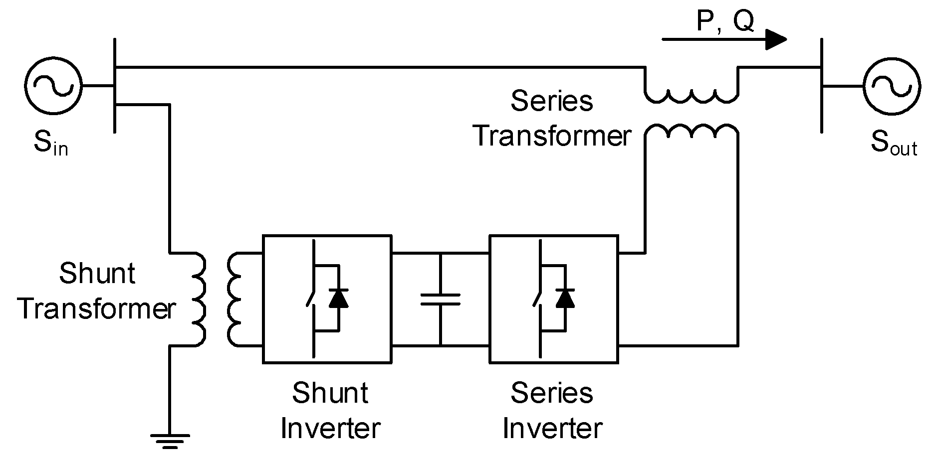
A conventional UPFC is a combination of a STATCOM and SSSC, which share a DC link capacitor.
Figure 1 shows the configuration of the conventional UPFC system, which comprises two transformers and two power converters. Among the power converters, the series inverter controls the power flow and improves the dynamic stability in the transient state by controlling the voltages in the steady state. In contrast, the parallel inverter compensates the reactive power and supplies the power required for the series inverter. However, the series transformer and inverter are bulky and expensive because a large amount of transmission-line current flows through them [
23]. Therefore, the use of conventional UPFCs has been limited, although their performance is outstanding. Consequently, the demand for a smaller, lower-cost topology has increased.
To mitigate the disadvantages and exploit the merits of UPFCs, various topologies have been proposed, such as a distributed power flow controller (DPFC) [
24], UPFC based on a matrix converter (MC-UPFC) [
25], and transformerless UPFC based on a multilevel inverter [
6]. However, because of the low-rating converters, the volume of the DPFC may be larger than that of the conventional UPFC. In addition, if the MC-UPFC system is defective, the power grid system might be unstable because of the short circuit current and surge voltage. Transformerless UPFCs based on a multilevel inverter require several switches and connection lines, which make the system complex. As a result, a smaller, lower-cost, and simpler UPFC topology is required.
This paper proposes a new UPFC topology. The single phase of the system consists of a single-phase transformer, interface filter, and power converter module. An N:2 transformer with a center tap is used as single-phase transformer and is connected using an autotransformer structure. The power converter module includes full- and half-bridge converters. A three-phase UPFC system can be simply implemented using three devices.
Using the proposed topology, the number of transformers decreases from two to one compared with the conventional topology. Owing to the merits of having an autotransformer structure, the power rating of the transformer can be significantly reduced. By using a transformer with a high turns ratio, the voltage rating of the switches, and thus the manufacturing costs, can be reduced. In addition, the power converter module requires only three legs. One leg is used for an output half-bridge inverter and the others are utilized for an input full-bridge converter. Established inverter techniques can be applied to control the proposed topology. In general, for a large capacity system, a three-phase system consists of three single-phase systems for convenience of manufacturing. With the proposed system, because each phase of the power converter module is manufactured separately, the insulation between modules is easy.
On the other hand, since the voltage of the power converter module is floated from the ground, insulations should be carefully considered. However, by applying the insulation method used for power converters in HVDC or FACTS, the proposed topology could be insulated in a similar manner. In those applications, the power converters are installed away from the ground and walls of buildings, and they are hung on the ceiling of the building and fixed.
This paper was previously presented at the 10th International Conference on Power Electronics (ICPE 2019) and ECCE Asia; in the present publication, more details and a discussion of the results are provided [
26].
3. Verification Results
To verify the proposed system, simulations and experiments were performed. The verification results in this section were intended to demonstrate that the proposed system is as capable of power flow control as the conventional one.
3.1. Simulations
The proposed UPFC topology, as shown in
Figure 2, was simulated using the parameters listed in
Table 1.
Figure 6 shows the simulation model. MATLAB and PLECS were the software used for simulations. Although only the proposed single-phase system was simulated, a three-phase system can be implemented using three single-phase systems.
In the simulation, the grid voltage was assumed to be 345 kV. The transmission line was assumed to be 50 km, such that the line impedance was modeled as 3 + j9.5 Ω, considering the impedance per length of the transmission line [
31]. The turns ratio of the transformer was designed to be 78:2.
As the power converter module, a two-level topology was used for simplicity and its switching frequency was set to 5 kHz. However, various types of well-developed topologies can be adopted, such as multilevel inverters and modular multilevel converters. The nominal DC link voltage was set to 10 kV, which is much smaller than the grid voltage. A coupled inductor structure was used as an interface filter. The common and differential modes were set to 0.2 and 1.5 mH, respectively.
Figure 7 shows the simulation results from 0 to 12 s. The switching of the power converter module was started after 1 s, and the differential mode current was set to zero. After 1.5 s, the DC link voltage was controlled at a nominal value. After 3 and 4 s, the active and reactive power references of three-phase system were increased to 50 MW and 40 MVar, respectively. After 5 and 6 s, respectively, they were both reduced to zero. After 7 and 8 s, they were changed to −50 MW and −40 MVar, respectively. After 9 and 10 s, respectively, they were changed to zero. In the simulations, the references ware changed using a slope of 500 MVA/s.
Figure 7a shows the performance of the DC link voltage control. Because the regulator was designed as an IP controller, an overshoot phenomenon was not observed, and the voltage could be controlled well.
Figure 7b shows the active and reactive powers of the transmission line and their references. The active and reactive power were controlled as references at steady states. The transient response was stable because the references were changed as a ramp function, using a slope of 500 MVA/s. There were minimal coupling phenomena, and, in reality, coupling can be mitigated because the references are changed using appropriate slopes. The active and reactive powers were controlled well according to their references.
Figure 7c,d shows the magnitude and phase of the injection voltage, respectively, which were used to control the power flow. By synthesizing an appropriate injection voltage, the performance of the power flow control could be verified.
Figure 8 shows the transient waveforms of
V1,
Vin, and
I after the change of the power reference. The signals of
Vin and
I are magnified for clarity.
Figure 8a shows the waveforms of
V1,
Vin, and
I after the power reference was changed from 0 to 50 + j0 MVA. Because the phases of
V1 and
I were the same, it is possible to confirm that only active power was delivered as the power reference.
Figure 8b–d shows the same waveforms as
Figure 8a.
Figure 8b shows the waveforms of
V1,
Vin, and
I after the power reference was changed from 50 MW to 50 + j40 MVA. Before 4 s, because the phases of
V1 and
I were the same, it is possible to confirm that only active power was delivered. However, after 4 s, the magnitude of
I was increased and the phase of
I was changed. At the steady state, the phase difference between
V1 and
I was about 38 degrees. Therefore, it is possible to confirm that active power and reactive power were delivered as references.
Figure 8c shows the same waveform after the power reference was changed from 50+j40 MVA to 40 Mvar. Before 4 s, the phase difference between
V1 and
I was about 38 degrees. However, after 5 s, the magnitude of
I was decreased and the phase difference between
V1 and
I was about 90 degrees at steady state. So, it is possible to confirm that only reactive power was delivered as the power reference.
Figure 8d shows the same waveform after the power reference was changed from 40 Mvar to 0 VA. Before 6 s, the phase difference between
V1 and
I was about 90 degrees; however, after 6 s, at steady state, the magnitude of
I was decreased to zero. So, the proposed system delivered no power as a reference.
With the proposed UPFC topology, the complex powers could be regulated according to the references, which verifies the proposed system.
3.2. Experiments
Laboratory-scale experiments on the proposed topology were performed using the parameters listed in
Table 2.
Figure 9a,b shows the configuration of the experimental setup and equivalent circuit, respectively. Two three-phase Δ-Y transformers were used to emulate the grid voltages
V1 and
V2. These voltages were set to 220 V in the experiments.
The turns ratio of the transformer in the laboratory-scale UPFC system was 5:2. Two single-phase 5:1 transformers, which were held in the laboratory, were used to implement a 5:2 transformer with a center tap. They were connected using an autotransformer structure. Because the turn ratio of the transformers was lower than that of the simulations, the nominal DC link voltage was set to 150 V, which is a relatively large value.
A coupled inductor was used for the interface filter of the proposed system. The common and differential mode inductances were 0.5 and 6 mH, respectively. To emulate the line impedance, a 4 mH inductor was used.
A two-level topology was used as a power converter module for simplicity; its switching frequency was set to 5 kHz. The capacitance of the DC link capacitor was 2.8 mF.
Figure 10 shows the experimental results.
Figure 10a shows the performance of the DC link voltage control. The voltage of the DC link was controlled well according to the reference of 150 V.
Figure 10b shows the performances of the DC link voltage and differential mode current controls after the DC link voltage control was started. The differential mode current was regulated well using the PR controller. In addition, by controlling the differential mode current, the DC link voltage could be controlled well.
Figure 11 shows the experimental results. The waveforms of
V1,
Vin*,
V1 +
Vin, and I are shown. In this study,
V1 represents the grid voltage measured by a differential probe, as shown in
Figure 2, and
V1 +
Vin is the output voltage of the power converter module measured by a differential probe. In addition,
Vin* is the injection voltage reference according to the complex power references, which was scattered by a digital to analog converter (DAC). Owing to the switching of the power converter module to the actual voltage,
Vin shows PWM waveforms, whose magnitude is the same as that of the DC link voltage. Therefore, the voltage of
V1 +
Vin is the sum of
V1 and the PWM waveform of
Vin. The parameter I represents the line current measured by the current sensor. Therefore, switching ripples were only included in
V1 +
Vin.
Figure 11a shows the transient waveforms of
V1,
Vin, and
I after the single-phase complex power reference was changed from 0 to 1 + j0 kVA. In the experiments, the reference was changed using a slope of 20 kVA/s. Because of the appropriate slope, the experimental results show no coupling phenomenon, which leads to overshoot and distortions. Because the phases of
V1 and
I are the same and the magnitude of the line current is ~6.5 A, it can be confirmed that the UPFC only delivers active power according to the complex power reference.
Figure 11b–d shows the same waveform as
Figure 11a.
Figure 11b shows the transient waveforms of
V1,
Vin, and
I after the single-phase complex power reference was changed from 1 + j0 kVA to 1 + j1 kVA. Because the phase difference between of
V1 and
I was the same at almost 45 degrees in steady state, it is possible to confirm that the complex power was delivered as a reference.
Figure 11c shows the transient waveforms of
V1,
Vin, and
I after the single-phase complex power reference was changed from 1+j1 kVA to 1 kvar. Because the phase difference between
V1 and
I was the same at almost 90 degrees in steady state, it is possible to confirm that only reactive power was delivered as the reference. At steady state, the magnitude of
I was decreased to zero. So, the proposed system delivered no power as reference.
Figure 11d shows the transient waveforms of
V1,
Vin, and
I after the single-phase complex power reference was changed from 1 kvar to 0 kVA. All figures in
Figure 11 show that the complex power could be controlled well according to its reference, similar to the simulation results. These experimental results confirm the validity of the proposed UPFC topology.
With the simulations and experiments, it is hard to verify the cost savings and smaller installation spaces, however, the advantages of the proposed system can be inferred due to the fact that the proposed system can increase the turn ratio of the transformer.
4. Conclusions
Conventional power grid systems have the following problems that reduce their efficiencies: (1) low utilization of transmission lines and (2) load imbalance due to limited control capabilities. One solution to solve these problems is to use FACTS devices. Among them, UPFC, which can control the power flow of the transmission system, is the most capable FACTS device. A conventional UPFC system is a combination of a STATCOM and SSSC, which share a DC link capacitor, and comprises two transformers and two power converters, which are bulky and expensive. Consequently, although their performance is outstanding, the use of conventional UPFCs has been limited because of these shortcomings.
To mitigate the disadvantages and exploit the merits of UPFCs, this paper proposes a new UPFC topology based on an autotransformer structure. A single phase of the proposed UPFC system consists of an N:2 transformer with a center tap at the low-voltage side, a power converter module, and an interface filter. A three-phase of UPFC system can be simply implemented using three devices. A power converter module consists of two parts: (1) an input full-bridge converter and (2) output half-bridge inverter. By controlling the differential current among input currents, the input full-bridge converter controls the DC link voltage for the output half-bridge inverter. By synthesizing an appropriate injection voltage, the half-bridge inverter controls the power flow of the transmission line. The effectiveness of the proposed topology has been verified through simulations and experiments.
Based on the proposed system, only one single-phase transformer is required per phase, which means the number of the single-phase transformer is halved compared to the conventional one. With the proposed system, because each phase of the power converter module is manufactured separately, the insulation between power converter modules is easier. In addition, by using a transformer with a high turn ratio, the voltage rating of the power converter module can be significantly reduced. Consequently, the manufacturing costs and installation space required can be reduced compared with those of the conventional UPFC topology. Based on these advantages, the utilization of the UPFC with the proposed topology can be increased, which could be useful for the implementation of smart grids.


