Article

3D Printing Using a 60 GHz Millimeter Wave Segmented Parabolic Reflective Curved Antenna

1
College of Electrical Engineering, Zhejiang University, Hangzhou 310027, China
2
Key Laboratory of RF Circuits and Systems, Ministry of Education of China, Hangzhou Dianzi University, Hangzhou 310018, China
*
Author to whom correspondence should be addressed.
Electronics 2019, 8(2), 203; https://doi.org/10.3390/electronics8020203
Submission received: 16 January 2019 / Revised: 29 January 2019 / Accepted: 29 January 2019 / Published: 11 February 2019
(This article belongs to the Special Issue Millimeter-Wave (mmWave) Communications)

Abstract

:
This paper proposes a segmented parabolic curved antenna, which can be used in the base station of a 60 GHz millimeter wave communication system, with an oblique Yagi antenna as a feed. By analyzing the reflection and multi-path interference cancellation phenomenon when the main lobe of the Yagi antenna is reflected, the problem of main lobe splitting is solved. 3D printing technology relying on PLA (polylactic acid) granule raw materials was used to make the coaxial connector bracket and segmented parabolic surface. The reflective surface was vacuum coated (via aluminum evaporation) with low-loss aluminum. The manufacturing method is environmentally friendly and the structure was printed with 0.1 mm accuracy based on large-scale commercial applications at a low cost. The experimental results show that the reflector antenna proposed in this paper achieves a high gain of nearly 20 dBi in 57–64 GHz frequency band and ensures that the main lobe does not split.

1. Introduction

With the rapid development of broadband technology, there is a large potential market demand for wireless communication with 1 Gbit capacity per second. This has led to 60 GHz millimeter wave communication becoming a research hotspot. High gain, a wide bandwidth, no main-lobe splitting, easy integration and low loss are key indicators for 60 GHz millimeter wave base station antennas. On the other hand, the silicon-based system-on-chip system concentrates the on-chip antenna and the on-chip active modules in the same chip, which is advantageous for mass production. However, due to the loss of the silicon substrate, the conventional on-chip antenna cannot meet the requirements to be a base station antenna. The substrate integrated antenna [1,2,3,4] and the microstrip antenna [5] can meet the above requirements but to achieve high gain, the above two antennas need to adopt an array combination and the feed network is very complicated. This also increases the profile of the antenna, which means more corrosive liquid in manufacturing, causing consequent environmental pollution problems. Therefore, the use of an on-chip reflective antenna is alternative choice. In the literature [6], multiple planar dipole antennas are used as feeds and concentric circles of different radii are formed by hollowing out the layers of the multilayer substrate. The cross section is approximately parabolic and has a directional beam scanning function but its bandwidth is only 4 GHz, which is unable to meet the requirements of millimeter wave broadband communication. In contrast, PLA plastics used in plastic powder additive manufacturing technology (i.e., 3D printing technology) are naturally degradable and environmentally friendly, while substrates made by 3D printing can be formed by vacuum plating to form reflective surfaces for antennas. The 3D printing accuracy of existing commercial applications can reach a range of 0.1 mm; with low cost, which is very suitable for the millimeter wave frequency band. Compared with the traditional metal reflective surface, the plastic printing plus technology vacuum plating can reduce the weight by 80% and its structure is light. While studies reflected in the literature [7,8,9] made a useful attempt, the feed antenna used for a waveguide interface and cannot be seamlessly integrated with active modules. In view of the above problems, this paper adopts 3D printing technology to realize the antenna reflection surface and utilize the planar Yagi antenna as the feed source, hence achieving seamless integration of the on-chip antenna and the active module. Moreover, in order to meet the key indicators of the above 60 GHz millimeter wave base station antenna, this paper adopts the oblique reflection surface structure, which eliminates the shadowing effect of the feed and eliminates the main lobe splitting caused by multipath interference cancellation. The performance of the antenna is improved effectively. Through optimization, the antenna proposed in this paper satisfies the above indicators during actual measurement and is expected to become a new generation of on-chip integrated antennas for base stations.

2. Antenna Design

2.1. Parabolic Feed Antenna Design

The Yagi-Uda antenna [10] itself is composed of end-fire arrays with high gain, wide bandwidth and low cross-polarization. The planar Yagi-Uda antenna is extremely suitable for microwave and millimeter wave applications due to its high gain, low loss, high radiation efficiency and ease of fabrication [10]. Therefore, it was chosen as the feed for the reflector antenna in this paper. The planar Yagi-Uda antenna includes the extended ground wire on the PCB as a reflector and a planar printed dipole as the driver, both are printed on both sides of the PCB. All the four directors of Yagi antenna were printed paralleled with the dipole on the upper surface of PCB. The initial design was based on empirical data from free space and then scaled down to the equivalent dielectric constant. The microstrip, the dipole and the directors were connected by planar printing balun to ensure sufficient bandwidth. However, this design also created a high level of cross-polarization. Therefore, the electro-magnetic field numerical analysis method (HFSS) was used for analysis and adjustment. The method was used to increase the shape of the saw ruler to eliminate surface waves and reduce cross-polarization. As shown in reference [10], the designed Yagi antenna has four directors. The substrate is Rogers 5880 (dielectric constant of 2.2) and the substrate thickness 0.254 mm. Figure 1 shows the connector and connector bracket of the antenna.
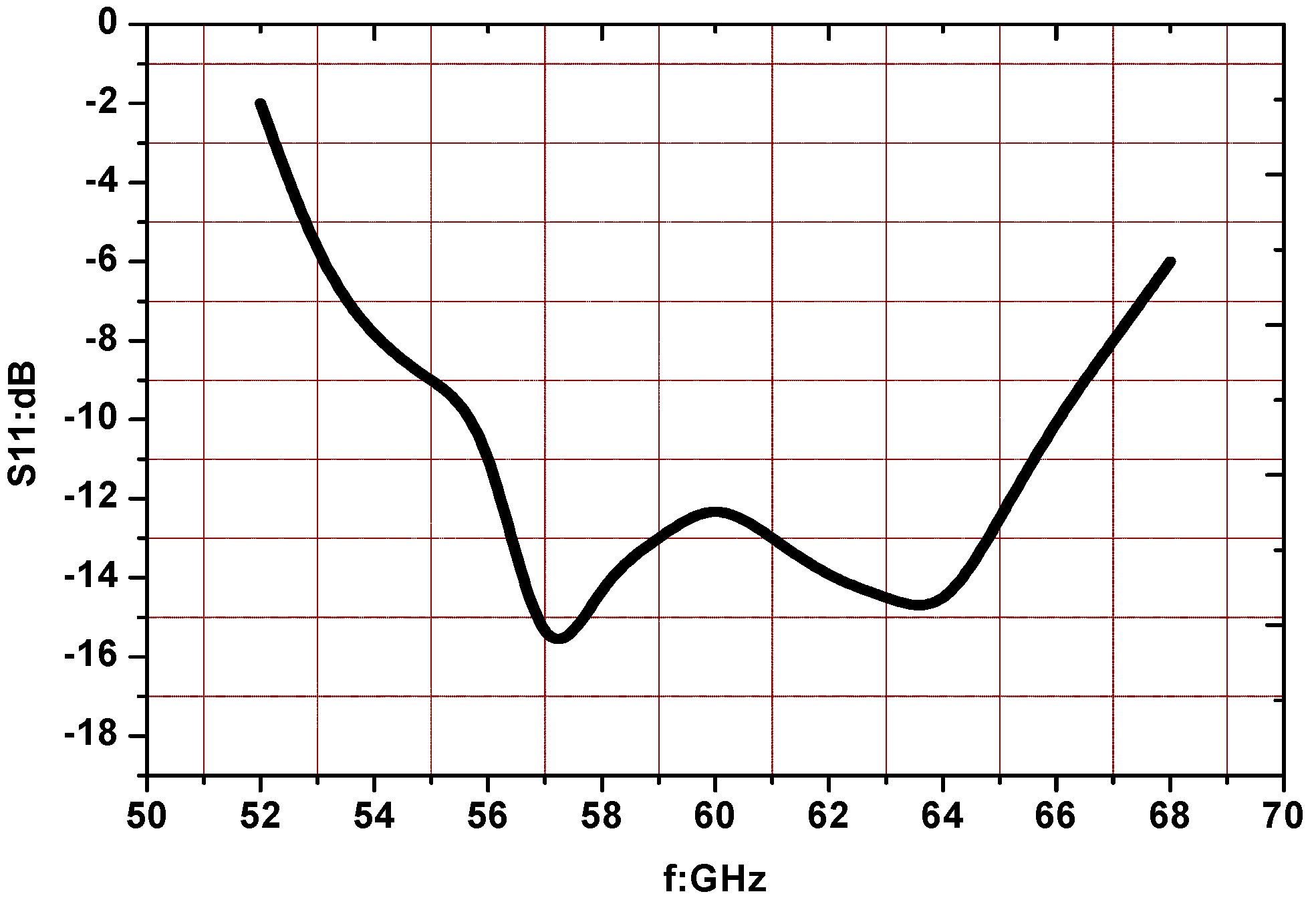
The Yagi antenna has a −10 dB bandwidth of 56–67 GHz which is shown in Figure 2. It can demonstrate a low sidelobe radiation pattern with a maximum gain of 9.3 dBi [10]. It was used as a parabolic antenna feed, supplemented by a 3D printed support frame with an accuracy of 0.1 mm, hence achieving a seamless connection of the transfer interface. In the 60 GHz millimeter wave environment, the tilt of the electrical scale by 1 mm to 2 mm will bring a large error. Therefore, the support bracket was designed to avoid the tilt of the connector due to gravity and the system accuracy was improved.

2.2. Parabolic Antenna Structure

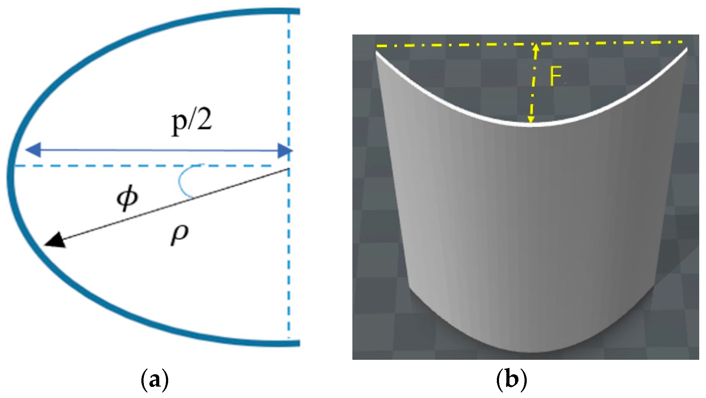
The parabolic antenna shown in Figure 3a affects the antenna performance by obscuring the reflected parallel electro-magnetic waves due to the size of the feed at the parabolic focus. The cylindrical paraboloid shown in Figure 3b was used to allow the antenna feed to be incident obliquely and the reflected parallel electromagnetic waves do not create a shadowing effect. In order to obtain the parabolic profile of the reflecting cylinder, the paraboloid profile is satisfied as follows:
ρ = 2 p 1 + c o s ϕ = p sec 2 ( ϕ 2 )
where ρ represents the distance from the center of the parabola to the curve in polar coordinates, p is double the focal distance F as shown in Figure 3 and ϕ is the angle in polar coordinates.
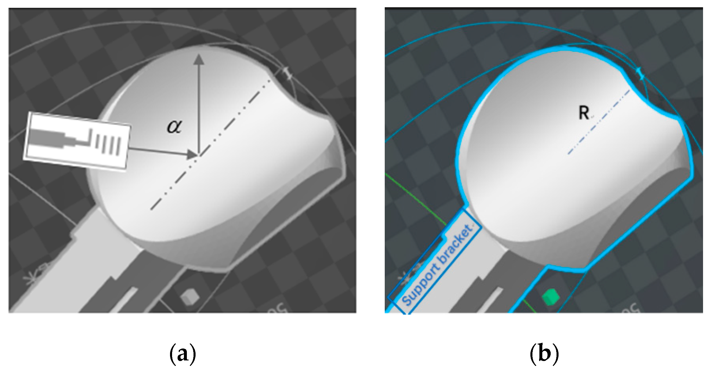
In order to make the antenna sidelobe smaller, the angle α between the reflected wave and the incident wave was 120° as shown in Figure 4a after optimization. The focal length F of the parabolic was 7 mm and p was 14 mm as shown in Figure 3a. The parabolic profile has a profile radius R of 20 mm. In the optimization process, we choose the angle α between the reflected wave and the incident wave to be 100°, 120° and 140°, respectively. The radiation patterns in Figure 5 are obtained by HFSS simulation.
The parabolic cross section is shown in Figure 3a and the cylindrical parabolic antenna is shown in Figure 6a. The Yagi antenna is placed horizontally and perpendicular to the support column and the angle between the paraboloid and the support column is 60° according to α equal to 120°. The paraboloid was cut with a spherical shape to make the contour more regular.
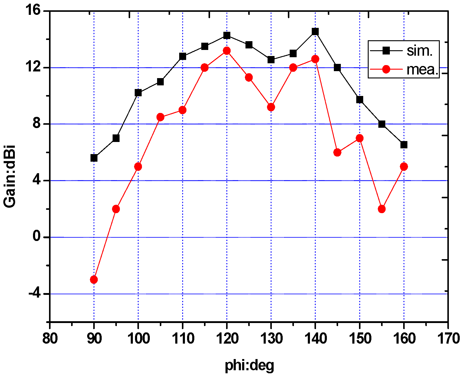
The main lobe of the Yagi antenna has a certain narrow −3 dB width. The optical path of the longitudinal section is shown in Figure 6. As illustrated in Figure 6b, the optical path difference between optical paths 1 and optical path 2 is much shorter than that of optical path 3 and optical path 4. Therefore, there is always one direction and the optical path difference of the two optical paths is half the wavelength, which causes the main lobe to be split due to interference. Both the simulation and measurement result of the main lobe splitting are shown in Figure 7. The measurement splitting is more obvious and while the simulation splitting has a 2 dB recess.

2.3. Parabolic Curved Antenna

In order to solve the afore-mentioned main lobe splitting problem, the reference [11] used the reflective surface of the longitudinal parabola profile. As shown in Figure 8a, at this time, the reflected rays are almost parallel and the interference phenomenon can be effectively avoided. The paraboloid was also modified from the original cylinder, as shown in Figure 6a, to an orthogonal parabolic surface, as shown in Figure 8b. The distance between the four vertices of the paraboloid and the center of the cutting sphere is R and R is contour radius. Moreover, the distance between the top and bottom vertices on the same side is 1.8 R.
By calculating the formula based on the parabolic antenna gain:
G = η A 4 π S / λ 2
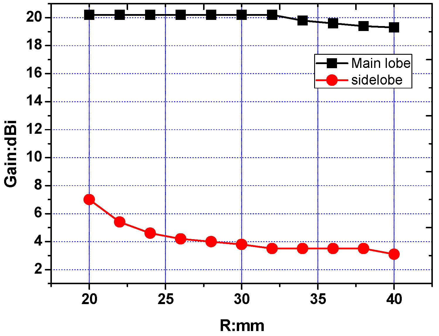
Here η A is the aperture efficiency of the parabolic antenna and it includes spillover efficiency η s and aperture taper efficiency η t . S is the physical area of the antenna aperture and λ is the wavelength. As the flare angle increases with contour radius R, η s increases correspondingly. Since here the gain value decreases with R as shown in Figure 9 (when R = 20, 30, 40, the gain pattern can be referred to in Figure 10), it indicates that the irradiation becomes non-uniform due to decrease of the aperture taper efficiency η t . When the contour radius is too small, the side lobe level become higher due to the diffraction effect of the edge or small spillover efficiency η s . The highest side-lobe according to Figure 9 is 7 dBi, corresponding to a maximum main lobe gain of 20 dBi. Regarding optimization, the optimum profile radius was 32 mm (3.7 dBi for the side lobes and 20 dBi for the main lobes). Considering that the feed will deviate from the vertical direction of support column due to alignment error, the minimum distance between the contour edge and the projection point of the feed center on the paraboloid was guaranteed to be 32mm and the contour radius was set at 40mm. Simultaneously, the maximum gain is 19.3 dBi at 61 GHz frequency.

2.4. Segmented Parabolic Surface Antenna

The parabola converted the ideal point source at the focus into parallel rays. However, for a given −3 dB beam width feed like the Yagi antenna, it was viewed as a collection of multipoint sources at different locations. Therefore, the parabola needs to be corrected in order to integrate the point sources at different locations to obtain the optimal parallel light generation effect. The parabolic equation is:
ρ = 2 p 1 + c o s ϕ
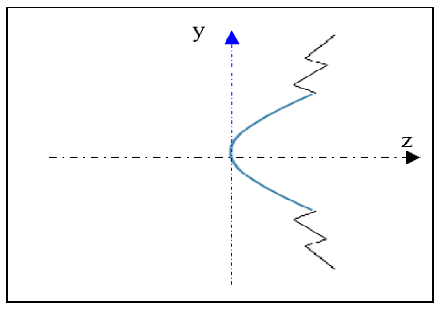
A segmentation combination of the parabolic equation was made using different parameter measures for p, which is similar to what was done in reference [12]. Optimized using the HFSS simulation, the combined parabolic equation is:
{ ρ = 2 p 1 1 + c o s ϕ ; ϕ [ π 6 , π 6 ] ρ = 2 p 2 1 + c o s ϕ ; ϕ [ 7 π 36 , π 6 ] [ π 6 , 7 π 36 ] ρ = 2 p 3 1 + c o s ϕ ; ϕ [ π 4 , 7 π 36 ] [ 7 π 36 , π 4 ]
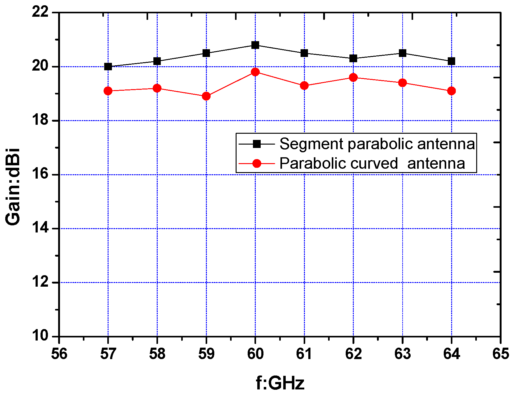
The value of p 1 , p 2 , p 3 are 12, 14 and 16 mm respectively. At 61 GHz, the gain of the segmented combined parabolic surface was 1 dB higher than the gain of the parabolic surface, with a gain of 20.5 dBi. As can be seen from Figure 11, the gain value of each frequency point at 57–64 GHz increased stably by 1 dB.

3. Simulation and Experimental Results

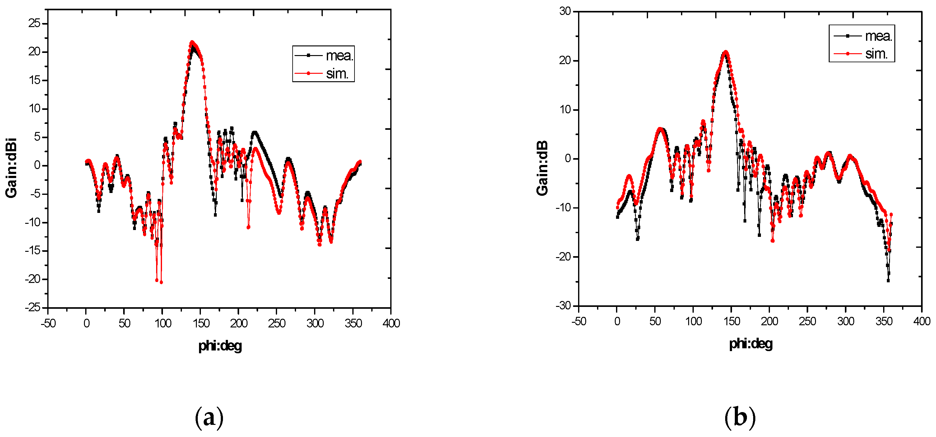
The three-dimensional structure of the segmented parabolic surface is shown in the Figure 12 above which Figure 12c shows the antenna in the microwave anechoic chamber, and its one-dimensional graph is shown in Figure 13. In Figure 14, two curves represent the simulation result and the measured result respectively. At 61 GHz, the measured gain was 20 dBi and the first side lobes reached 6 dBi, which is 14 dB lower than the main lobe. At 64 GHz, the first side lobes reached 7 dBi, which is 13 dB lower than the main lobe.

4. Conclusions

An antenna system using a 3D printed vacuum-plated parabolic surface and a planar Yagi antenna as a feed can be seamlessly integrated as planar antenna with on-chip millimeter active module. The improved reflective surface design as shown in Figure 8, by using a parabolic surface, gain was not only improved by 5 dB but the gain value reached 19 dBi. Also, it improved the main-lobe splitting as shown in Figure 7. Moreover, the segmented combined parabolic surface as shown in Figure 12 was further improved and the gain value reached 20 dBi in the 57–64 GHz band. Compared with the traditional metal reflective surface, the plastic printing plus vacuum plating parabolic can reduce the weight by 80% and it is easy fabricated, low cost and environment friendly.

Author Contributions

B.C. completed the methodology; B.C. and Y.L. completed the design; B.C. wrote the paper. L.S. reviewed the paper.

Funding

This research was funded by the Natural Science Foundation of Zhejiang Provincial education department under Grant Y201636542.

Acknowledgments

The authors would like to thank Lei Liu for his supports in the simulations.

Conflicts of Interest

The authors declare no conflict of interest.

References

  1. Yang, T.Y.; Wei, H.; Zhang, Y. Wideband millimeter-wave substrate integrated waveguide cavity-backed rectangular patch antenna. IEEE Antennas Wirel. Propag. Lett. 2014, 13, 205–208. [Google Scholar]
  2. Li, M.J.; Luk, K.M. A low-profile unidirectional printed antenna for millimeter-wave applications. IEEE Trans. Antennas Propag. 2013, 62, 1232–1237. [Google Scholar]
  3. Cheng, S.; Yousef, H.; Kratz, H. 79 GHz slot antennas based on substrate integrated waveguides (SIW) in a flexible printed circuit board. IEEE Trans. Antennas Propag. 2009, 57, 64–71. [Google Scholar]
  4. Guntupalli, A.B.; Wu, K. 45° linearly polarized high-gain antenna array for 60-GHz radio. IEEE Antennas Wirel. Propag. Lett. 2014, 13, 384–387. [Google Scholar]
  5. Lamminen, A.E.I.; Saily, J.; Vimpari, A.R. 60-GHz patch antennas and arrays on LTCC with embedded-cavity substrates. IEEE Trans Antennas Propag. 2008, 56, 2865–2874. [Google Scholar]
  6. Hosseini, A.; Kabiri, S.; De Flaviis, F. V-Band High-Gain Printed Quasi-Parabolic Reflector Antenna with Beam-Steering. IEEE Trans. Antennas Propag. 2017, 65, 589–591. [Google Scholar]
  7. D’Auria, M.; Otter, W.J.; Hazell, J.; Gillatt, B.T.; Long-Collins, C.; Ridler, N.M.; Lucyszyn, S. 3-D printed metal-pipe rectangular waveguides. IEEE Trans. Compon. Packag. Manuf. Technol. 2015, 5, 1339–1349. [Google Scholar]
  8. Nguyen, N.T.; Delhote, N.; Ettorre, M.; Baillargeat, D.; Coq, L.; Sauleau, R. Design and characterization of 60-GHz integrated lens antennas fabricated through ceramic stereolithography. IEEE Trans. Antennas Propag. 2010, 58, 2757–2762. [Google Scholar]
  9. Nayeri, P.; Liang, M.; Sabory-Garcı, R.A.; Tuo, M.; Yang, F.; Gehm, M.; Xin, H.; Elsherbeni, A.Z. 3D printed dielectric reflectarrays: Low-cost highgain antennas at sub-millimeter waves. IEEE Trans. Antennas Propag. 2014, 62, 2000–2008. [Google Scholar]
  10. Alhalabi, R.A.; Chiou, Y.C.; Rebeiz, G.M. Self-shielded high-efficiency Yagi-Uda antennas for 60 GHz communications. IEEE Trans. Antennas Propag. 2011, 59, 742–750. [Google Scholar]
  11. Xie, Z.M.; Wang, L.X.; Pei, S.S. Linear array feeding caustics parabolic curved antenna for space power synthesis. Chin. J. Radio Sci. 2012, 2, 209–214. [Google Scholar]
  12. Rao, S.; Tang, M.Q. Stepped-reflector antenna for dual-band multiple beam satellite communications payloads. IEEE Trans. Antennas Propag. 2006, 54, 801–811. [Google Scholar]
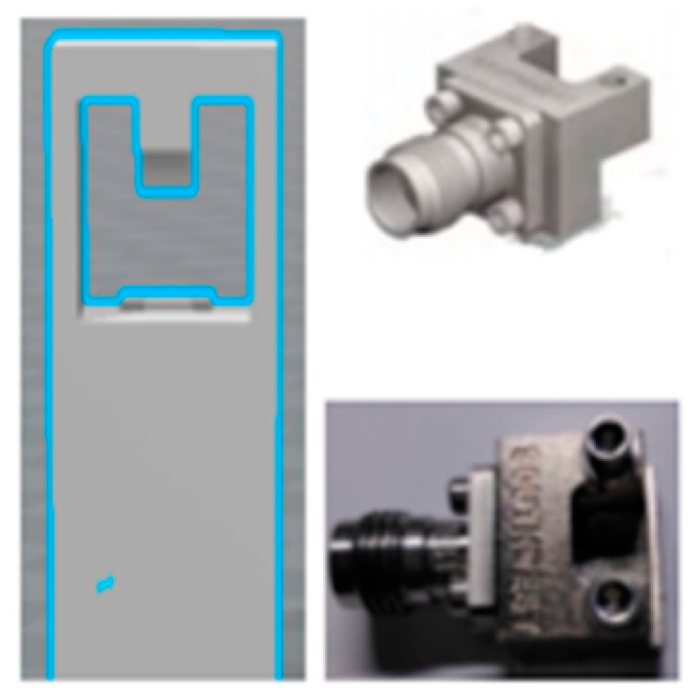
Figure 1. Connector Bracket and connector.
Electronics 08 00203 g001
Figure 2. S parameter of Yagi-Uda antenna.
Electronics 08 00203 g002
Figure 3. Parabolic reflector. (a) Parabolic curve (b) 3D structure.
Electronics 08 00203 g003
Figure 4. Cylindrical parabolic antenna (a) Angle α (b) Profile radius R.
Electronics 08 00203 g004
Figure 5. Radiation patterns with different angle α measurements at 59 GHz.
Electronics 08 00203 g005
Figure 6. Optical paths in the parabolic reflector (a) 3D diagram (b) 2D diagram.
Electronics 08 00203 g006
Figure 7. Simulation and test data for the cylindrical reflector antenna at 59 GHz.
Electronics 08 00203 g007
Figure 8. Rays on the longitudinal parabola (a) 2D diagram (b) 3D diagram.
Electronics 08 00203 g008
Figure 9. Gain values of the main and sidelobes at different contour radii. at 59 GHz.
Electronics 08 00203 g009
Figure 10. Gain pattern with different parabolic surface radii. at 59 GHz.
Electronics 08 00203 g010
Figure 11. Comparison between Segment parabolic and Parabolic curved antenna.
Electronics 08 00203 g011
Figure 12. (a) Three-dimensional structure of the segmented parabolic surface (b) Rays on segmented parabolic surface (c) The segmented parabolic surface in the microwave anechoic chamber.
Electronics 08 00203 g012
Figure 13. Segment parabolic curve antenna.
Electronics 08 00203 g013
Figure 14. Simulation and test gain patterns at frequencies of (a) 61 and (b) 64 GHz.
Electronics 08 00203 g014