Article

A Nonisolated Three-Port DC–DC Converter with Continuous Input and Output Currents Based on Cuk Topology for PV/Fuel Cell Applications

by
Balaji Chandrasekar
1,*,
Chellammal Nallaperumal
1 and
Subranshu Sekhar Dash
2
1
Department of Electrical and Electronics Engineering, SRM IST, Kattankulathur, Chennai, Tamilnadu PIN-603203, India
2
Department of Electrical and Electronics Engineering, Government College of Engineering, Keonjhar, Odisha PIN-758002, India
*
Author to whom correspondence should be addressed.
Electronics 2019, 8(2), 214; https://doi.org/10.3390/electronics8020214
Submission received: 14 January 2019 / Revised: 6 February 2019 / Accepted: 10 February 2019 / Published: 15 February 2019
(This article belongs to the Special Issue Advanced Power Conversion Technologies)

Abstract

:
A nonisolated three-port DC–DC converter based on Cuk topology (NI-TPC) to handle the renewable sources (RS) is proposed in this paper. This converter includes two unidirectional input ports accommodating both a fuel cell (FC) and photovoltaic (PV) cell; and one output port with DC load. Due to the inductors at all the ports, it claims the advantage of continuous input and output currents. Additionally, it uses less number of switches, diodes and inductors compared with conventional ‘n-1’ separate Cuk converters. Synthesis procedure for a generalized n-port DC–DC structure is explained. The derivation law based on conventional Cuk converter, operating principle, design calculation, and analysis are presented in detail, and then the analysis is validated through simulation and a 100W prototype, verifying the performance of the proposed NI-TPC converter.

1. Introduction

Fast and society-threatening global warming and health hazards due to the combustion of fossil fuels have triggered the research and development of more efficient and cleaner renewable sources (RS) namely solar, wind, fuel cell etc. Many DC–DC converters with a single inductor, for example, buck and boost converters and two inductor converters, such as Sepic, Cuk, and zeta converters, have been used to connect RS and load [1,2]. However, the stochastic and time-varying characteristics of these sources and unpredictable demand at load side necessitate the backup source for continuous power flow to the load. This condition forces the system to have at least two input ports; one for RS and another for a backup source such as fuel cell/wind/battery.
In the recent past, new converter topologies called multiport converters (MPC) have been proposed to integrate these RS, which ensure the continuous power flow to the load. The structure of conventional and MPC system is shown in Figure 1. The MPCs enhance the utilization of power sources based on their V–I characteristics, availability and cost [3]. Multiport converters (MPC) which claim the advantage of component sharing are acknowledged as one of the promising topologies to integrate the RS to cater the future energy generation requirements. Moreover, compact structure and lesser conversion stages are the reasons to adopt MPC for numerous applications such as hybrid power system [4], renewable energy integration [5], hybrid vehicles [6], aerospace applications, and uninterrupted power supplies. This MPC, in particular, the three-port converter (TPC) can be divided into three groups: (1) the isolated DC–DC converter; (2) semi-isolated DC–DC converter; and (3) nonisolated converter topologies. The isolated TPC uses a transformer with a high-frequency to provide magnetic coupling and electrical isolation between the source and load [6,7,8]; partially isolated converters use a common DC bus along with magnetic coupling [9]. A nonisolated TPC uses common DC bus and finds applications where the isolation is not needed between the ports [10,11,12].
TPCs can be configured in two topologies based on the nature of the input sources: series and parallel. In the series topology, the output voltage regulation becomes challenging if one of the input sources reduces (e.g., in PV shading condition) [13]. Assumptions and conditions to design the converters with multiple input–single output (MISO) from the conventional single input–single output (SISO) structures are explained [14]. The systematic way of synthesizing MISO converters is detailed in Reference [15]. Topology generation methods and principles for developing a family of NI-TPC are proposed [16]. These TPCs are developed by introducing a SISO model in an existing dual input or two output converters. In Reference [17], an approach to systematically derive MPCs with DC link inductor concept and with two input and two output converters is proposed. This procedure has developed numerous TPC topologies. A novel nonisolated TPC with single inductor is proposed for RS [18]. This converter features the integration and control of bidirectional load, compactness, single stage power conversion between any two ports, and seven possible operational modes. The design of a NI-TPC using one switch for a standalone PV power system integrating energy storage is proposed in Reference [19]. A synchronous switch with a pair of diodes has been utilized instead of two individual switches. However, the converters in both the stages must operate synchronously. The inherent buck–boost characteristics of the Cuk converter provide flexibility for standalone and grid-tied applications when the output voltage required is more or less than the input voltage. Continuous current at the input and output ports and the identical switching voltage waveforms appearing across the inductors are the salient features of the Cuk converter [20]. New topologies with high voltage ratio have been proposed using Cuk converter in Reference [21] for renewable power applications. In Reference [9], A TPC is presented by integrating a Cuk converter with bidirectional power flow and a full-bridge (FB) rectifier circuit for renewable energy applications. It used a transformer with high frequency. This converter consists of two nonisolated and one isolated ports. A nonisolated DC–DC TPC using integrated boost-cuk topology with high voltage gain is proposed [22]. An isolated TPC depending on Cuk converter is presented in Reference [23] by incorporating the inductor and transformers on a single core. Three winding transformer used in the above converter increases the size. Moreover, it uses more number of switches. The three-port Cuk converter to solve the zero-ripple problem is presented by designing a single integrated magnetic core having all the magnetics on it [24]. Methods based on circuit theory and the structure of the core are used to analyze the ripples. However, these converters are the isolated type and use bulky transformers and inductors. In Reference [25], a DC–DC converter combining a SEPIC and Cuk converter is proposed for bipolar DC microgrid applications. A single switch shared by both converters is an added advantage. However, the number of power components is greater.
However, the TPCs mentioned above fail to provide a high voltage conversion ratio and continuous current at all the ports.
The outstanding features of the proposed converter are
  • Both the input ports share common output inductor, hence minimizing the component count.
  • Continuous current with less ripple in all the ports (the input and output ports).
  • Delivered power from each input can be independently controlled
  • Buck–boost output voltages can be obtained.
To the best of the author’s knowledge, the design and development of NI-TPC converter has not been reported earlier in literature. In this paper, the design, development, and extensive analysis of the proposed converter have been carried out to validate the performance of the converter.
Generally, the energy flow control modes and circuit analysis procedure are common sense and well discussed in many other papers [4,26,27,28,29,30,31]. However, the DC–DC structure of the Cuk-Cuk converter used for the system that integrates the input ports (1 and 2) to DC Bus (Port 3) is new, which increases the novelty of the paper.

2. Proposed Converter Structure

2.1. Synthesis of the NI-TPC Converter

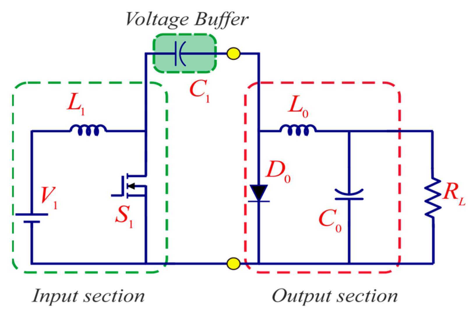
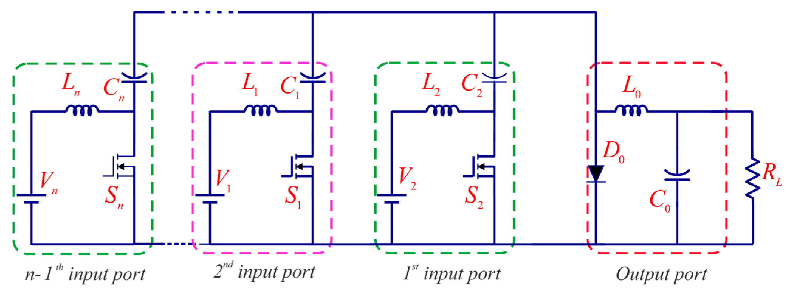
This section presents the illustration of synthesizing the proposed NI-TPC converter from a classical Cuk converter. Based on the fundamentals, the structure of the classical Cuk converter can be deduced to the input section, output section, and an energy buffer section that connects both, as shown in Figure 2. The capacitor acts as a voltage buffer and transfers energy from input to output section without consuming any energy. The input with voltage buffer and output sections are separated and connected as represented in Figure 2 to form the generalized n-port structure.
The resulting structure of the proposed ‘n’ port converter consists of ‘n-1’ input sources, ‘n’ inductors, ‘n’ capacitors, ‘n-1’ switches and a single diode is presented in Figure 3. Table 1 gives a comparison of the circuit elements used in the proposed and conventional structures.
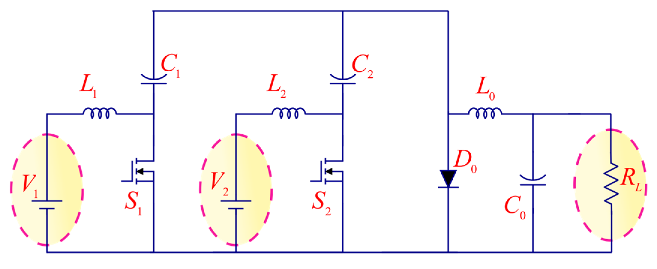
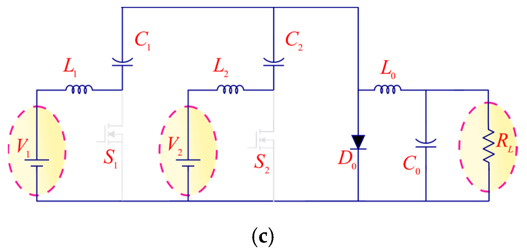
A three-port converter with two input ports and a load port is taken for better understanding as shown in Figure 4. One can understand that it is based on the integration of two classical Cuk converters. The proposed TPC consists of three inductors (L1, L2, and L0), three capacitors (C1, C2, and C0), two switches (S1–S2), and one diode (D0). Power sources V1 and V2 are connected to the unidirectional input ports.

2.2. Operating Principles

Based on the availability of power sources, the proposed TPC can function in two different modes: the SISO and dual input single output (DISO) modes. Either of the input ports can cater to load in the absence of the other in SISO mode. In DISO mode, both sources contribute power to load when the primary power source is insufficient to meet the load demand. The proposed NI-TPC converter can function in all these modes through appropriate control.

2.2.1. SISO Mode

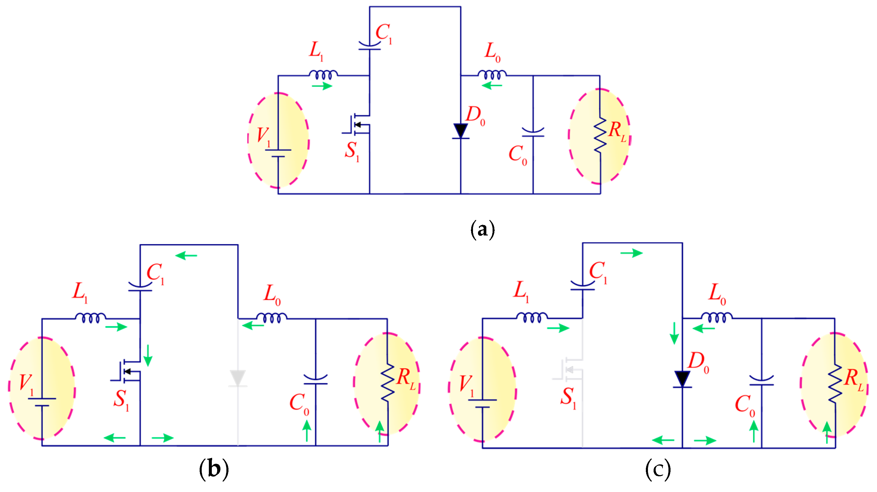
Figure 5a shows the Equivalent circuit when operating in SISO mode. The equivalent circuits of state 1 and state 2 are shown in Figure 5b,c, respectively. The waveforms are not shown since it is similar to the classical Cuk converter.

State 1

In this mode, switch S1 is ON, but the diode is not conducting. Voltage source V1 magnetizes the inductor L1. The positive voltage on the inductor makes the inductor current iL1 to increase linearly. The capacitor C1 is assumed precharged and discharging its energy to the load through the inductor L0. Hence, the inductor current iL2 increases linearly. In addition, it charges the output capacitor C0. Various currents and voltages can be expressed by (1).
V L 1 = V 1 , V L 0 = V C 1 V C 0 i C 1 = i L 0 i C 0 = i L 0 i 0 }

State 2

In this state, switch S1 is OFF while the diode conducts and freewheels. The voltage source V1 together with the energy stored in the inductor L1, charge the capacitor C1 through diode D0. The current in the inductor iL1 decreases linearly. The output inductor L0 is demagnetized and its energy flows to the load through diode D0. Equation (2) is valid in this mode:
V L 1 = V 1 V C 1 , V L 0 = V C 0 i C 1 = i L 1 i C 0 = i L 0 i 0 }
V 0 V 1 = D 1 1 D 1 I L 1 = P 1 V 1 , I L 0 = P 0 V 0 R L = V 0 2 P 0 }

2.2.2. DISO Mode

Better utilization of power sources needs a suitable control technique to achieve the regulated output power. The appropriate switching pattern in various modes depends on the time multiplexing of switching signals.
Selection of switching sequence can be done in many ways based on whether power is catered individually or simultaneously. A left-aligned switching pattern as shown in Figure 6 has been chosen in this work for analysis of the proposed converter.

State 1

During this state, both switches S1 and S2 are ON, but the diode remains nonconducting. The voltage sources V1 and V2 magnetize the inductors L1 and L2 respectively. The positive voltage on the inductors makes the inductor currents increase linearly. Capacitors C1 and C2 are assumed precharged and to be discharging energy. The load is catered by the capacitors discharge through the inductor L0. The corresponding equivalent circuit is illustrated in Figure 7a. The corresponding equations have been presented in (4).
V L 1 = V 1 , V L 2 = V 2 V L 0 = V 0 V C 1 i C 1 + i C 2 = i L 0 i C 0 = i L 0 i 0 }

State 2

In this interval, switch S1 is OFF and switch S2 is ON, but the diode stays nonconducting due to the voltage across capacitor C2. The voltage source V1 together with the energy stored in the inductor L1, charges the capacitor C1. V2 continues to discharge and magnetize the inductor L2. Due to the positive and constant voltage on inductor L2, its current raises linearly. The capacitor C2 continues to discharge as in Mode 1, and the load is catered by it through the inductor L0. The corresponding equivalent circuit is presented in Figure 7b. Equation (5) is derived for this mode.
V L 1 = V 1 V C 1 + V C 2 V L 2 = V 2 , V L 0 = V 0 V C 2 i C 1 = i L 1 , i C 2 = i L 0 i C 1 i C 0 = i L 0 i 0 }

State 3

In this state, both switches S1 and S2 are OFF while the diode conducts and freewheels. The voltage sources V1 and V2 together with the energy stored in the inductors L1 and L2, charge capacitors C1 and C2 respectively. The current in the inductors iL1 and iL2 decreases linearly. The output inductor L0 discharges and the load is catered by it through the Diode D0. The equivalent circuit of this state is illustrated in Figure 7c. Various currents and voltages can be expressed as in (6).
V L 1 = V 1 V C 1 V L 2 = V 2 V C 2 , V L 0 = V 0 i C 1 = i L 1 , i C 2 = i L 2 i C 0 = i L 0 i 0 }
Ideal operating conditions with Steady state and continuous conduction mode (CCM) is assumed to derive the expressions of the output voltage and voltage gain.

3. Modeling and Analysis of the Converter

The derivation of various parameters and modeling of the proposed NI-TPC converter are presented in this section.

3.1. Voltage Gain

The analytical expression for the output voltage has been obtained by applying volt second balance theory on inductors.
V 1 = V c 1 ( 1 δ 1 ) V c 2 ( δ 2 δ 1 )
V c 2 = V 2 ( 1 δ 2 )
V 0 = δ 1 V c 1 + δ 2 V c 2
The expression of the output voltage can be derived from Equations (7)–(9). The voltage equation in terms of duty cycles is
V 0 = δ 1 ( 1 δ 1 ) V 1 + δ 2 ( δ 2 δ 1 ) ( 1 δ 1 ) ( 1 δ 2 ) V 2 = G V 1 · V 1 + G V 2 · V 2
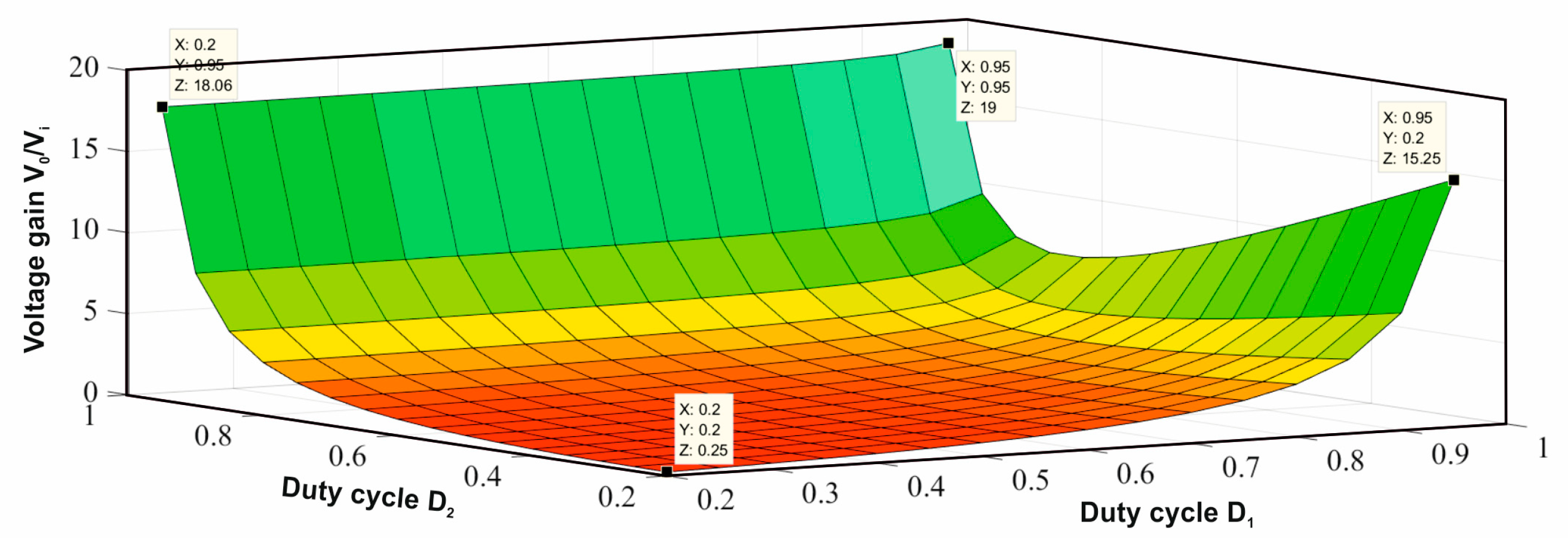
From (10), one can understand that the proposed converter operating in DISO mode has the same voltage gain compared with classical Cuk converter, which is plotted in Figure 8. Considering V1 = V2 = V, the output voltage of the proposed converter is presented in (11). Selecting the same duty ratio for both the switches leads to the output voltage equal to the one in classical Cuk converter as derived in (12). The voltage gain for an n-port DC–DC Cuk-Cuk converter with the proposed topology can be derived as in (13).
V 0 = δ 1 ( 1 δ 1 ) V 1 + δ 2 ( δ 2 δ 1 ) ( 1 δ 1 ) ( 1 δ 2 ) V 2 = G V 1 · V 1 + G V 2 · V 2
Taking δ1 = δ2 = δ
V 0 = δ 1 δ V
For an n-port converter,
V 0 = [ δ 1 1 δ 1 + i = 2 n δ i ( δ i δ 1 ) ( 1 δ 1 ) ( 1 δ i ) ] V i
Applying the charge-sec balance principle on capacitors, the following equations are obtained.
I C 1 = C 1 d V 1 d t = i L 0 d t δ 1 + i L 1 δ e + i L 1 δ o f f
i L 1 = δ 1 2 ( δ 1 1 ) i L 0
I C 2 = C 2 d V 2 d t = i L 0 2 δ 1 + ( i L 0 i L 1 ) δ e + i L 2 δ o f f
i L 2 = ( δ 1 δ 2 2 ( δ 1 1 ) δ 1 2 2 ( δ 1 1 ) δ 2 + δ 1 2 ) i L 0 ( 1 δ 2 )

3.2. Current Ripples of Inductors

Current ripples and inductor volt-second balance (IVSB) principle are used to design inductors. The inductor current ripple equations are modified to obtain equations for inductor values (16)–(18).
Δ i L 1 = V 1 δ 1 T S 2 L 1 = V 1 δ 1 2 L 1 f S L 1 = V 1 δ 1 2 Δ i L 1 f S }
Δ i L 2 = V 2 δ 2 T S 2 L 2 L 2 = V 2 δ 2 2 Δ i L 2 f S }
Δ i L 0 = δ 1 ( 1 δ 2 ) ( 1 δ 1 ) V 1 T S L 0 + δ 2 ( δ 2 δ 1 ) ( 1 δ 1 ) V 2 T S L 0 L 0 = δ 1 ( 1 δ 2 ) ( 1 δ 1 ) V 1 Δ i L 0 f S + δ 2 ( δ 2 δ 1 ) ( 1 δ 1 ) V 2 Δ i L 0 f S }
The values of the inductors can be found, if output voltage, source voltages, desired ripples, switching frequency and duty cycle are known.

3.3. Voltage Ripples of Capacitors

Voltage ripples and the capacitor charge-second balance (CCSB) principle are used to design capacitors. The voltage ripple equations are modified to obtain equations for capacitor values (19)–(21).
Δ V 1 = ( 1 δ 1 ) T S C 1 2 ( δ 1 1 ) δ 1 R   V 0 C 1 = ( 1 δ 1 ) Δ V 1 f S 2 ( δ 1 1 ) δ 1 R   V 0 }
Δ V 2 = ( 1 δ 2 ) T S R C 2 ( 1 δ 1 ) ( δ 1 δ 2 2 ( δ 1 1 ) δ 1 2 2 ( δ 1 1 ) δ 2 + δ 1 2 ) V 0 C 2 = ( 1 δ 2 ) R Δ V 2 f S ( 1 δ 1 ) ( δ 1 δ 2 2 ( δ 1 1 ) δ 1 2 2 ( δ 1 1 ) δ 2 + δ 1 2 ) V 0
Output capacitor can be determined from the output voltage ripple.
Δ V 0 = Δ i L 0 T S 8 C 0 C 0 = Δ i L 0 8 Δ V 0 f S
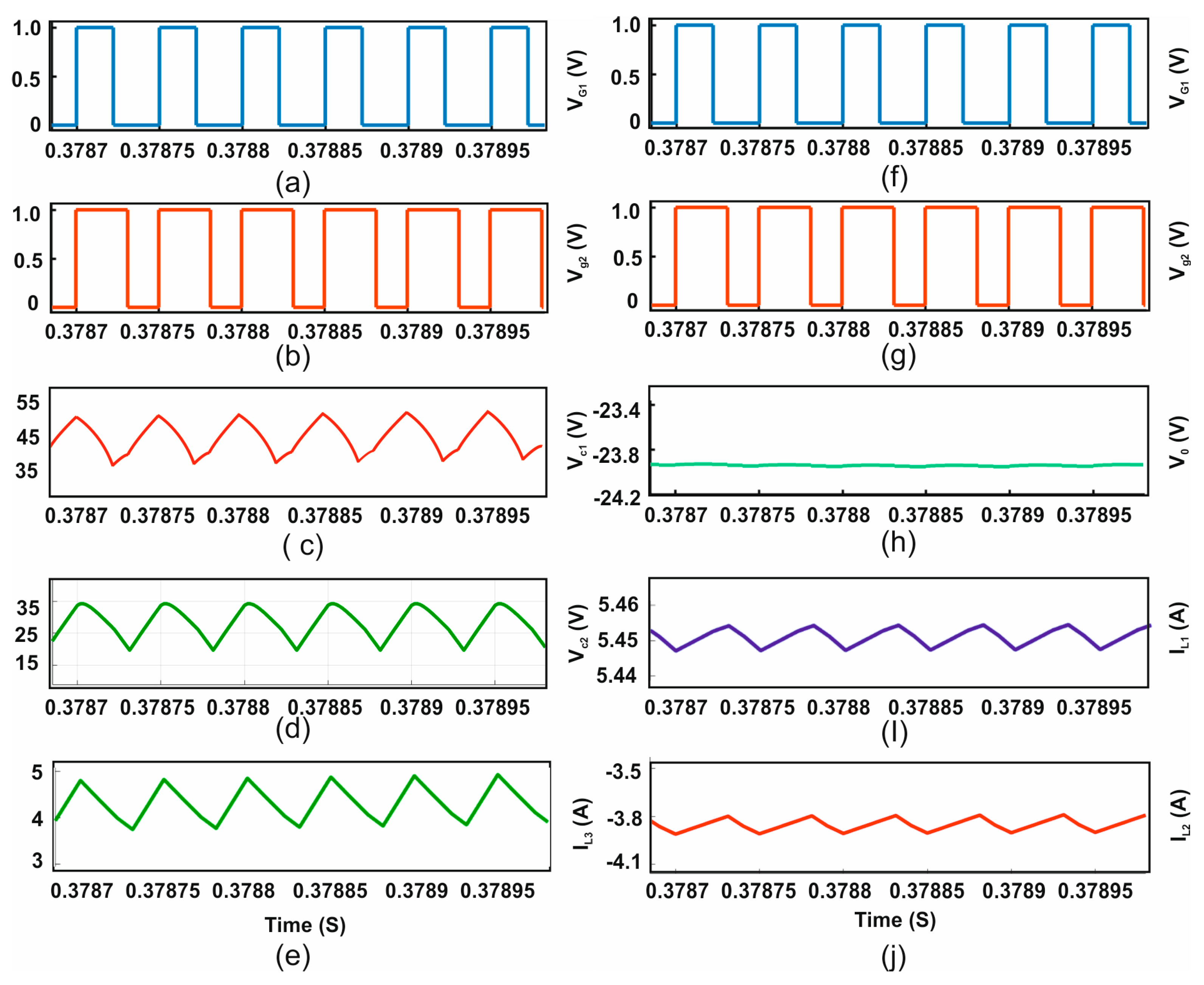
The values of the capacitors can be found if the output voltage, source voltages, desired ripples, switching frequency and duty cycle are known. A 5% current ripples in inductors, 5% voltage ripples in buffer capacitor C1 and 4% voltage ripples in output capacitor C0 have been considered to design the parameters listed in Table 2. The converter is simulated and various current and voltage waveforms are presented in Figure 9a–j.

3.4. Small-Signal Modeling

Voltage regulation should be maintained in spite of the changes in input and output parameters in any power converter, which necessitates a design of feedback controller. Modeling plays a good role in providing information about the dynamic behavior of the converter and in deriving a feedback control system. Numerous modeling methods have been proposed for power electronic converters. The State-Space Averaging (SSA) method is the most commonly used method to design control loops and to investigate the transient and steady state response of the converter. This modeling method has three steps: (1) writing the state-space equations for all states in a switching cycle; (2) derivation of average state-space equation; and (3) applying perturbations to the averaged equation to derive the linear first order small-signal equations, from which different transfer functions relating the inputs and outputs can be obtained. Then, matrices A and B are formed, which describe the converter model. The derived model fits in the following form (22).
X ˙ = A X + B U Y = C X + D U }
where X, U, Y and x ˙ = dx/dt represent the state vector, the input or control vector, the output vector and the derivative of X respectively. Matrices A, B, C and D are the system, control, output and feed-forward matrices respectively. A and B are used to extract various transfer functions of the system.
X = [ i L 1 i L 2 i L 3 v C 1 v C 2 v 0 ] T
U = [ V 1 V 2 ] T
Y = [ V 0 ]
From the Equation (4) in Section 2 and according to circuit theory, the dynamic equations representing state-1 can be written as follows
L 1 d i L 1 d t = V 1 , L 2 d i L 2 d t = V 2 L 0 d i L 0 d t = V 0 V C 1 C 1 d v C 1 d t + C 2 d v C 2 d t = i L 0 C 0 d v 0 d t = i L 0 i 0 }
The derived dynamic equations representing state-2 and state-3 are given in (27) and (28) respectively.
L 1 d i L 1 d t = V 1 V C 1 + V C 2 L 2 d i L 2 d t = V 2 , L 0 d i L 0 d t = V 0 V C 2 C 1 d v C 1 d t = i L 1 , C 2 d v C 2 d t = i L 0 i C 1 C 0 d v 0 d t = i L 0 i 0 }
L 1 d i L 1 d t = V 1 V C 1 L 2 d i L 2 d t = V 2 V C 2 , L 0 d i L 0 d t = V 0 C 1 d v C 1 d t = i L 1 , C 2 d v C 2 d t = i L 2 C 0 d v 0 d t = i L 0 i 0 }
The obtained state space model in matrix form is given in (29).
[ d i L 1 d t d i L 2 d t d i L 3 d t d v C 1 d t d v C 2 d t d v 0 d t ] = [ 0 0 0 δ 1 1 L 1 ( δ 2 δ 1 ) L 1 0 0 0 0 0 ( 1 δ 2 ) L 2 0 0 0 0 δ 1 L 0 ( δ 2 δ 1 ) L 0 1 L 0 1 δ 1 C 1 0 δ 1 2 C 1 0 0 0 ( δ 2 δ 1 ) C 2 1 δ 2 C 2 δ 2 δ 1 C 2 δ 1 2 C 2 0 0 0 0 0 1 C 0 0 0 1 R C 0 ] [ i L 1 i L 2 i L 0 v C 1 v C 2 v 0 ] + [ 1 L 1 0 0 1 L 2 0 0 0 0 0 0 0 0 ] [ V 1 V 2 ]
[ V 0 I 0 ] = [ 0 0 0 0 0 1 0 0 0 0 0 1 R ] [ i L 1 i L 2 i L 0 v C 1 V C 2 V 0 ] + [ 0 0 0 0 ] [ V 1 V 2 ]
Using (29) with the obtained model, the transfer functions are derived and shown in (30)–(32).
T = C [ S I A ] 1 B + D
V 0 V 1 = 8.889 × 10 10 s 2 9.877 × 10 19 s 6 + 41.67 s 5 + 9.406 × 10 7 s 4 + 3.919 × 10 9 s 3 + 2.092 × 10 15 s 2 + 8.711 × 10 16 s + 3.951 × 10 19
V 0 V 2 = 1.333 × 10 12 s 2 3.556 × 10 19 s 6 + 41.67 s 5 + 9.406 × 10 7 s 4 + 3.919 × 10 9 s 3 + 2.092 × 10 15 s 2 + 8.711 × 10 16 s + 3.951 × 10 19
These transfer functions are evaluated using MATLAB commands to eliminate manual mistakes, and the step data analysis is obtained. Figure 10 illustrates the response of the plant to a unit step input.
Figure 10a,b depicts the step response of the converter with step change in input sources V1 and V2 respectively. It is clear that the response is inverted as the Cuk converter has an inverted output. The steady state value settles at −0.6674 in Figure 10a and has an error of 33.26% with a peak overshoot of 62.7284%. In Figure 10b, the response settles at −0.9993 and has an error of 0.7% with a peak overshoot of 62.64644%.

4. Design of Controller

The most popular proportional plus integral (PI) controller has been designed to eliminate the steady state error pointed in Figure 10. One can obtain the proportional and the integral output as given in (30).
P o u t = K p e ( t ) , I o u t = K i 0 t e ( t ) d t
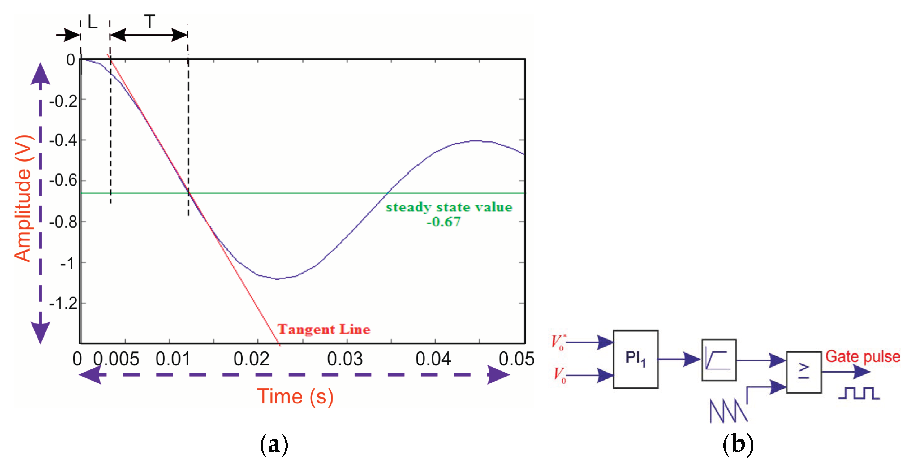
Ziegler–Nichols PI tuning was adopted to obtain the values of the proportional gain Kp and integral time Ti. The S-shaped waveform can be defined by two parameters, delay time L and time constant T as illustrated in Figure 11a.
The designed PI controller has been incorporated with the plant as shown in Figure 11b. The parameters of the controller can be obtained as given in (34)
P I c o n t r o l l e r = K p ( 1 + 1 T i S ) , K P = 0.9 T L , T i = L 0.3 }
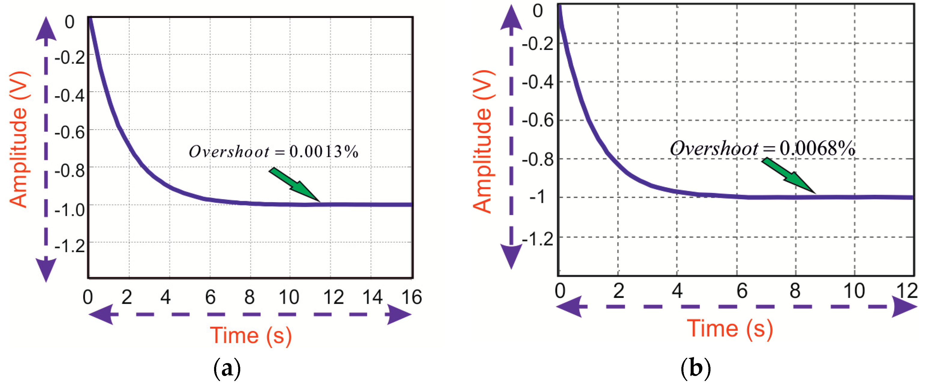
Figure 12a,b show the step response of the converter with PI controller for the step change in input sources V1 and V2 respectively. The steady state error is reduced and overshoots of 0.0013% and 0.0068% are achieved. To make both sources work effectively, with the magnitude of input voltage V1 > V2, the duty cycle is considered as δ1 < δ2.

5. Results and Discussion

A 100 W, 20 kHz NI-TPC converter using MOSFET switches was fabricated in the laboratory (Figure 13.) with the designed values. The whole system consists of the developed converter, two DC power sources representing the renewable energy sources such as PV and fuel cell, a FPGA spartan6 controller board, and a resistive load. Triggering signals for the switches and the controller are realized using FPGA Spartan 6 controller board. The specifications of components used are listed in Table 2.
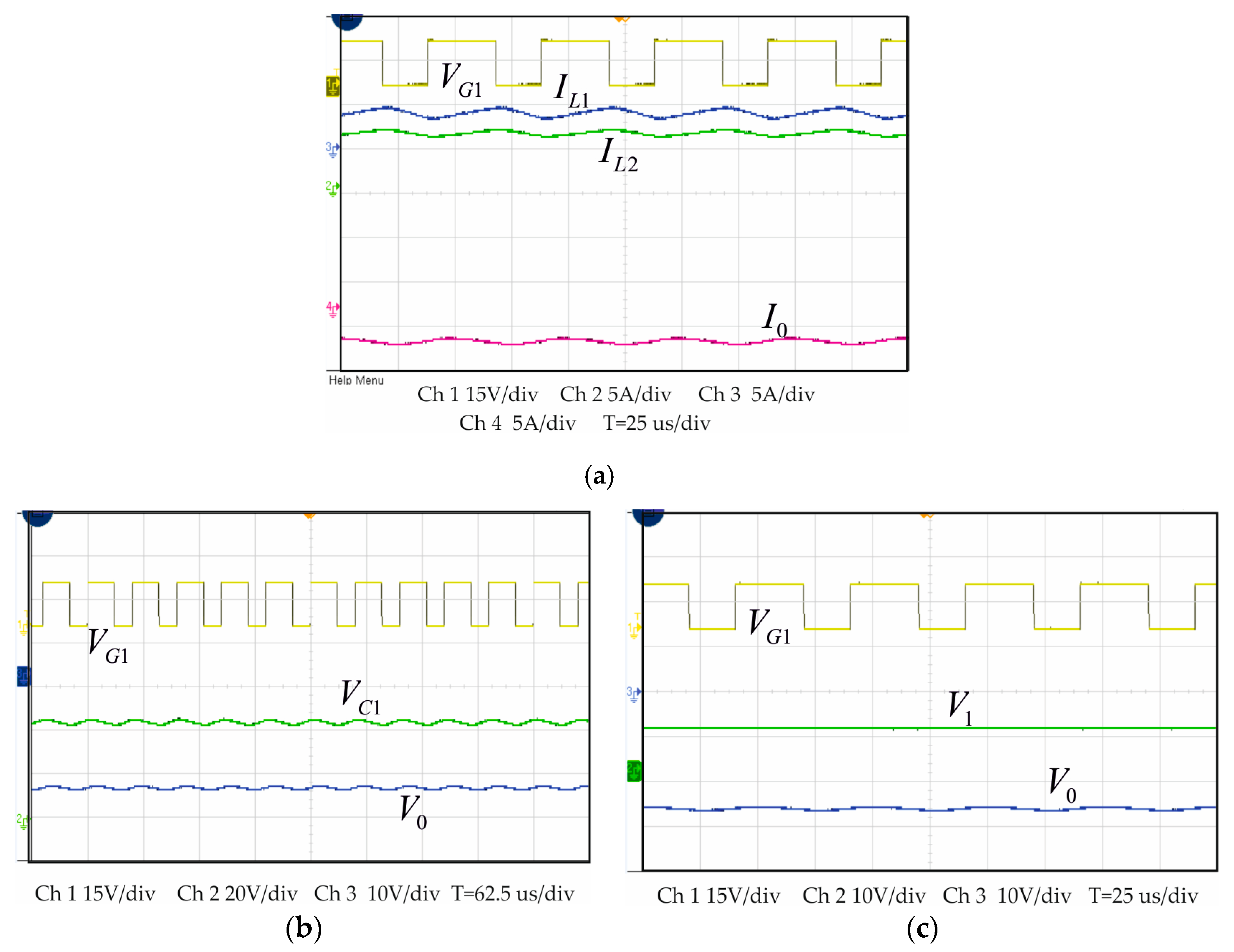
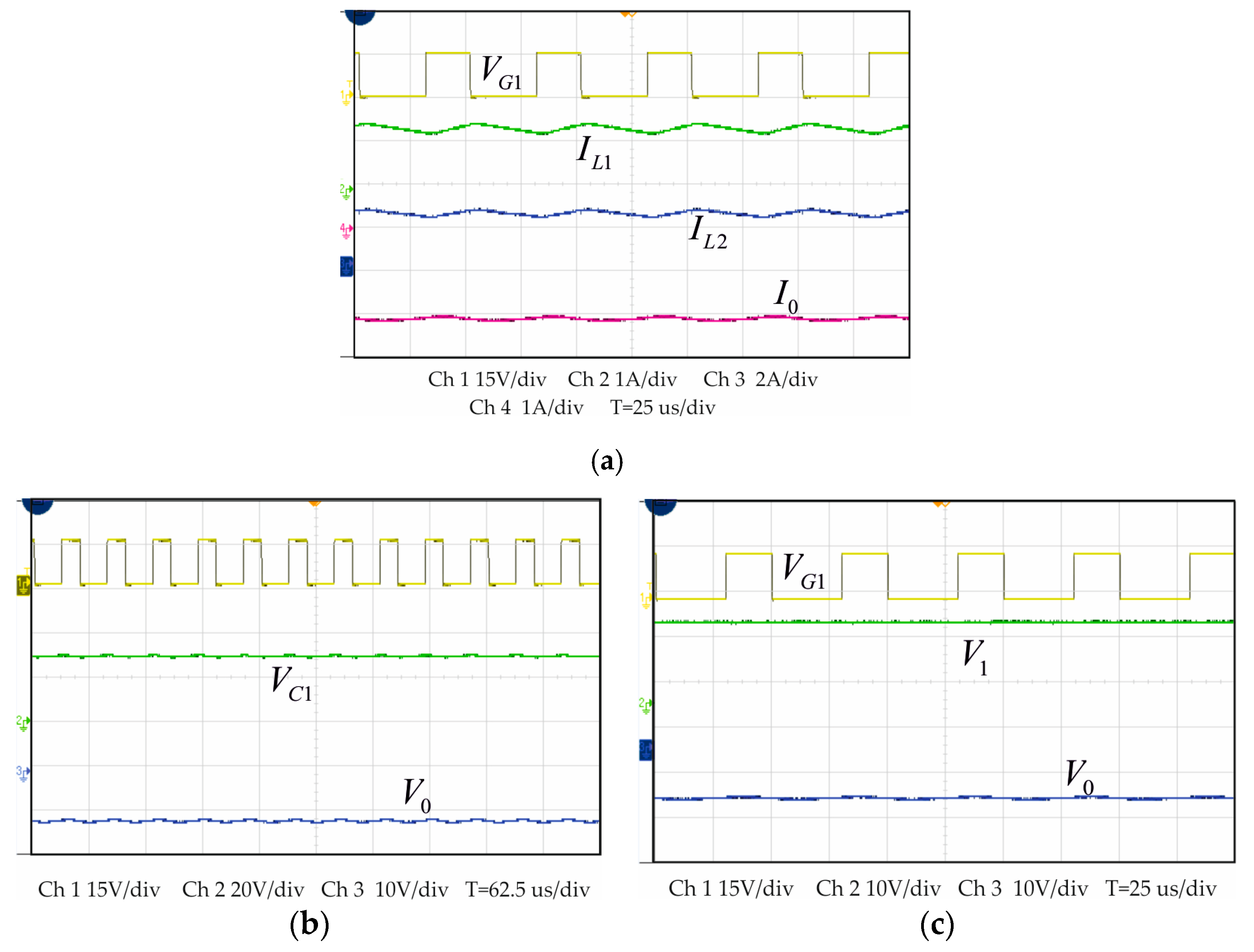
Experiments have been conducted using the proposed NI-TPC converter with an 18 V input voltage. Duty ratios of 60% and 40% were chosen for the boost and buck operations respectively. The results are shown in Figure 14 and Figure 15. Also, the test has been performed with 12 V input voltage and observed that the performance is satisfying the theoretical analysis. However, these results are not provided in this paper.
Figure 14a shows the current through inductors L1, L2 and the load current I0 along with gate signal applied under boost operation. It can be seen that the current ripples of inductors ΔiL1, ΔiL2 and load current Δi0 are in between (5.9 A, 5.3 A), (4.3 A, 3.4 A) and (4.2 A, 3.4 A) respectively. The average values and ripples are in close approximation with the 5.55 A, 3.71 A, and 3.6 A calculated from (2) and (3). The voltage across the capacitors C1 and C2 along with gate signal are shown in Figure 14b. From Figure 14b, the average voltages across the capacitors are 44 V and −26.2 V which are in agreement with the theoretical calculations from (1) and (2). The generated gate signal and source and output voltages are 15 V, 18 V, and −26.2 V, respectively, as shown in Figure 14c.
Figure 15a shows the current through the inductors L1, L2 and load current 1.4 A, 2.2 A and 2.17 A, under step down mode, which are closer to 1.39 A, 2.08 A, and 2.08 A calculated from (2) and (3). The corresponding ripples ΔiL1, ΔiL2 and Δi0 are within (1.55, 1.25 A), (2.4 and 2.0 A) and (2.3 and 2.1 A) respectively. It is found that the ripples are slightly more than the designed value of 5%. The voltage ripples of the capacitor are shown in Figure 15b. It can be seen that the ripples of capacitors are within (28.8, 29.55 V) for C1 and (11.0 to 11.4 V) for C2. The gate signal, source and output voltages are 15 V, 18 V and −11.2 V respectively, as shown in Figure 15c.
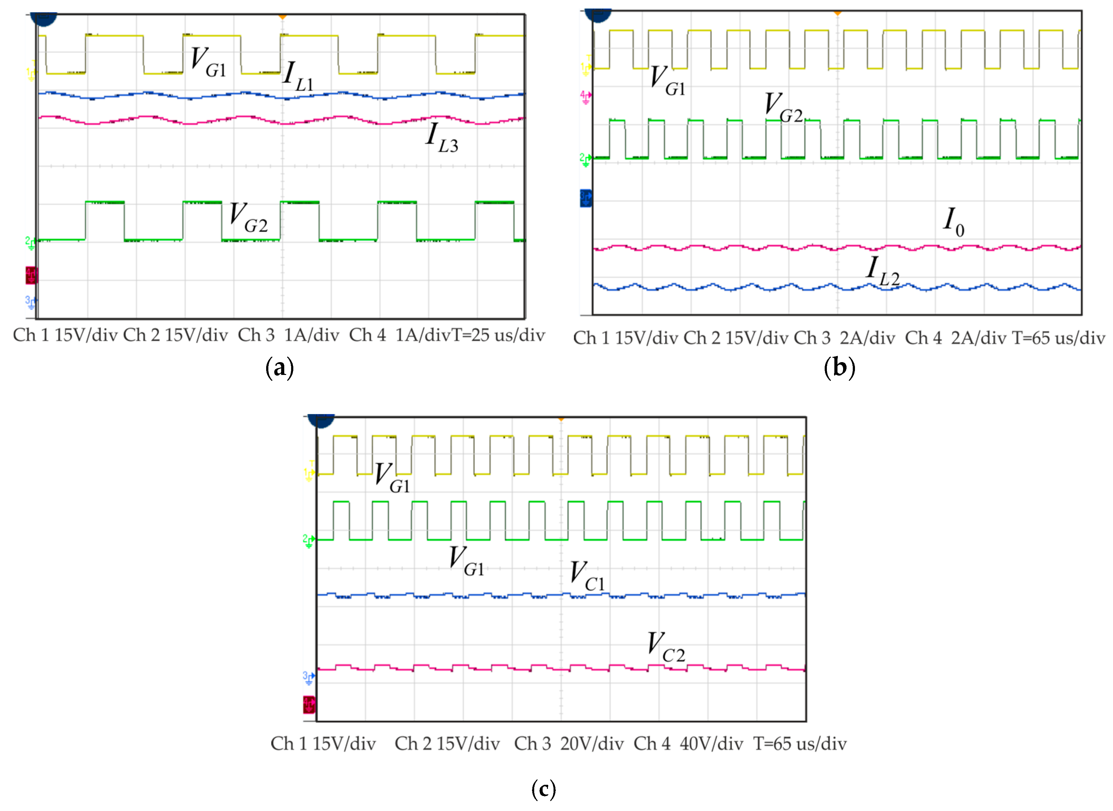
The performance of the converter was tested in DISO mode and the corresponding voltage and current signals are shown in Figure 16. The current through the inductors L1 and L3 with gate signal applied to both the switches are shown in Figure 16a. The inductor currents iL2 and i0 are shown in Figure 16b. It can be observed that the average inductor currents are matching with results from (3), (14) and (15) and ripples are slightly more than the designed value of 5%. The voltage across the capacitors C1 and C2 are 40 V and 34 V respectively as shown in Figure 16c. It can be seen that the ripples of capacitors are within (36.5 V, 44.5 V) for C1 and (31.5 to 39 V) for C2. The obtained voltage ripples (approximately 10%) are more than the designed value (5%). However, it can be observed that the current of all the ports, IL1, IL2 and I0 are continuous with less ripples.
The response of the converter during transient load condition is shown in Figure 17. The load is varied to increase the load current from 0.6 A to 3.8 A. Approximately 20 s later, the load decreased to 0.8 A from 3.8 A. In both the cases, it is observed that the load voltage is regulated at 23.9 V which is closer to the desired value of 24 V. The load voltage magnitude is shown positive by using the probe with opposite polarity.
Figure 18a,b present the comparison plot between the theoretical, simulation and experimental absolute values of voltage gains as a function of duty ratio for SISO and DISO modes, respectively. It is obvious that both the theoretical and experimental voltage gains are increasing as the duty ratio increases. In addition, the voltage gain obtained from the experiment closely approximates the theoretical and the simulation results between 0.3 and 0.5, whereas a slight deviation has been observed in the duty ratio beyond 0.5 with increasing voltage difference. It is worth mentioning that this difference is due to the component losses.
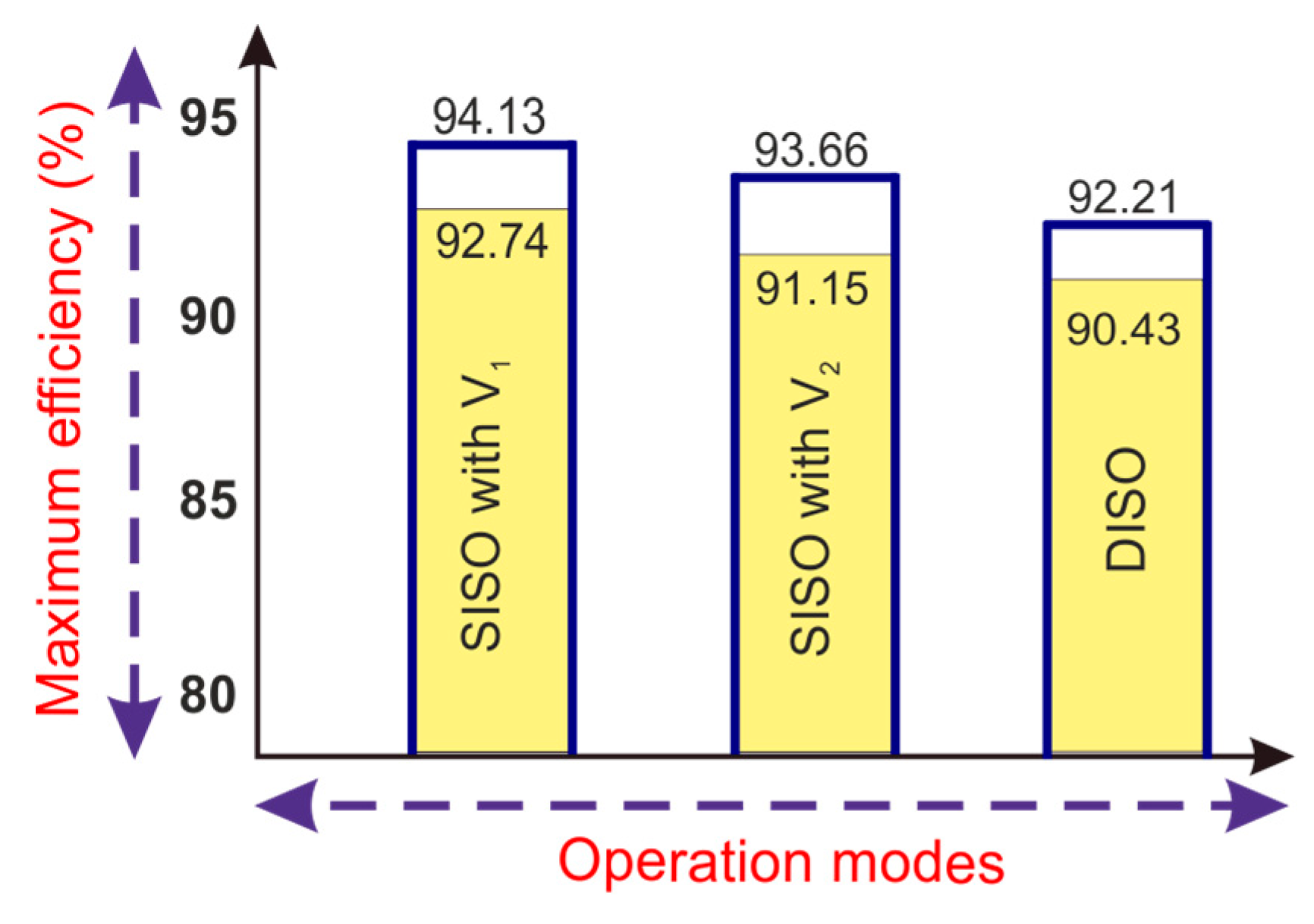
Thus, the results validate the theoretical analysis and show the good feasibility of expected operation. Several tests are conducted and the maximum efficiency between the modes has been compared and plotted in a graph as shown in Figure 19, and the observed efficiencies for Mode 1 (SISO) with V1 and V2 sources are 92.74% and 91.15% respectively, and for Mode 2 is 90.43%. Comparing with efficiencies obtained through simulation, efficiencies for Mode 1 (SISO) with individual contribution of V1 and V2 sources are 94.13% and 93.66%, respectively, and for Mode 2 is 92.21%. Table 3 presents the comparison of various TP-NI converters with the proposed one. It is clear that the proposed converter provides continuous current at all the ports with a reduction in components.

6. Conclusions

In this paper a NI-TPC converter is synthesized using conventional Cuk converters to interface RS like Fuel cell and PV source. The operational modes and analysis of the converter are discussed in detail. Fewer active and passive components and a shared output inductor are the advantages of this converter. The continuous input and output currents are achieved owing to the presence of inductors. Therefore, this converter is appropriate for FC power supplies that necessitates continuous current with low ripple. The simulation and experimental results are provided to verify the feasibility of the proposed converter.

Author Contributions

Formal Analysis, B.C.; Investigation, B.C.; Methodology, B.C.; Resources, C.N.; Supervision, C.N.; Validation, C.N.; Writing—Original Draft, B.C.; Writing—Review & Editing, B.C., C.N., and S.S.D.

Funding

This research received no external funding.

Acknowledgments

The authors would like to thank SRM IST, Kattankulathur, India for the financial support in executing this work successfully. This work has been carried out as a part of research work in the Department of Electrical and Electronics Engineering, SRM IST, Kattankulathur, India.

Conflicts of Interest

The authors declare no conflicts of interest.

References

  1. Wang, J.; Dunford, W.G.; Mauch, K. Synthesis of two-inductor DC-DC converters. In Proceedings of the Power Electronics Specialists Conference, Saint Louis, MO, USA, 27 June 1997; pp. 1367–1373. [Google Scholar]
  2. Landsman, E.E. A unifying derivation of switching DC-DC converter topologies. In Proceedings of the IEEE Power Plectronics Ppecialists Ponference, San Diego, CA, USA, 18–22 June 1979; pp. 18–22. [Google Scholar]
  3. Khaligh, A.; Cao, J.; Lee, Y.-J. A multiple-input DC–DC converter topology. IEEE Trans. Power Electron. 2009, 24, 862–868. [Google Scholar] [CrossRef]
  4. Kumar, L.; Jain, S. Multiple-input DC/DC converter topology for hybrid energy system. IET Power Electron. 2013, 6, 1483–1501. [Google Scholar] [CrossRef]
  5. Zhou, Z.; Wu, H.; Ma, X.; Xing, Y. A non-isolated three-port converter for stand-alone renewable power system. In Proceedings of the IECON 2012-38th Annual Conference on IEEE Industrial Electronics Society, Montreal, QC, Canada, 25–28 October 2012; pp. 3352–3357. [Google Scholar]
  6. Wang, C.-S.; Li, W.; Wang, Y.-F.; Han, F.-Q.; Meng, Z.; Li, G.-D. An isolated three-port bidirectional DC-DC converter with enlarged ZVS region for HESS applications in DC microgrids. Energies 2017, 10, 446. [Google Scholar] [CrossRef]
  7. Reddi, N.K.; Ramteke, M.R.; Suryawanshi, H.M. Dual-Input Single-Output Isolated Resonant Converter with Zero Voltage Switching. Electronics 2018, 7, 96. [Google Scholar] [CrossRef]
  8. Wu, Y.-E.; Chiu, P.-N. A High-Efficiency Isolated-Type Three-Port Bidirectional DC/DC Converter for Photovoltaic Systems. Energies 2017, 10, 434. [Google Scholar] [CrossRef]
  9. De Morais, J.L.S.; Gules, R. Three-port converter based on the bidirectional Ćuk and the LC series-resonant half-bridge topologies for renewable energy applications. In Proceedings of the Industry Applications (INDUSCON), Curitiba, Brazil, 20–23 November 2016; pp. 1–8. [Google Scholar]
  10. Zhu, H.; Zhang, D.; Zhang, B.; Zhou, Z. A nonisolated three-port dc–dc converter and three-domain control method for PV-battery power systems. IEEE Trans. Ind. Electron. 2015, 62, 4937–4947. [Google Scholar] [CrossRef]
  11. Georgious, R.; Garcia, J.; Garcia, P.; Navarro-Rodriguez, A. A Comparison of Non-Isolated High-Gain Three-Port Converters for Hybrid Energy Storage Systems. Energies 2018, 11, 658. [Google Scholar] [CrossRef]
  12. Fong, Y.; Cheng, K.; Raman, S.R.; Wang, X. Multi-Port Zero-Current Switching Switched-Capacitor Converters for Battery Management Applications. Energies 2018, 11, 1934. [Google Scholar] [CrossRef]
  13. Chen, Y.-M.; Liu, Y.-C.; Wu, F.-Y. Multi-input DC/DC converter based on the multiwinding transformer for renewable energy applications. IEEE Trans. Ind. Electron. 2002, 38, 1096–1104. [Google Scholar]
  14. Kwasinski, A. Identification of feasible topologies for multiple-input DC–DC converters. IEEE Trans. Ind. Electron. 2009, 24, 856–861. [Google Scholar] [CrossRef]
  15. Liu, Y.C.; Chen, Y.-M. A systematic approach to synthesizing multi-input DC–DC converters. IEEE Trans. Ind. Electron. 2009, 24, 116–127. [Google Scholar]
  16. Wu, H.; Xing, Y.; Xia, Y.; Sun, K. A family of non-isolated three-port converters for stand-alone renewable power system. In Proceedings of the IECON 2011-37th Annual Conference on IEEE Industrial Electronics Society, Melbourne, Australia, 7–10 November 2011; pp. 1030–1035. [Google Scholar]
  17. Wu, H.; Zhang, J.; Xing, Y. A family of multiport buck–boost converters based on DC-link-inductors (DLIs). IEEE Trans. Ind. Electron. 2015, 30, 735–746. [Google Scholar]
  18. Cheng, T.; Lu, D.D.-C.; Qin, L. Non-Isolated Single-Inductor DC/DC Converter with Fully Reconfigurable Structure for Renewable Energy Applications. IEEE Trans. Circuits Syst. Express Briefs 2018, 65, 351–355. [Google Scholar] [CrossRef]
  19. Zhao, J.; Iu, H.H.C.; Fernando, T.; An, L.; Lu, D.D.-C. Design of a non-isolated single-switch three-port DC-DC converter for standalone PV-battery power system. In Proceedings of the 2015 IEEE International Symposium on Circuits and Systems (ISCAS), Lisbon, Portugal, 24–27 May 2015; pp. 2493–2496. [Google Scholar]
  20. Cuk, S. A new zero-ripple switching DC-to-DC converter and integrated magnetics. IEEE Trans. Magn. 1983, 19, 57–75. [Google Scholar] [CrossRef] [Green Version]
  21. Almalaq, Y.; Matin, M. Three topologies of a non-isolated high gain switched-inductor switched-capacitor step-up cuk converter for renewable energy applications. Electronics 2018, 7, 94. [Google Scholar] [CrossRef]
  22. Kumar, M.; Babu, Y.N.; Pullaguram, D.; Mishra, S. A high voltage gain non-isolated modified three-port DC/DC converter based on integrated Boost-Cuk topology. In Proceedings of the Asia-Pacific Power and Energy Engineering Conference (APPEEC), Bangalore, India, 8–10 November 2017; pp. 1–6. [Google Scholar]
  23. Biswas, S.; Dhople, S.; Mohan, N. A three-port bidirectional dc-dc converter with zero-ripple terminal currents for pv/microgrid applications. In Proceedings of the IECON 2013-39th Annual Conference of the IEEE Industrial Electronics Society, Vienna, Austria, 10–13 November 2013; pp. 340–345. [Google Scholar]
  24. Biswas, S.; Dhople, S.; Mohan, N. Zero-ripple analysis methods for three-port bidirectional integrated magnetic Ćuk converters. In Proceedings of the IECON 2014-40th Annual Conference of the IEEE Industrial Electronics Society, Dallas, TX, USA, 29 October–1 November 2014; pp. 1889–1895. [Google Scholar]
  25. Ferrera, M.B.; Litran, S.P.; Aranda, E.D.; Marquez, J.M.A. A converter for bipolar DC link based on SEPIC-Cuk combination. IEEE Trans. Power Electron. 2015, 30, 6483–6487. [Google Scholar] [CrossRef]
  26. Chen, Y.; Zhang, P.; Zou, X.; Kang, Y. Dynamical modeling of the non-isolated single-inductor three-port converter. In Proceedings of the Applied Power Electronics Conference and Exposition (APEC), Fort Worth, TX, USA, 16–20 March 2014; pp. 2067–2073. [Google Scholar]
  27. Sato, Y.; Nagata, H.; Uno, M. Non-isolated multi-port converter integrating PWM and phase-shift converters. In Proceedings of the Region. 10 Conference, Penang, Malaysia, 5–8 November 2017; pp. 1097–1102. [Google Scholar]
  28. Yang, H.; Chao, K.; Sun, X.; An, S.; Ren, B.; Zhang, Q. Analysis, modeling and control of a non-isolated four-port dc-dc converter for independent photovoltaic power generation system. In Proceedings of the IECON 2017-43rd Annual Conference of the IEEE Industrial Electronics Society, Beijing, China, 29 October –1 November 2017; pp. 7731–7735. [Google Scholar]
  29. Balaji, C.; Dash, S.S.; Hari, N.; Babu, P.C. A four port non-isolated multi input single output DC-DC converter fed induction motor. In Proceedings of the 2017 IEEE 6th International Conference on Renewable Energy Research and Applications (ICRERA), San Diego, CA, USA, 5–8 November 2017; pp. 631–637. [Google Scholar]
  30. Akar, F.; Tavlasoglu, Y.; Ugur, E.; Vural, B.; Aksoy, I. A bidirectional nonisolated multi-input DC–DC converter for hybrid energy storage systems in electric vehicles. IEEE Trans. Veh. Technol. 2016, 65, 7944–7955. [Google Scholar] [CrossRef]
  31. Chen, Y.-M.; Huang, A.Q.; Yu, X. A high step-up three-port DC–DC converter for stand-alone PV/battery power systems. IEEE Trans. Power Electron. 2013, 28, 5049–5062. [Google Scholar] [CrossRef]
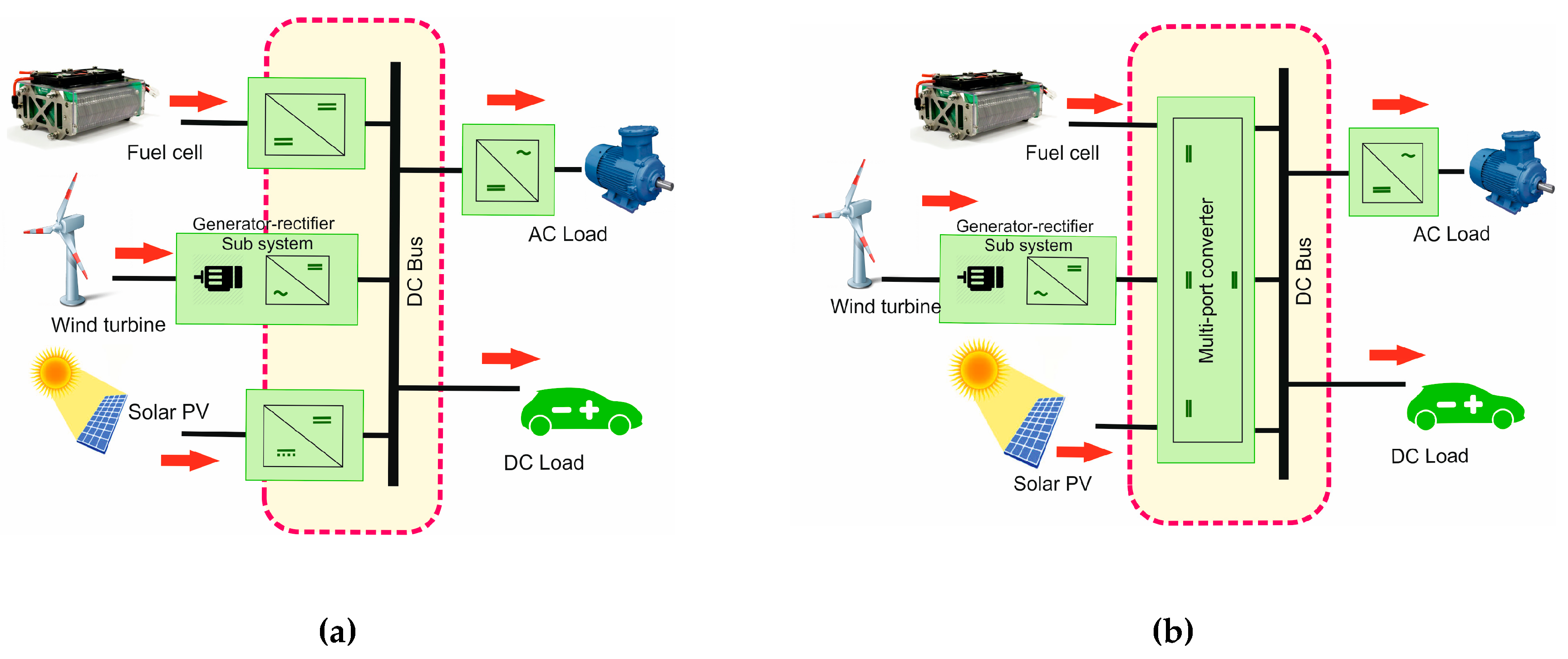
Figure 1. (a) Structure of the conventional system, (b) Proposed multiport converter (MPC) system.
Electronics 08 00214 g001
Figure 2. Structure of classical Cuk converter.
Electronics 08 00214 g002
Figure 3. Generalized structure of the proposed ‘n’ port converter.
Electronics 08 00214 g003
Figure 4. Proposed three-port converter.
Electronics 08 00214 g004
Figure 5. (a) Single input–single output (SISO) mode of the proposed converter: (b) State 1 and (c) State 2.
Electronics 08 00214 g005
Figure 6. Left-aligned switching pattern.
Electronics 08 00214 g006
Figure 7. Equivalent circuits: (a) State 1, (b) State 2, and (c) State 3.
Electronics 08 00214 g007aElectronics 08 00214 g007b
Figure 8. Voltage gain Vs Duty cycle of NI-TPC converter.
Electronics 08 00214 g008
Figure 9. Waveforms of various voltages and currents during mode 2 (a,f) Gate signal to S1, (b,g) Gate signal to S2, (c) Voltage across capacitor C1, (d) Voltage across capacitor C2, (e) Current through the inductor i3, (h) Output voltage (i) Current through the inductor L1, (j) Current through the inductor L2.
Electronics 08 00214 g009
Figure 10. Step response of open loop system (a) with V1 source and (b) with V2 source.
Electronics 08 00214 g010
Figure 11. (a) S shaped curve. (b) Control with PI controller.
Electronics 08 00214 g011
Figure 12. Step response of the system in closed loop (a) with V1 source and (b) with V2 source.
Electronics 08 00214 g012
Figure 13. Hardware setup.
Electronics 08 00214 g013
Figure 14. Various voltage and current measurements from experiments during Mode 1 with source 1 (Boost mode): (a) Gate signal, inductor currents through L1, L2 and Load current (CH 1–4); (b) Gate signal and capacitor voltages across C1 and C2 (CH 1–3); (c) Gate signal, source voltages and output voltage (CH 1–3).
Electronics 08 00214 g014
Figure 15. Various voltage and current measurements from experiments during Mode 1 with source 1 (Buck mode): (a) Gate signal, inductor currents through L1, L2 and load current (CH 1–4); (b) Gate signal and capacitor voltages across C1 and C2 (CH 1–3); (c) Gate signal, source voltages and output voltage (CH 1–3).
Electronics 08 00214 g015
Figure 16. Various voltage and current measurements from experiments during Mode 2 with both sources: (a) Gate pulses of both switches and inductor currents through L1 and L3 (CH 1–4); (b) Gate pulses of switches, inductor currents through L2 and L0 (CH 1–4); (c) Gate signals of S1 and S2, and capacitor voltages across C1 and C2 (CH 1–4).
Electronics 08 00214 g016
Figure 17. Voltages and currents from the experiment during transient condition. Input voltage, input current, load voltage and current (CH 1–4).
Electronics 08 00214 g017
Figure 18. Voltage gain as a function of duty cycle (a) SISO mode (b) DISO mode.
Electronics 08 00214 g018
Figure 19. Maximum efficiency for various modes.
Electronics 08 00214 g019
Table 1. Comparison of circuit elements.
Circuit ElementsProposed n-Port Cuk-Cuk Converter(n-1) Individual Cuk Converters
Inductorsn2(n-1)
Capacitorsn2(n-1)
Switchn-1n
Diode12(n-1)
Table 2. Components of the proposed converter.
Sl.NoComponentSymbolSimulationHardware
1InductorsL1 and L20.8 & 1.51 mH1 & 1.5 mH
2CapacitorsC1 and C246.3 μF & 63 μF50 μF, 63 V & 72 μF, 50 V
3Output InductorL02 mH2 mH
4Output CapacitorC01.7 μF2.2 μF, 35 V
5Load ResistanceR5.76 Ω6 Ω
6Switching Frequencyfsw20 kHz20 kHz
Table 3. Comparison of converters.
Circuit Elements[5][10][22][30][31]The Proposed Converter
TopologyNonisolatedNonisolatedNonisolatedNonisolatedNonisolatedNonisolated
Inductors23222 coupled3
Capacitors343133
Active switches433452
Diodes2142Nil1
Common groundYesYesYesYesYesYes
Continuous current at all the portsNoYesNoNoNoYes
Prototype rating400 W1.2 kW200 W1 kW200 W100 W
Switching frequency100 kHz100 kHz40 kHz20 kHz50 kHz20 kHz
Maximum efficiency96%93.5%92.7%95.5%90.1%94.13%