1. Introduction
With the continued improvement of photovoltaics, photovoltaic power generation technology has been transformed from initial small-capacity distributed access to the development and utilization of large-scale centralized photovoltaic power plants [
1]. The access of large-scale photovoltaic power plants to the grid has profoundly changed the fault characteristics of traditional power grids. For example, when the negative sequence current is suppressed as the control target of the grid-connected inverter, there is no negative sequence current in the fault current of the photovoltaic power station side. A lesser concern is that this suppression of negative sequence current will cause the phase selection components of the line protection to be affected, which may cause risks, such as protection phase selection errors, and thus affect important functions, such as reclosing and protection ranging [
2].
At present, there is much literature on the effects of inverter-type new energy access to the grid on distance protection, reclosing, and differential protection [
3,
4,
5,
6,
7,
8]. The authors in [
3] analyze the current differential protection action performance of new energy power station transmission lines under different grid-connected systems, and finally obtain the following conclusions: Current differential protection may occur in weak systems under weak faults, but in strong systems the lower current differential protection sensitivity will decrease. Reference [
4] primarily studies the influence of grid-connected photovoltaics on distance protection and reclosing, and presents a new protection scheme. For the case of inverter-type new energy power supply represented by permanent magnet fan and photovoltaic, the short-circuit current provided by T-connected inverter power supply is regarded as unbalanced current in the literature [
5,
6], focusing on different capacity inverses. The article shows the effect of the modified power supply on the current differential protection performance of the transmission line, but the article applies the inverter type power supply to the ideal controlled current source, which does not reflect the true short-circuit current characteristics of the inverter power supply. In fact, with the increase in the proportion of inverter-type new energy access, only by combining the short-circuit current characteristics of the inverter type power supply and analyzing the differential and braking currents on both sides of the line can more accurately analyze the line differential protection performance [
7,
8]. The short-circuit current of the inverter type power supply is expressed by the function of the grid-connected point voltage, and the numerical calculation method of the short-circuit current of the inverter type power supply is given, but it is difficult to derive the fault line phase relationship of the side current based on the current value solution. In [
9,
10], based on different fault crossing control strategies, the analytical expression of a short-circuit current of inverter type power supply is derived, but the phase relationship between short-circuit currents of each phase of inverter power supply is not further analyzed, and the current is short-circuited with the system side. The phase relationship between the currents. However, the key to analyzing the differential protection performance is to solve the short-circuit current on both sides of the fault line and determine the relative phase relationship between the two sides of the current. In the conventional AC system, the phase relationship between the short-circuit currents, on both sides of the line after the fault, is determined according to the constant potential of the synchronous generator, before and after the fault on both sides of the line. This assumption is not true for the new energy source, so, in the new energy power access scenario, how to solve the fault current of a new energy source and determining the phase relationship of the fault current on both sides of the line are difficult points to analyze in order to ascertain the performance of differential protection. Reference [
11] studies the influence of collection line protection on the photovoltaic power station, and proposes a new protection method for the distance protection of the collection line. The authors of [
5,
6] analyze the impact of renewable energy on distance protection. In [
12], based on the characteristics of transient current waveforms of synchronous generators and various new energy sources, a new principle of longitudinal protection, based on waveform correlation, is proposed. The authors of [
13] analyzed the mechanism of influence of inverter-type new energy on the current and phase components of the fault. However, none of the above literature analyzes the impact of new energy access on the protection of phase selection components.
The phase selection component is used as the fault phase identification component for the power system’s automatic reclosing, protection ranging, and distance protection. The correct phase selection determines the action performance of reclosing, protection ranging, and distance protection. The authors of [
14] studied the influence of the phase difference component of the phase difference of the phased current component of the photovoltaic power station, and built a corresponding phase selection component model for testing, but did not model its impact on the line. The fault current characteristics and the mechanism that influences the Photovoltaic (PV) power plant access on the phase selection components were analyzed in depth. In [
15], under the condition of an AC power failure of an inverter-type power supply, the influence of the positive sequence component control strategy on the phase selection components is studied from the perspective of the fault sequence impedance characteristics. It is concluded that the inverter power supply side cannot be correctly phased and that the system side can be correctly phased. The conclusions of the phase selection process are not theoretically analyzed for the adaptability of the phase selection components under different control objectives, and the mathematical analytical formulas of the fault currents at the transmission lines, under the three control targets, are not given.
In this paper, an analytical expression of the fault current on the side of the photovoltaic power station and its impact on the transmission line are directly derived. Under the three different control strategies of suppressing the negative sequence current, suppressing the active fluctuation, and suppressing the reactive power fluctuation, the relationship between the amplitude and phase of the phase current difference is derived. The fault current sequence phase current difference is further derived.
Then we calculate the phase relationship between quantities, and then analyze the control target, active and reactive reference commands, fault type, positive sequence voltage drop depth, and degree of grid voltage imbalance present in the two voltage relationships. Finally, this study presents appropriate fault-traversing strategies. The relationship between various factors demonstrates that the performance of the phase selection component of the photovoltaic power station on regulating the current of the outgoing line is affected by the fault traversal strategy of the inverter and the fault condition, and that there is a possibility of incorrect operation. Finally, a model is built in Power System Computer Aided Design/ Electromagnetic Transient Design and Control (PSCAD/EMTDC) to simulate the successful performance of the phase selection components under various types of faults.
2. Methodology
The analytical expression of the fault current on the side of the photovoltaic power station was directly derived, as well as its impact on the transmission line. Under the three different control strategies of suppressing the negative sequence current, suppressing the active fluctuation, and suppressing the reactive power fluctuation, the relationship between the amplitude and the fault current sequence phase current difference was derived. The phase relationship between current quantities was derived, followed by an analysis of the control target , active and reactive reference commands, fault type, positive sequence voltage drop depth, and the grid voltage imbalance used in the two voltage relationships, and finally the fault traversal strategies. The relationship between the various factors demonstrated that the action performance of the phase selection component of the photovoltaic power station on the outgoing line was affected by the fault traversal strategy of the inverter and the fault condition, and that there was a possibility of incorrect operation. Finally, a model was built in PSCAD/EMTDC to simulate the performance of the phase selection components under various types of faults.
3. Analysis of Fault Current Characteristics
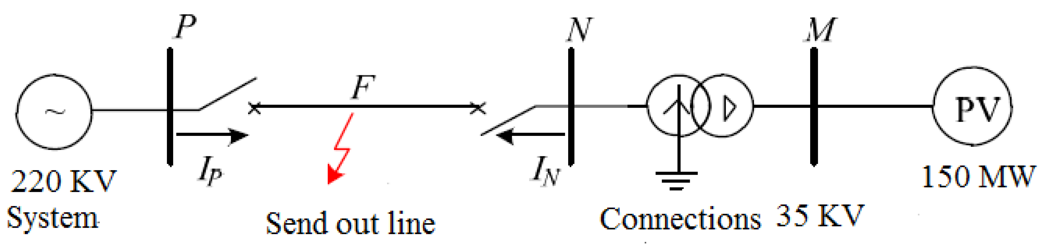
This article proposes a large-scale solar power system with a rated capacity of 150 MW in a certain area. The power station was the research object, and its grid-connected model is shown in
Figure 1.
When the asymmetric point occurs at the midpoint of the transmission line of the photovoltaic power station, the mathematical analysis of the reference value of the fault current of the photovoltaic power station, based on each control target, is expressed by [
15]:
where
respectively represent the voltage and current quantities of the PV power plant, with subscripts
,
and
,
representing the positive and negative sequence components in the
coordinate system, respectively, and the superscript
is the reference value. The parameter
is the measured value, having values of 0, 1, −1, which, respectively, correspond to the suppression of negative sequence current, and suppression of active and reactive power fluctuations of the control target;
and
are the reference values of the active and reactive power of the PV unit during a fault;
,
.
When the classic dual vector control strategy was adopted, the response speed was generally within 10 ms. It can be considered that the grid-connected inverter quickly entered the steady state, and the actual value of the fault current was basically equal to the current reference value. Since the low-voltage side of the main transformer of the PV power plant adopted
-type wiring, the zero-sequence current had no path, so the 35 KV side current only contained positive and negative sequence components, and the three-phase instantaneous fault current of the inverter output can be expressed as:
where
,
,
is the fundamental angular frequency;
,
,
, and
is the magnitude of the positive sequence current vector at fault. Furthermore,
where
is the magnitude of the negative sequence current vector at the fault,
is the rated voltage amplitude of the grid,
is the positive sequence voltage drop coefficient of the grid connection point of the inverter,
is the grid voltage imbalance, and
and
are the magnitudes of the positive sequence and negative sequence voltage vectors, respectively.
From Equations (2) and (3), when the asymmetrical fault occurs in the transmission line (Phase-Neutral (PN) segment), then the fault current of the photovoltaic side (Neutral (N)-side) is analytically expressed as:
where,
Here,
is the main transformer ratio;
,
, and
respectively, represent the inverter output current amplitude, gain coefficient, and initial phase angle; and
and
are the zero-sequence current amplitude and the initial phase angle on the outgoing line, respectively.
According to the analysis in this section, the fault current characteristics of the PV power supply line could be obtained as follows:
(1) The fault current on the side of the PV power station has the two parts of the positive and negative sequence components provided by the PV power plant, and the zero-sequence component of the neutral point of the transformer. The magnitude and phase of the fault current provided by the PV power plant are related to two factors:
(a) The inverter fault traversing control strategy related parameters, such as the control target and the active and reactive reference commands , , etc.
(b) The fault conditions, such as the fault type, positive sequence voltage drop depth , grid voltage imbalance , and other factors. The zero-sequence current amplitude and phase angle of the outgoing line are determined by the combination of the zero-sequence voltage and the impedance in the zero-sequence network.
(2) Since the photovoltaic grid-connected inverter includes a current-limiting link, the positive and negative sequence components of the photovoltaic side fault current of the outgoing line are not much different from the current amplitude during normal operation.
(3) When a ground fault occurs in the outgoing line, the fault current consists of positive, negative, and zero-sequence components, with the zero-sequence component as the main component;
(4) When a non-ground fault occurs, the fault current does not contain zero-sequence components, and the positive and negative sequence components are provided by the PV plant side.
4. Adaptability Analysis of Traditional Phase Selection Components
Based on mathematical analysis of the fault current derived from the previous section, this section will conduct in-depth research and analysis on the adaptability of two conventional phase selection components.
4.1. Phase Current Difference of the Abrupt Phase Selection Component
The phase current difference of the abrupt phase selection component is a component that judges the fault phase by comparing the relationship between the magnitudes of the abrupt changes of the phase current difference between the two phases [
16,
17,
18,
19,
20], and the phase current difference mutation amount is defined as:
where
,
represent the phase current after the fault and before the fault, and
.
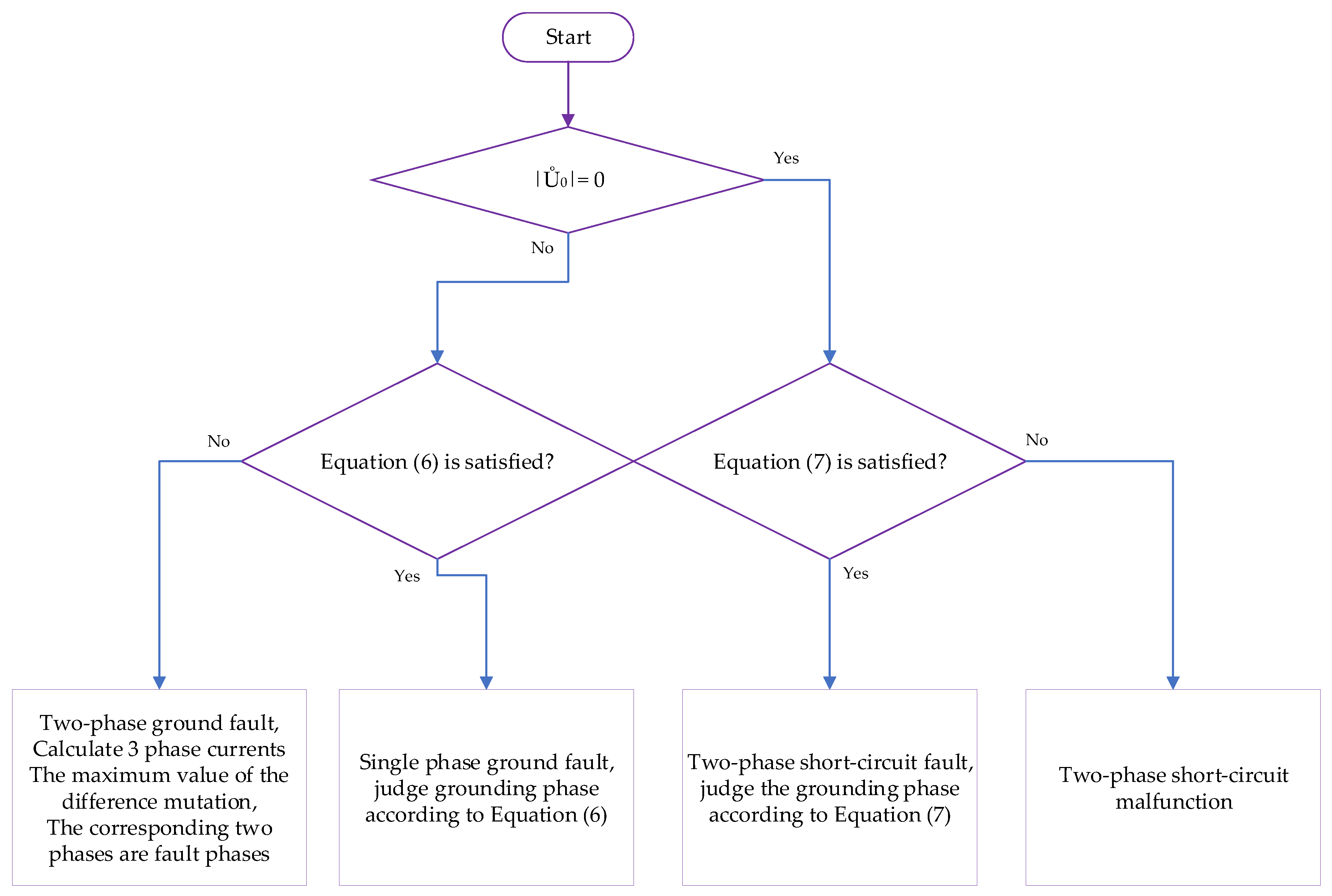
The specific phase selection process is shown in
Figure 2. The phase selection criterion is shown in Equations (6) and (7), where
is generally taken as 4–8 and
is the zero-sequence voltage amplitude.
The photovoltaic power station generally contains a static var generator (SVG), so the photovoltaic power generation unit does not provide reactive power before and after the system failure, as such,
. Combined with Equations (2), (4), and (5), it can be known that the uniform expression of the phase current difference mutation when the transmission line fails is:
where,
Here,
;
,
,
;
is the amplitude coefficient;
is the phase angle of the phase current difference mutation; and
is the active power of the PV unit before the fault.
If the photovoltaic power station adopts the target of suppressing the negative sequence current, then
, and its substitution into Equation (8) can obtain the amplitude relationship of the phase difference of the PV-side (N-side) of the transmission line.
That is, when
, the magnitude of the sudden change in the phase difference of the photovoltaic phase of the sending line is equal. In combination with the phase selection process of
Figure 2, the magnitude relationship of Equation (9) obviously does not conform to the criterion of Equation (6). Therefore, this will result in the incorrect operation of the phase-selective component of the phase-to-phase current difference of the photovoltaic side (N-side) of the outgoing line.
If the photovoltaic power plant adopts the goal of suppressing the active power fluctuation or suppressing reactive power fluctuation, then
or
. This paper analyzes the active power fluctuation as an example, namely
. Then, the magnitude of the abrupt change of the phase current difference on the photovoltaic power station side of the line (N side) is:
where,
Equation (10) contains many unknown variables, but these variables are fixed at specific moments when a certain fault occurs in the system. The following assumptions are made for analysis:
(1) There exists a grid voltage imbalance , ;
(2) There is also a positive sequence voltage drop depth, .
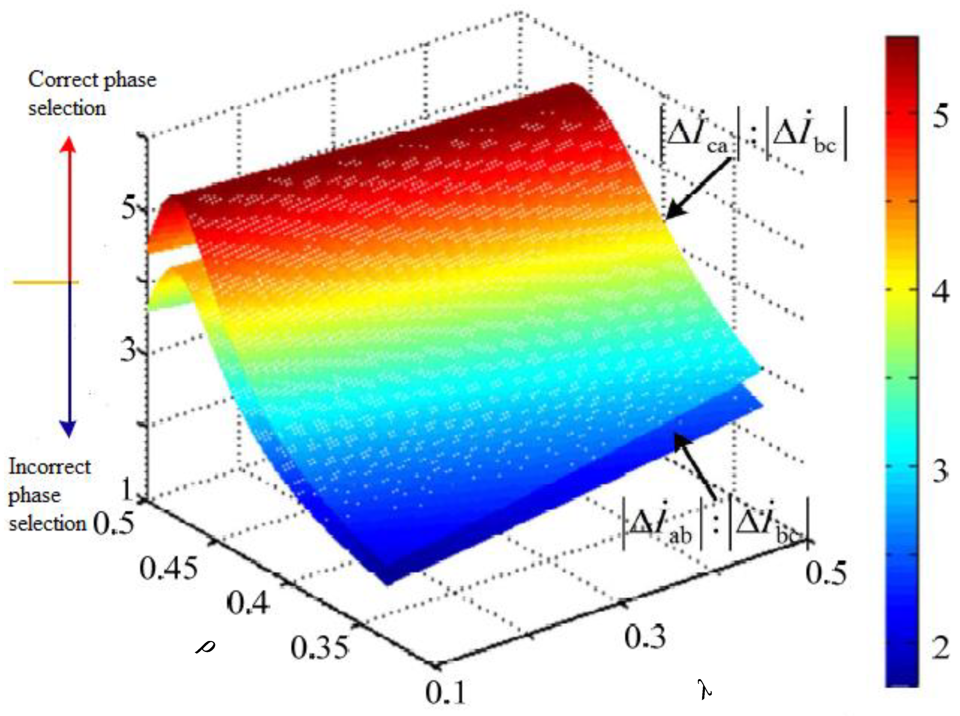
Therefore, the relationship between the
,
and
amplitude ratios and the grid voltage imbalance
and the positive sequence voltage drop depth
can be calculated, as shown in
Figure 3.
When
, it can be seen from
Figure 3 that the amplitude ratio of the abrupt change of the phase current difference was in the range of 2–5, which could be obtained by combining the phase selection process of
Figure 2 and the criterion of Equation (6). As a result, for a partial grid voltage imbalance
the combination of the positive sequence voltage drop depth
(mainly the blue portion in
Figure 3,
) would cause the abrupt change in the phase current difference phase selection component to fail. That is to say, under some conditions, the phase-selective components of the phase current difference of the line photovoltaic power plant may not operate correctly.
In summary, when the transmission line fails, the magnitude relationship of the abrupt change of the phase current difference in the output side of the line is related to the control target and the operating conditions and fault conditions, which may result in failure of the conventional abrupt phase current difference phase selection component to perform the correct action.
4.2. Order Phase Selection Component
The sequence phase selection component is a component that performs fault phase selection by comprehensively comparing the phase and amplitude relationship between different fault current sequence components [
21,
22,
23]. According to the symmetrical component method, the phase difference of the zero negative sequence current and the phase difference of the positive and negative sequence currents under various asymmetrical faults can be obtained, as shown in Equation (11).
Here,
,
, and
are the positive sequence fault component, the zero-sequence component, and the negative sequence component of the fault current, respectively.
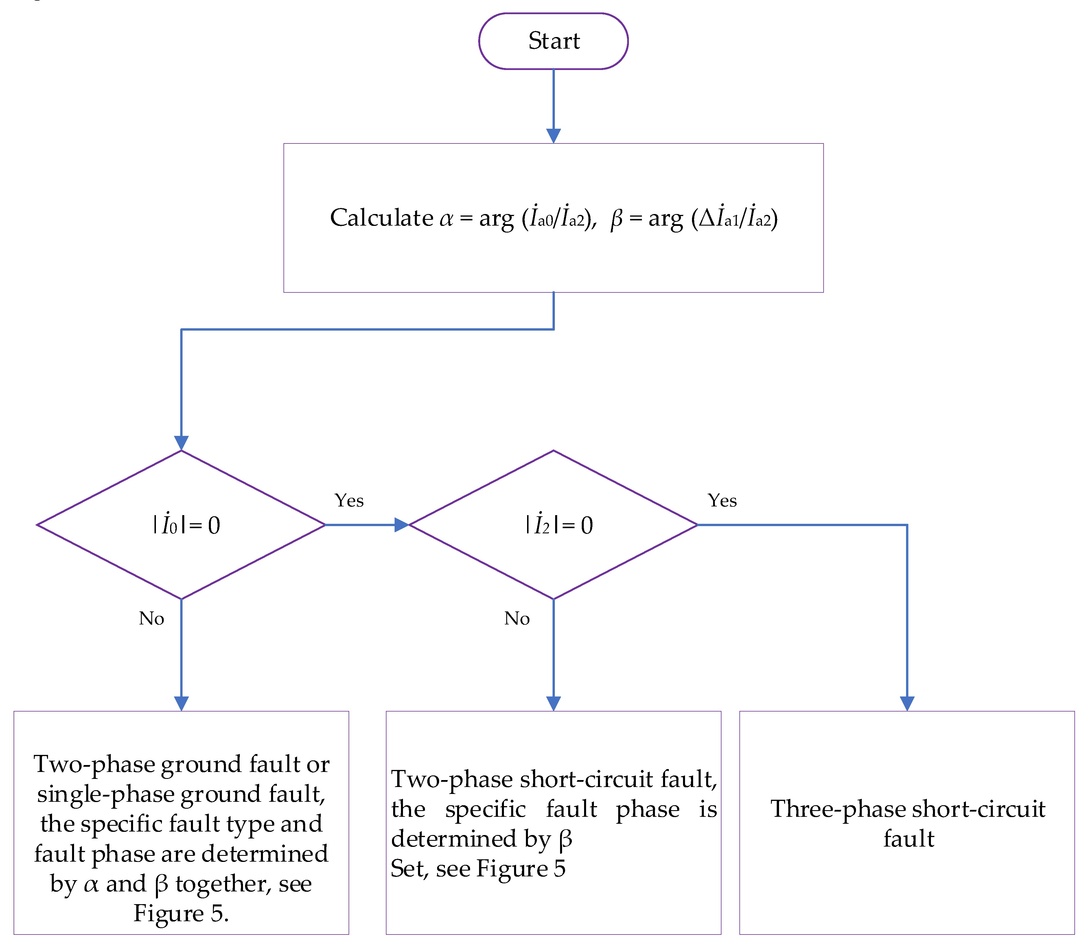
The current sequence component phase selection component option flow chart is shown in
Figure 4 and
Figure 5.
When , the photovoltaic power station adopts the aim of suppressing the negative sequence current, and there is no negative sequence current component in the fault current of the photovoltaic side of the transmission line. The denominator in Equation (11) is zero or very small, resulting in the values of α and β being unstable, and the phase selection component, based on the order component, is inevitably invalid.
When or , the PV grid-connected inverter aims to suppress active fluctuations or suppress reactive fluctuations. Since there is a positive sequence voltage jump angle in β, the following is a classification discussion for .
If the positive sequence voltage jump angle
under certain fault conditions, it can be approximated that
and
, then Equations (2)–(4) can be combined and Equation (11) can be reduced to:
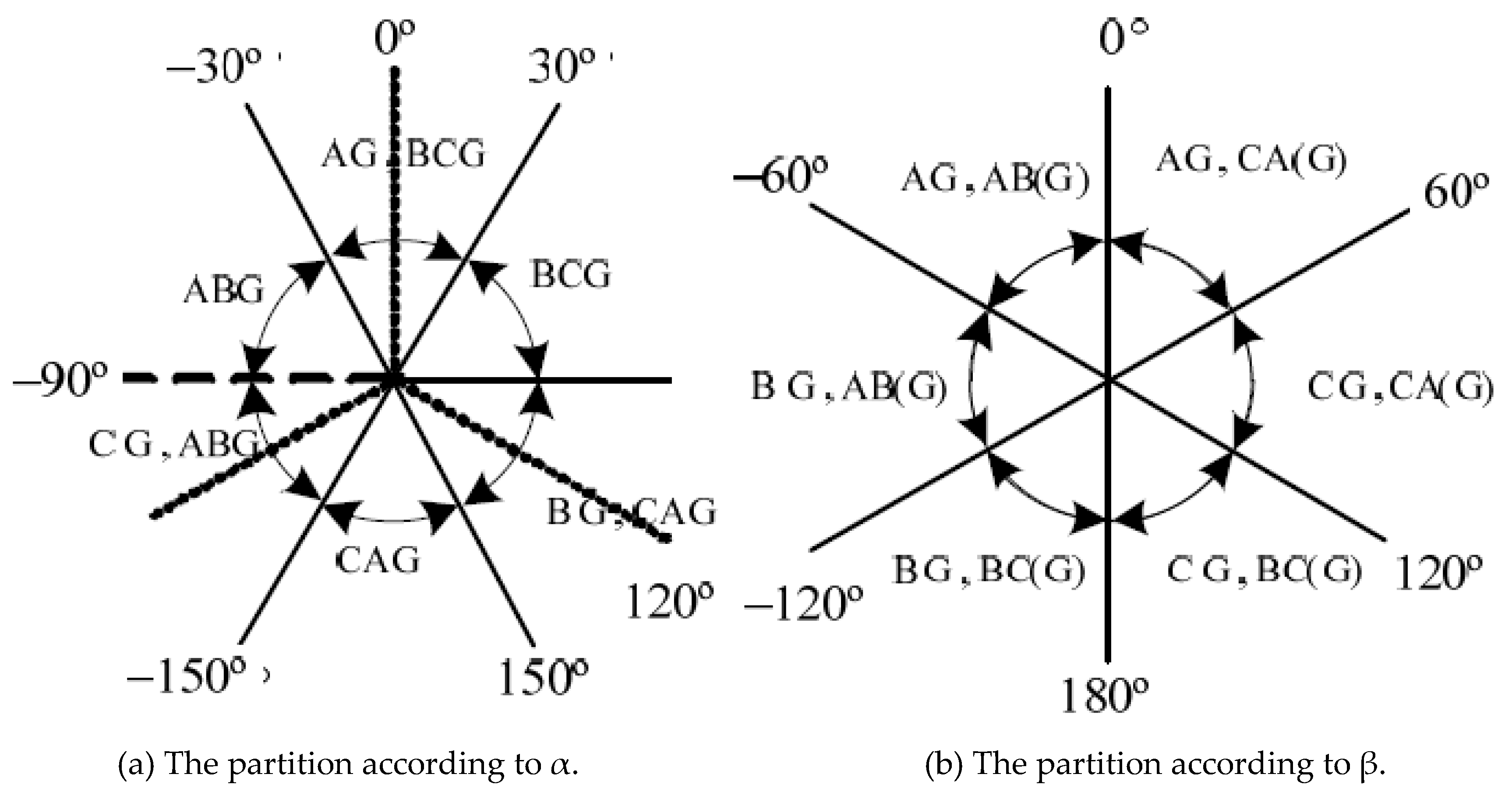
According to the flow chart of
Figure 4, the fault type is determined by α and β, and is obtained by Equation (12). The parameters α and β vary with the fault conditiona and are no longer constant values. Assuming that the BC phase-to-phase short-circuit fault occurs on the sending line, and under certain conditions,
in the phase angle β. If the fault interval is based on the phase selection according to
Figure 5, it is judged that the fault type generated by the outgoing line is a CA phase-to-phase short circuit. This failure causes the phase selection component to fail.
If the positive sequence voltage jump angle
°, Equation (11) can be converted into:
It can be seen from Equation (13) that
α and
β vary with factors such as fault conditions and parameters related to the control strategy. For a specific fault, the phase angle is no longer constant and may result in the incorrect phase selection of the phase selection component.
In summary, when the ground fault occurs in the transmission line, the phase difference of the zero-negative current component and the phase difference between the positive and negative sequence current components are affected by the factors of the fault conditions and control strategy parameters. If you choose the phase selection process according to the process shown in
Figure 4 and
Figure 5, it may lead to traditional order component selection. As a result, the phase element does not operate correctly.
5. Simulation Results
Based on the actual engineering parameters of a 150 MW PV power plant, the simulation model shown in
Figure 1 was built in PSCAD/EMTDC: The PV power plant capacity was 150 MW; a total of seven collection lines of 35 kV were included, and the main transformer rated capacity was 200 MVA, with a rated transformation ratio of 230:37 kV, an YNd11 wiring group, a short circuit impedance of 16%; a delivery line voltage level of 220 kV, a line length of 5.334 km, and with positive sequence and zero-sequence impedances of 0.107 + 0.427 Ω/km, 0.535 + j1.153 Ω/km, respectively. The system equivalent positive sequence impedance was 0.4 + j6.972 Ω, and the equivalent zero-sequence impedance was 0.7 + j10.95 Ω.
To test the performance of the two-phase selection components, this paper set the fault type to a phase A ground fault at F, with a fault start time of t = 1 s, and a duration of 300 ms.
This paper compared and analyzed the results of simulation waveforms with different control objectives.
Figure 6 shows the low-voltage side of the main transformer under different control targets. The fault current simulation waveforms, shown in
Figure 6a–c, were the simulation of currents corresponding to suppressing a negative sequence current, suppressing active fluctuation, and suppressing reactive fluctuation flow waveforms, respectively. It can be seen from
Figure 6a that, since the suppression of a negative sequence current control was taken as the target, the fault current of the main transformer on the low voltage side was balanced by three phases, and was limited by the current limiting section of the photovoltaic inverter. Overall, the current increase corresponded to normal operation, with a current amplitude of about 1.1 times the baseline current.
It can be seen from
Figure 6b,c that if the active fluctuation or the reactive power fluctuation was suppressed as the control target of the inverter control strategy during the fault period, the main transformer three-phase output current on the low-voltage side was unbalanced. Under these conditions, the magnitude of the fault current was significantly higher than the magnitude of the fault current corresponding to the control target of suppressing the negative-sequence current. If the current limiter was included in the photovoltaic power station, the targets of suppressing the active fluctuation or suppressing the reactive fluctuation cannot be achieved. According to the above analysis, the actual photovoltaic grid-connected inverter often adopted a control target of suppressing the negative sequence current to prevent the overcurrent from damaging the power electronic switching device and improving the safety of the inverter operation.
Therefore, the subsequent simulation primarily studies the analysis of the adaptability of the two-phase phase selection components by suppressing the negative sequence current as the control target.
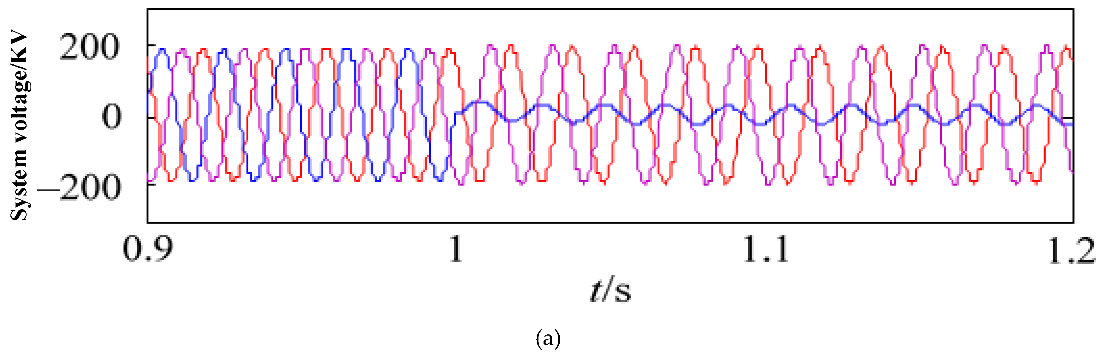
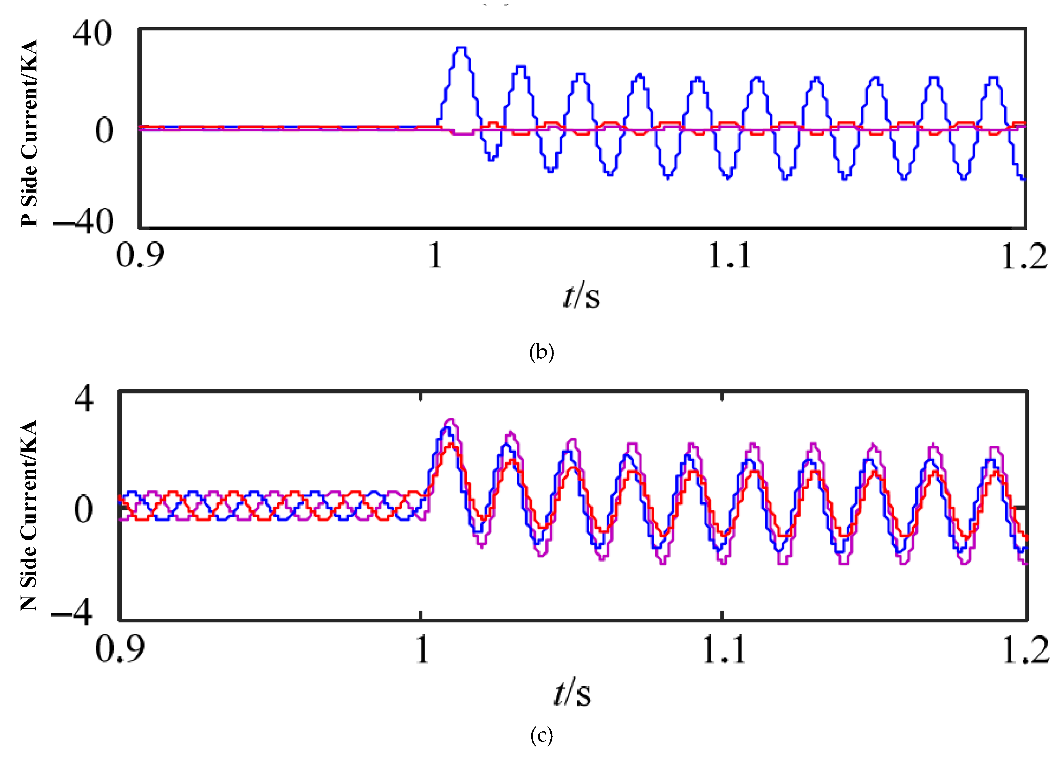
Figure 7 shows the system voltage and fault current waveforms on the transmission line of the PV power plant.
Figure 7a–c, respectively, show the fault current of the grid three-phase voltage and the line system side (P-side), when the A phase is grounded, and the fault current of the photovoltaic side (N-side).
It can be seen from
Figure 7b,c that the amplitude of the fault phase (phase A) on the P side was significantly larger than the current amplitude of the non-fault phase (two phases of BC), and the amplitudes and phase differences of the fault current on the N-side were not obvious. According to the previous analysis, since the photovoltaic system had weak feed characteristics and the N-side main transformer adopted the YNd wiring group, the zero-sequence impedance of the photovoltaic side (N-side) was small, and the zero-sequence current component was mostly in the three-phase fault current. Therefore, phase A grounding occurred at the outgoing line F. When the fault occurred, the three-phase current characteristics of the photovoltaic side during the fault were of approximately the same phase of the same amplitude, which was more obvious than the fault current characteristics in the traditional power grid.
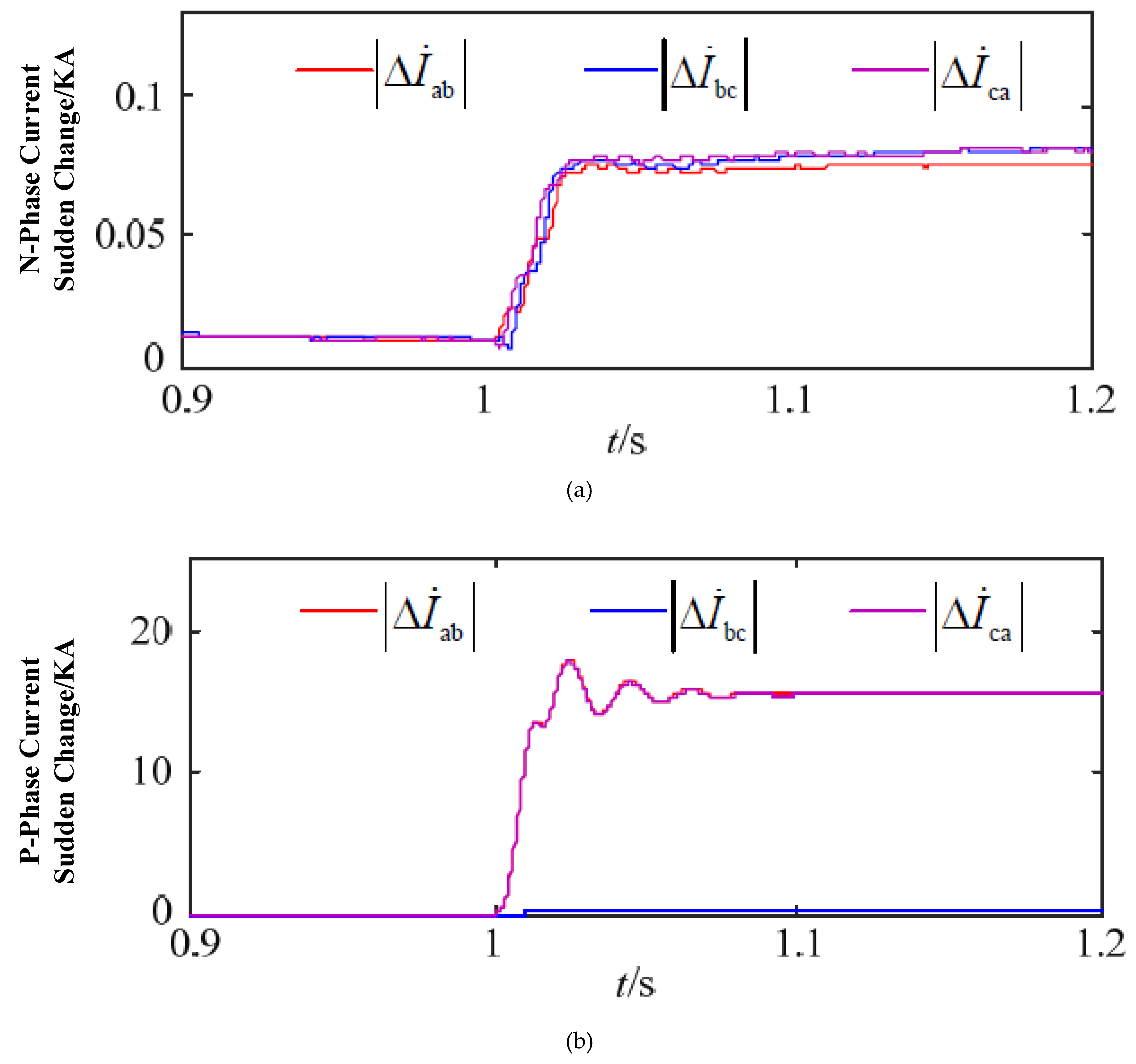
To verify the amplitude relationship of the phase current difference of the N-side phase of the sending line of Equation (9),
Figure 8 shows the amplitude relationship of the phase-to-phase current difference of the phase A ground fault at 1 s. It can be seen from
Figure 8 that when the phase A ground fault occurred, the magnitude of the abrupt change of the phase current difference on the N-side, due to the control strategy of the photovoltaic power station and the main transformer wiring method
were substantially equal, consistent with Equation (9). This scenario apparently did not satisfy the phase selection criterion (6) of a phase A ground fault, resulting in the incorrect operation of the phase selection component; for the system side, the photovoltaic power plant, accessing the positive and negative sequence fault current characteristics, had little effect, so the phase difference of the phase current difference in the system side still conformed to the phase selection process shown in
Figure 2, and the phase selection component could correctly select the phase.
Figure 9 shows the positive and negative zero-sequence components and their phase angle waveforms when phase A was grounded. According to
Figure 9a, when the phase A ground fault occurred at the outgoing line F, the zero-sequence current component flowing through the photovoltaic side (N-side) was much larger than the positive sequence current component, and the negative sequence current component was close to zero. It can be seen from
Figure 9b that the negative sequence current component was extremely small, such that the values of
α and
β could not be stabilized, which led to the phase difference and the positive phase of the negative fault component of the photovoltaic side (N-side). The phase difference of the negative sequence fault component; thus, had uncertainty. Therefore, the phase component selection of the photovoltaic side (N-side) could not meet the phase selection process conditions in
Figure 4 and
Figure 5, which would cause the conventional sequence phase selection component to fail.
When the photovoltaic power station suppressed the negative sequence current, as the control target in the grid-connected inverter control strategy, the phase selection of the abrupt change of the phase current difference and the sequence component of the N-side and the P-side proceeded according to the phase selection flow of
Figure 2 and
Figure 4. The phase selection results of the components were analyzed, as shown in
Table 1. It can be seen that whether the abrupt change of the phase current difference phase selection component or the sequential component phase selection component was used, there was a possibility of phase selection failure on the photovoltaic power plant side.
6. Conclusions
Based on the fault current characteristics of the large-scale photovoltaic power station transmission line, this paper analyzes the adaptability of the abrupt change in the phase current difference and the sequence component phase selection components in the protection of the PV power plant side. The conclusions are as follows: (1) The characteristics of the fault current on the side of the PV power station are obviously different from those of the traditional power supply. The former is related to the PV inverter control strategy, active and reactive commands, fault type, voltage drop depth, and other factors, while the latter is mainly driven by synchronous power generation. It means that the PV power generation quality depends on inverter design, active and reactive power elements characteristics, different fault attributes, light intensity, orientation, voltage and current levels, while the traditional power generators depend mostly on synchronization of power generation units that are inter-networked together. The fault characteristics of the machine are affected. (2) For the protection of the photovoltaic power station side, whether it is the abrupt change of the phase current difference phase selection component or the sequence component phase selection component, the phase selection failure will be adopted when the suppression of the negative sequence current control strategy is adopted. When this strategy is used, suppression of the active power fluctuation or reactive power is adopted. When the wave control strategy is used, the phase selection will fail under certain conditions. (3) The system side phase selection components are not affected by the photovoltaic power station and can be correctly selected. The proposed work has advantages for the end users, such as adaptive protection of solar PV power, which will prevent the loads connected to it. It will provide smooth power delivery to the end users. Furthermore, the proposed work points out the irregularities in the power line, and by overcoming this issue, the user can be given smooth power supply. This work also gives performance indicators for various faults, which, after reducing, has significant performance improvement for the end users’ connected loads. This research work can further be extended as future work by incorporating solar PV grid synchronization, impact of transients on the system performance, ripples alleviation in energy conversion, and the impact of harmonics injection.


