The advantage of PFAC is avoidance of boundary detection by removing backward state transitions in the traditional AC algorithm. However, the PFAC algorithm still experiences load imbalance because attack patterns are with different lengths and every thread begins its pattern matching from a unique position in the input stream. If the pattern that is being matched by a thread is longer, the other threads in the same warp might have gradually become idle after finishing their matching, resulting in severe branch divergence and low usage of warps that together degrade system performance significantly. To address the problem, in this section we introduce the two-phase PFAC algorithm that can increase the usage of GPU resources and reduce the overall execution time.
3.1. Primary Idea
The performance issues of the PFAC algorithm are as follows. (1) Although PFAC creates huge amounts of threads, most threads have a high probability of terminating very early because of no failure transitions in its finite state machine, resulting in severe branch divergence and low GPU hardware utilization. (2) The state machine is too large to fit into the faster shared memory in a CUDA GPU. Instead, the finite state machine is stored in either the global memory or the texture memory, resulting in high-latency memory accesses and slow-speed state transitions.
We analyze the first performance issue more detailed by running the PFAC algorithm with the rule set of Snort version 2.9. The first experiment runs different input sizes to observe how many threads terminate their execution after a certain number of state transitions as shown in
Table 1. Approximately 60% of the threads were idle after the first match when the input sizes are less than or equal to 32 MB, and more than 70% of the threads became idle if the input size are larger. If the PFAC algorithm performs one more matching, 82.26% to 96.31% of the threads terminated their executions because of failure matching. Finally, less than 1% of the threads required matching more than five times for all cases, indicating that only a small number of threads were active after five matchings. Furthermore, the active threads were actually distributed among different warps and each warp had only a small number of active threads.
Table 2 shows the ratios of warps with less than 3 active threads in execution after five matchings. Note that there are totally 32 threads in each warp. More than 97% of the warps had one or two active threads that require further execution after five matchings, meaning the utilization ratio of each individual of the warps is quite low.
Because above 97% of the warps have less than 3 threads in execution after five matchings, the PFAC algorithm has a severe load imbalance problem. In other words, more and more threads become idle when they proceed to next states due to mismatches. Since a CUDA GPU adopts a single instruction, multi-threading parallel execution model and a warp is scheduled dynamically for execution at a streaming multiprocessor at a time, all the threads in a warp perform a same instruction with different data during each cycle. If a thread fails on an if-statement without an associated else-statement, it becomes idle if there are any active threads requiring to execute the codes in the body of the if-statement. Moreover, idle threads have to wait for active threads in the same warp before all the threads meet at the next convergence point. Consequently, the execution time of a warp is equal to the execution time of the last thread to complete its task and it is independent with execution times of other warps. The total execution time of a thread block is equal to the summation of execution times of all the warps in the block.
We use the example shown in
Figure 2 to explain the load imbalance in the PFAC algorithm because each thread will execute different numbers of letter matchings in the same warp. In this example, there are two warps and each warp consists of 32 threads. Each warp has only one thread that requires further matching after five matchings of letters, which the common case as implied in
Table 1 and
Table 2. The number of idle threads is increased whenever one more state transition is made. As a result, the utilization ratio of each warp decreases when we proceed to subsequent matchings. Since the warp will be executed in interleaving, the total execution time for these two warps is equal to (T1 + T2 + T3 + T4).
To minimize the total execution time of a thread block, it is best to allocate the matchings of similar workloads to warps as few as possible. However, it is impossible to have the information about the workload of each matching before actual execution. Therefore, we proposed a two-phase PFAC algorithm to address this problem. In the first phase, a thread will proceed to next states one by one as far as
Y state transitions at most if no mismatch occurs, where
Y is a threshold that can be predefined by users. The value of Y should be very small in terms of the experimental results shown in
Table 1 and
Table 2. At the end of the first phase, all the active threads, distributed among different warps in the same block, will be merged into a few of warps and perform further pattern matching in the second phase. It can be expected that the number of active threads at the end of the first phase is much smaller than the total number of threads in the block. Consequently, only a very few number of warps will be executed in the second phase actually and each of these merged warps except the last one has 32 threads at the beginning of the second phase. That is, the two-phase PFAC algorithm can increase the usage of warps and make most warps idle as soon as possible, resulting in a reduced execution time. Therefore, the problem of branch divergence can be alleviated and a better system performance can be obtained.
We use the example shown in
Figure 3, the same as that shown in
Figure 2, to give the main idea of our proposed two-phase PFAC algorithm. The threshold is set five based on the experimental results shown in
Table 1 and
Table 2. In the first phase, the pattern matchings are executed in the same way as that proposed by the PFAC algorithm. However, at most five letters are matched in this phase. Warp 0 and Warp 1 requires execution times of T1 and T3, respectively. Before proceeding to the second phase, Thread
t1 in Warp 0 and Thread
t62 in Warp 1 are merged into Warp 0. In the second phase, these two matchings will be executed by the first two threads in Warp 0 in parallel and the required execution time is the minimum of T2 and T4. As a result, the total execution time of the two-phase PFAC algorithm is (T1+ T3 +
min (T2, T4) + T
m), instead of (T1 + T2 + T3 + T4) that is required in the PFAC algorithm, where T
m represents the overhead of merging threads inside each block. The execution time difference between the two-phase FPAC algorithm and the PFAC algorithm increases when there exists one longer matching. The execution time difference becomes larger when the matched pattern is longer.
3.2. Implementation
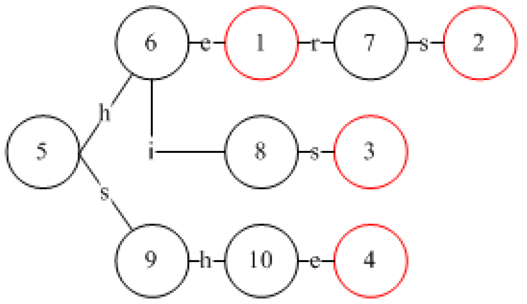
We use an example with six patterns, as shown in
Figure 4, to detail how to implement the proposed two-phase PFAC algorithm on a CUDA GPU. Based on the given six patterns, the corresponding PFAC state machine is constructed and illustrated in
Figure 4. Because the first and second patterns have the same prefix string of three letters, these two patterns share the same state transitions for the first three letters. In other words, an input stream with a prefix of “cha” will lead to State 10 no matter what the suffix of the input stream is. However, because the fourth letters of these two patterns are different, there are two transitions leaving from State 10. If the fourth letter is “n”, the state machine will transit to State 11 but “r” will lead to State 14.
Traditionally, one table is used to record the information about all state transitions for a state machine and the table is so large that it cannot be fit into the small but faster shared memory on a CUDA GPU. Consequently, the state transition table is stored in either the global memory or texture memory. To address the problem, we divide the state transition table into two tables and they are the Prefix PFAC Table and Suffix PFAC Table. The first table should be small enough to be stored in the faster shared memory while the second table is kept in the global memory or texture memory.
The
Prefix PFAC Table, as shown in
Table 3, records the state transitions only for the first two letters of the six patterns. This table is constructed as a 128*128 two-dimensional array and each dimension can be indexed by a letter. Each cell contains an integer number representing the next state. State 0 is reserved to represent a trap state, indicating a mismatch and that the responsible thread terminates immediately. For example, if the first two letters in the input stream are “ch,” we can find the next state by looking up the table slot whose column index and row index correspond to the ASCII codes of “c” and “h”, respectively. Therefore, the next state for the first two letters, “ch,” is State 9. Similarly, if the first two letters are “fo,” the next state is State 20. Because the maximum state number is less than 65536, each state number can be encoded with two bytes. Since the size of the Prefix FPAC Table is 128*128, the total memory size of the
Prefix PFAC table is 32 KB, which can be fit into the much faster shared memory whose size is 48 KB in Tesla K20 and GTX TITAN X.
The Suffix PFAC Table is similar to the state transition table used in the PFAC machine proposed by Lin et al. except that the entries corresponding to the first two letters are eliminated, resulting in a smaller table that is stored in the global memory. The Suffix PFAC Table is also a two-dimensional array but the organization is different from the Prefix PFAC Table. Each row in the Suffix PFAC Table corresponds to a next state while each column corresponds to a letter. Each slot contains a next state and it can be accessed with the current state and the input letter. The Suffix PFAC Table is accessed only when the next state in the Prefix PFAC Table is not State 0, where the next state is determined by the first two letters in the input stream.
Figure 5 shows the initial state traversal algorithm of the first phase in the two-phase PFAC algorithm. We assigned each letter in the input stream to a thread as its starting letter for matching. In other words, the
i-th letter in the input stream will be assigned to the thread with a global thread id equal to
i. For example, if input size is 32 MB, the total number of threads required is 32*1024*1024. We can set the number of blocks and the number of threads to 32,768 and 1024, respectively. Therefore, the number of blocks is 32,768, recorded with the system variable
GridDim.x, and the number of threads per block is 1024, recorded with the system variable
BlockDim.x. The thread id,
ThreadIdx.x, in each block ranges from 0 to 1023, and the block id,
BlockIdx.x, ranges from 0 to 32,767. The global id,
global_id, of a thread can be obtained by the following formula:
The index of the first letter to be matched by a thread with an id of ThreadIdx.x is equal to global_id.
To resolve the load imbalance problem, we use a threshold to limit the maximum number of letters to be matched in the first phase. Because, for an input size of 32 MB, less than 1% of the threads requires further matching after 5 matchings, as shown in
Table 1, the threshold is set to 5.
We use an Input array to represent the input stream, strIndex, a local variable, to represent the index of the current letter in Input to be processed by a thread, and next_state to record the next state. The initial value of strIndex is set to the index of the starting position in the input stream for the corresponding thread. The initial value of the current state is set as INITIAL_STATE whose state number is equal to the number of patterns plus one. For instance, if the pattern set is Snort V2.9, the value of INITIAL_STATE is 3863 because the total number of patterns is 3862. After scanning the first two assigned letters, a thread checks the next state by referring to the Prefix_PFAC_Table. If the state number of the next state is less than the value of INITIAL_STATE, it is a final state and recorded in the Output array. Otherwise, the next state is a transition state, the system needs further matching with the subsequent letters and the Suffix PFAC Table. The matching continues until the next state is the TRAP_STATE that is State 0. If the next_state is not equal to TRAP_STATE after the thread is executed to the threshold, implying the requirement of further matching in the second phase, we record set the corresponding element of the Incomplete array to 1; otherwise, 0 is recorded. The Incomplete array is used to record which threads have not been completed their matchings that will be processed in the second phase.
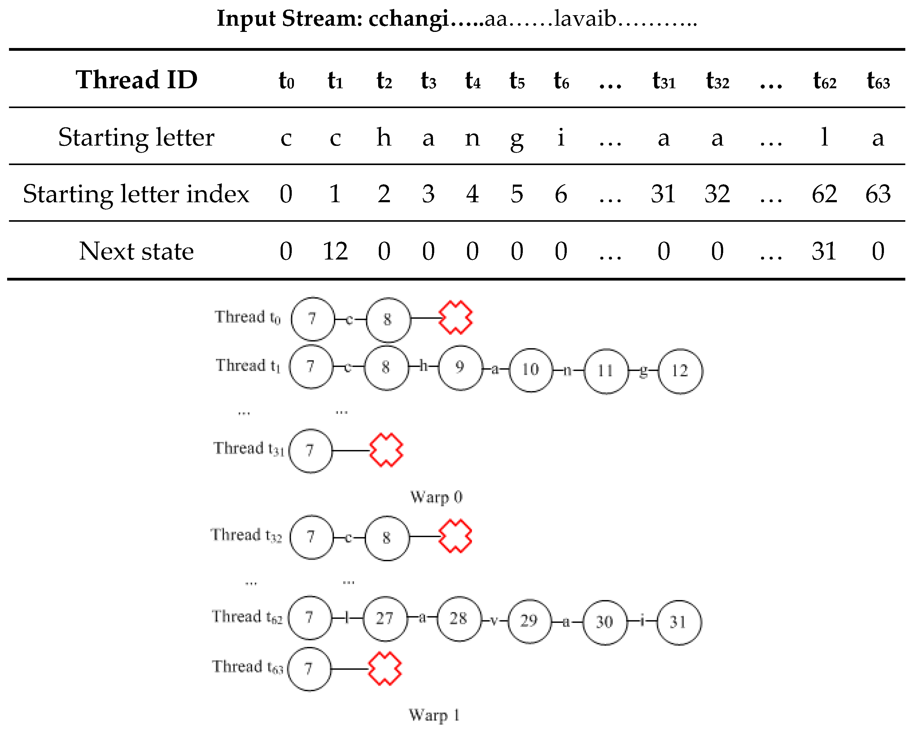
Figure 6 shows the next states for each thread after reaching the threshold of the two-phase PFAC algorithm, which is set to 5. Assume the input stream is: “cchangi…..aa……lavaib………..,” each letter is assigned to each thread one by one. For instance, Thread t
0 scans the input stream from the beginning of the input stream, i.e., the letter “c,” and Thread t
2 scans the input stream from the third letter of the input stream, i.e., the letter “h.” Since the first two letters are “cc”, Thread t
0 reaches a trap state after looking up the Prefix PFAC Table, meaning that there is no need to proceed to further comparison. For matchings that fail in the first phase are referred to as
failure-search matchings. On the other hand, based on the information stored in the Prefix PFAC Table, Thread t
1 will reach to Sate 9 because the first two letters for it are “ch,” indicating that it is possible to have a match and further comparison is required. Thread t
1 will use its third letter, “a,” to lookup the Postfix PFAC Table for its next state and it is State 10. Next, Thread t
1 continues its matching with the fourth and fifth letters, “ng,” to find the next states one by one. After these matching, Thread t
1 reaches to State 12 and it requires further comparison. Because at most five letters will be matched in the first phase in the two-phase PFAC algorithm, we need to record the index of the fifth letter for Thread t
1 in the input stream and the next state after five matches before proceeding to the next phase of the PFAC algorithm. However, we record the thread id instead of the index of the next letter to be matched because we can easily have the index by adding five to the thread id. For the matchings requiring further comparison in the second phase are called
continued-search matchings. In the second phase, we only need to process the continued-search matchings. In this example, only the matchings assigned to Threads t
1 and t
62 belong to this category in the first two warps. In other words, only two threads remain active after five matches and in fact each warp has only one active thread at the end of the first phase, which incurs a severe branch divergence and load imbalance.
We will merge the continued-search matchings in the same block into warps as few as possible before proceeding to the second phase and we call this merging the job compression procedure. In this case, these two continued-search matchings can be merged into a single warp, leaving the second warp idle. Consequently, we need to perform a job compression process before going to the second phase. To perform the job compression procedure, we need to record the information about the continued-search matchings running by active threads. An Incomplete array is allocated to indicate whether the corresponding matching is completed or not, as described previously. In addition, the starting position for the subsequent execution of each continued-search matching is stored in the nextLetterIndex Array in the shared memory.
To perform the job compression procedure, if there are
k continued-search matchings in a block, we will let the first
k threads in the block be responsible for executing the further matchings in the second phase. We use the first two warps for explanation. We need to perform a parallel reduction operation on the
Incomplete array to have the prefix sum [
37] for each element, indicating the information about how many active threads before and including itself for each thread. We use the example shown in
Figure 6 to explain the idea and the results are shown in
Table 3 and
Table 4. For instance, since Thread
t1 is the first active thread, its prefix sum is 1 while the result for Thread
t0 is 0, as shown in
Table 3. Similarly, Thread
t62 is the second active thread and its prefix sum is 2. Moreover, the prefix sum for each thread between
t1 and
t62 is 1. Based on the corresponding prefix sum and Incomplete value, the
i-th active thread whose Incomplete value is 1 can write the index of its next letter and the next state to the
i-th elements in the corresponding arrays to be processed in the second phase. For instance, Thread
t1 will write its next state, State 12, and the next letter index to the first elements in the two arrays,
newStrIndex and
newState, which are used by Thread
t0 in the second phase, as shown in
Table 3. Since the next letter index can be obtained by adding the thread id and the threshold value, i.e., 1 + 5 = 6, we record the thread id instead, as shown in
Table 4. Similarly, Thread
t62 will write its next state, State 31, and its thread id, 62, to the second elements in the two arrays that will be used by Thread
t1 in the second phase. In this example, in the second phase, only the first two threads in the first warp will perform the further matching procedure because their next states are not equal to State 0, i.e., trap state. In this way, the continued-search matchings are merged into the first warp and executed by Threads
t0 and
t1, alleviating the impacts of load imbalance and branch divergence.
Figure 7 shows the algorithm of the job compression procedure, where the parallel reduction is the similar to that in [
37].
Figure 8 shows the second phase algorithm of the two-phase PFAC algorithm. The second phase is based on the results calculated in
Table 4. Each thread will check its newStrIndex value to determine whether it needs execution of further matching in the second phase. It the value is not equal to −1, the thread will use the result of adding the threshold value to the newStrIndex value to have the correct letter index for the subsequent matching. In addition, the thread will read its newState value to access the Suffix PFAC Table for retrieving the next state. For instance, Thread
t0 will add 5 to its newStrIndex value, i.e., 1, to have the correct letter index 6 for its subsequent matching, as shown in
Table 5. In addition, its next state is equal to 12 that is stored in the first element in the newState array, as shown
Table 5. Similarly, Thread
t1 will add 5 to its newStrIndex value of 62 to have the correct letter index 67 for its subsequent matching and its next state is equal to 12 that is stored in the first element in the newState array. On the other hand, all the other threads will not execute any matching because their newStrIndex values are equal to −1. As a result, the second warp keeps idle during the whole second phase.


