Article

Design of Fuzzy-PI and Fuzzy-Sliding Mode Controllers for Single-Phase Two-Stages Grid-Connected Transformerless Photovoltaic Inverter

1
School of Electrical Engineering, Pusan National University, Busandaehak-ro 63beon-gil, Geumjeong-gu, Busan 46241, Korea
2
School of Electrical Engineering and Computer Science, National University of Sciences and Technology, Islamabad 44000, Pakistan
3
Department of Engineering, Federal University of Santa Catarina Blumenau, 2750-89036-256 Rua João Pessoa, Brazil
*
Author to whom correspondence should be addressed.
Electronics 2019, 8(5), 520; https://doi.org/10.3390/electronics8050520
Submission received: 12 April 2019 / Revised: 3 May 2019 / Accepted: 7 May 2019 / Published: 9 May 2019
(This article belongs to the Special Issue Grid Connected Photovoltaic Systems)

Abstract

:
Conventional Energy Resources (CER) are being rapidly replaced by Renewable Energy Resources (RER) due to their abundant, environmentally friendly, clean, and inexhaustible nature. In recent years, Solar Photovoltaic (SPV) energy installation is booming at a rapid rate among various RER. Grid-Connected PVS required advance DC-link controllers to overcome second harmonic ripple and current controllers to feed-in high-quality current to the grid. This paper successfully presents the design of a Fuzzy-Logic Based PI (F-PI) and Fuzzy-Logic based Sliding Mode Controller (F-SMC) for the DC-link voltage controller and Proportional Resonant (PR) with Resonant Harmonic Compensator (RHC) as a current controller for a Single-Phase Two-Stages Grid-connected Transformerless (STGT) Photovoltaic (PV) Inverter. The current controller is designed with and without a feedforward PV power loop to improve dynamics and control. A Second Order General Integral (SOGI)-based Phase Lock Loop (PLL) is also designed that has a fast-dynamic response, fast-tracking accuracy, and harmonic immunity. A 3 kW STGT-PV system is used for simulation in Matlab/Simulink. A comparative assessment of designed controllers is carried out with a conventionally well-tuned PI controller. The designed controllers improve the steady-state and dynamic performance of the grid-connected PV system. In addition, the results, performance measure analysis, and harmonics contents authenticate the robustness, fastness, and effectiveness of the designed controllers, related to former works.

1. Introduction

Diminishing fossil fuel reserves and global environmental concerns enhance the urgency of transitioning towards sustainable energy resources due to their abundant, environmentally friendly, clean, and inexhaustible nature [1]. In the last several years, the installation of Photovoltaic (PV) is booming at a rapid rate and will play a vital role in the future mixed power grid [2,3]. The energy forecast of 2020 shows that the installed capacity of solar PV (772 GW) will lead to wind energy (735 GW) [4]. Mainly a majority portion of single-phase inverters is connected to the grid [5]. A power electronics voltage source inverter is used as an interface for a PV system to the distribution grid.
The controllability of the grid-connected PV system due to its variable nature is a challenging task. Additionally, the grid standards must meet when connecting to the grid. The purpose of these grid codes is to acquire robustness, high quality of injected grid power, and fast control [6]. A typical PV system consists of two stages with separate control, i.e., input sided-DC converter and output side DC-AC inverter [7,8]. The DC-DC converter is used to extract maximum power and to achieve Maximum Power Point Tracking (MPPT) while the DC-AC inverter is used to effectively transfer the extracted power to the distribution grid [9]. The DC-link capacitor voltage must be regulated to achieve this. The DC-link capacitor has many functions, i.e., it acts as an energy storage capacitor, to limit fluctuations in the input dc voltage of the inverter, to reduce ripple, and to provides the flexibility to alternate the instantaneous power in between the two stages [10]. Furthermore, the DC-AC inverter stage also performs other significant responsibilities, i.e., reactive power compensation, synchronization, islanding detection, injecting high quality current to the grid, low/high-frequency ride through, and low/high voltage ride through and other ancillary functions [11]. The characteristics of power quality for the PV system are measured and assessed by various parameters, i.e., slow voltage variations, unbalance, flicker, and harmonics [12].
Recently, Grid-Connected Transformerless (GT) PV inverters, i.e., 1–10 kW, are gaining wide acceptance. In comparison to inverters based on transformer galvanic isolation, the promising features of GTPV inverters are: Lower cost, lighter weight, smaller volume, higher efficiency, and less complexity. The “race” for higher efficiency PV inverters has resulted in a large variety of “novel” transformerless topologies derived from H-bridge and Neutral Point Clamped (NPC) topology with higher efficiency and lower Common Mode/Electro-Magnetic Interference [4]. Though the GTPV has many advantages, the high leakage current is the main concern. Various aspects, problems, and future trends of GTPV inverters are reported in References [4,13]. In Reference [14], a detailed analysis of DC current injection and the problems that can occur is carried out.
Many researchers have focused on grid-connected inverters to effectively transfer energy generated from the PV system. Some of these focused areas are inverter topologies, control schemes, controller design, etc. Typically, the current control loop can be implemented in the three-phase natural reference frame (abc), the stationary reference frame ( α β ), and the rotating reference frame (dq). To control steady-state and transient performance of grid-connected PV system, various controllers are investigated as: Repetitive Controller (RC) and Proportional Resonant (PR) controller with parallel RESonant (RES)-based harmonic compensators [15], Sliding Mode Controller (SMC), deadbeat controller [15,16,17,18,19,20,21,22,23,24], hysteresis controller, and Proportional Integral (PI) controller with grid voltage feedforward [25,26,27,28,29,30]. In addition, neuro-fuzzy and fuzzy logic based on artificial intelligence methods, adaptive controllers, and neural networks are also proposed in References [31,32,33,34].
In Reference [15], a frequency adaptive selective harmonic control is proposed for the grid-connected PV system. An adaptive SMC is designed for cascaded two-level inverter in Reference [20]. In Reference [25], a full digital hysteresis current controller is designed to regulate the current of the grid-connected PV system. A neuro-fuzzy-based DSPAC controller is proposed in Reference [31]. In Reference [34], a grid interactive RE system based on Fuzzy PI is presented. Also, in terms of steady-state error and transient response, the advantages and disadvantages of these schemes have been proposed in the literature. The aforesaid controllers enhanced the performance of the grid-connected PV system. However, these controllers lack the comparative analysis of Fuzz PI, Fuzzy-SMC, and PR with RHC for the STGT PV inverter with and without a feedforward PV power loop.
In light of the above-detailed issues, the key contributions of our paper are:
  • We propose Fuzzy-Logic Based PI (F-PI) and Fuzzy-Logic based Sliding Mode Controllers (F-SMC) for DC-link voltage control.
  • A Proportional Resonant (PR) with Resonant Harmonic Compensator (RHC) is designed as a current controller for the STGT PV inverter.
  • The current controller is designed with and without feedforward PV power loop to improve dynamics and control.
  • A superior SOGI-based PLL is employed that has a fast-dynamic response, fast-tracking accuracy, and harmonic immunity.
  • A comparative assessment of the designed controllers with a well-tuned conventional PI controller on the bases of oscillation, overshoot, undershoot, rise time, settling time, etc.
  • The Total Harmonic Distortion calculation of a periodic grid voltage and grid current based on discrete samples using the PLECS library.
  • Performance index calculation and assessment, i.e., Integral Square Error (ISE), and Integral Absolute Error (IAE) to evaluate the performance of the design controllers.
The rest of the paper is structured as: A two-stage 3 kW grid-connected PV system is proposed in Section 2, and Section 3 comprehensively describes the control loop design and SOGI PLL implementation for a transformerless inverter, the design of F-PI and F-SMC controllers are discussed and designed in Section 4, and the analysis of the results is discussed in Section 5. Section 6 concludes the paper along with a brief proposal for future work.

2. Proposed System Design

The effective operation of the two-stages PV system requires control of various components, i.e., at the PV side for maximum extraction of power, at the inverter side to inject high-quality current (power), and at the grid side for ancillary functions. In the design and planning phase of a PV system, the consideration of ambient temperature and solar irradiance (mission profiles) is mandatory as it affects the PV energy [35,36]. Figure 1 presents the 3 kW two stages single phase grid connected inverter structure. The platform used for implementation is MATLAB®/Simulink®/Simscape R2017b. The specification of the system is given in Table 1.

2.1. DC-DC Converter

In the low power application (i.e., AC-module inverter) the output voltage range of the PV panels/strings is limited, which is the major drawback of single stage inverter, thus affecting the overall efficiency. This issue is solved by double-stage inverter technology. The voltage of the PV module is amplified to the desired level for the inverter stage by DC-DC converter [37]. The MPPT control is performed on the DC-DC converter. Perturb and Observe (P&O) is adopted for simplicity in this research [38]. The MPPT control structure for a boost converter is presented in Figure 2. The P&O algorithm generates the voltage at maximum power point (the reference voltage) for PV panels which is regulated by the Proportional Controller (PC) k m . The value of the PC used is 0.00126 k m [35,39].

2.2. DC-AC Inverter

The grid side control can be implemented in stationary ( α β ) or rotating ( d q ) reference frame [40,41]. The implementation of α β is simple and preferable, but it needs an orthogonal system to produce a “virtual” system that is in quadrature with the real grid. Thus, in this research, the grid-side control is implemented in the α β reference frame. The Second-Order Generalized Integrator (SOGI) Phase Lock Loop (PLL) is utilized to generate the in-quadrature component. The derivation and implementation of SOGI PLL are discussed in the next section. The DC-link voltage is controlled by a PI controller, and PR controller with RHC is used for current control loop as shown in Figure 3 [35]. kpr, kpi, and kpih are the controller parameters. The complete design of current control is discussed in Section 3.

3. Control of Transformerless PV Inverter

3.1. Control Loop Design

Generally, the control of the single-phase grid-connected system consists of two cascaded loops. The outer loop is known as a voltage or power control loop is responsible for generating required current references for the inner current loop. The inner loop is the current loop and is accountable for current protection and power quality issues [42]. According to single phase PQ theory, the active and reactive power is calculated from v α and v β generated by orthogonal signal generator presented as:
P = 1 2 ( v α i α + v β i β ) Q = 1 2 ( v β i α v α i β ) }
where P, Q are the active and reactive powers and v α β , i α β are grid voltage and current in the stationary reference frame, respectively. From Equation (1), the reference current can be generated as:
i α * = 2 ( v α P * + v β Q * ) v α 2 + v β 2 i β * = 2 ( v β P * v α Q * ) v α 2 + v β 2 }
In the above equation ‘ * ’ shows the reference signals. The above equation can be simplified in terms of grid reference current as:
i g * = i α * = 2 v α 2 + v β 2 [ v α v β ] [ P * Q * ]
The implementation of the cascaded dual control loops is shown in Figure 4. The DC-link voltage is controlled using a PI controller. Here, two scenarios are considered as shown in Figure 4. In the first case, the feed-forward PV power Ppv is not used whereas, in second it is employed. The feed-forward PV power Ppv improves dynamic and control performance.
G P I ( s ) / D C l i n k = ( k p + k i s )
where k p and k i are proportional and integral gains. Then the reference for the current control loop is generated using Equation (3). In the grid voltage, there might be distortion; therefore, the controller with RHC is used, as shown in Equation (5). In PR with RHC, multiple resonant controllers are added whose central frequencies are placed at the third, fifth, and seventh harmonics. There valves are k p r = 22 , k p i = 2000 , k p i 3 = 1200 , k p i 5 = 800 , k p i 7 = 200 , respectively [35,43].
G P I ( s ) / C C = ( k p + k r s s 2 + ω 0 2 ) P R + h = 3 , 5 , 7 k i h s s 2 + ( h ω 0 ) 2 R H C

3.2. Second Order Generalized Integrator (SOGI) PLL Design

According to the standards in the grid-connected PV inverter system, the injected current should be in phase with the grid voltage. To cope with the new standards and to correctly generate the reference signal fast and accurate detection of the phase angle, amplitude and frequency are important. Various methods are available in the literature for this purpose, i.e., filtering of grid voltage, zero crossings, and Phase Lock Loop (PLL) method. Most recently, PLL is widely employed in the grid-connected inverter. In literature, there are a large number of PLL based synchronization techniques T/4 Delay PLL [44,45], Enhanced PLL (EPLL) [46], The inverse park transforms PLL, and SOGI PLL [47], etc. Research reveals that in terms of fast dynamic response and high tracking accuracy the SOGI-PLL is a good application for a single-phase grid-connected PV system, in the presence of various disturbances, i.e., frequency variations and voltage sags.
Figure 5 presents the structure of SOGI PLL. Two orthogonal sine waves are generating having 90°, e.g., ( v and q v ). The magnitude and phase of v are the same as that of input v . The transfer function of SOGI is defined as [48,49,50]:
G I = ω s s 2 + ω 2
where the resonance frequency of SOGI is denoted by ω .
H d ( s ) = v v ( s ) = k ω s s 2 + k ω s + ω 2 H q ( s ) = q v v ( s ) = k ω 2 s 2 + k ω s + ω 2 }
In the above equation, the H d ( s ) and H q ( s ) represent the closed loop transfer function, and the bandwidth of the closed-loop system is dependent on k [49]. For the discrete implementation of the orthogonal generation for SOGI PLL, various methods are used, i.e., the trapezoidal method, second-order integrator, and third order integrator [50].

4. Proposed Adaptive Controllers

4.1. Proposed Fuzzy-PI Controller

4.1.1. Fuzzy Controller Architecture

The real-world problems are very complex in nature, and complex problems are basically fuzzy. The advantages of FLC are: They add human deductive thinking to the system and do not rely entirely on exact mathematical models [51]. Their aptitude to deal with uncertainties and non-linearity is also one of the advantages. This makes FLC more competent in applications where existing models are ill-defined, complex, and not sufficiently dependable. The structures of FLC are based on four main parts: Fuzzification, rule-base, inference mechanism, and de-fuzzification, as illustrated in Figure 6 [52].
1. Fuzzification: This is also known as the fuzzifier. It is the input interface step that maps the real or crisp data from the system into a fuzzy set using fuzzy linguistic variables, linguistic terms, and membership functions.
2. Rule Base: A “rule base” contains a set of fuzzy IF-THEN rules with a condition and conclusion. These rules define the action of the controller by controlling the output variable in terms of input variables.
3. Inference Mechanism: This step is also known as fuzzy inference or inference engine. This step deals with how best to control the plant by an expert’s decision making in interpreting and applying the knowledge of rules. It is basically the evaluation and firing of rules.
4. De-fuzzification: This step is also known as de-fuzzifier. It is the output mapping interface that converts the fuzzy input from the inference engine into crisp/real-time output, which is the controller effort to the plant.

4.1.2. Design of Fuzzy-PI Controller

The parameters of the PI controller, i.e., proportional k p and k i integral are constant. When sudden disturbances or parameter uncertainties occurs in the system, the performance of the PI controllers detunes and degrades. Therefore, the adaptive PI controller is required that adjusts its parameters according to the error function [52]. In this controller, fuzzy rules are employed in the PI controller presented in Table 2 and listed as:
(1)
If the error absolute | e ( t ) | is zero, then k p is large and k i is small.
(2)
If the error absolute | e ( t ) | is small, then k p is large and k i is zero.
(3)
If the error absolute | e ( t ) | is large, then k p is large and k i is large.
The Gaussian membership function is employed in the rules that depend on the center c i and standard deviation or variance σ i as:
μ ( x ) = e x p ( 1 2 ( x i c i σ i ) 2 )
A PI controller can be mathematically expressed as:
v D C * / i g * ( P I ) = K p e ( t ) + K i e ( t ) d t
where k p and k i are proportional and integral gains respectively, the input to the controller is e ( t ) , and the output of the controller may be v D C * / i g * . According to Equation (14), the PI parameters are fixed and require adaptation conferring to parameter uncertainties, load disturbances, and electrical faults perturbation [53].
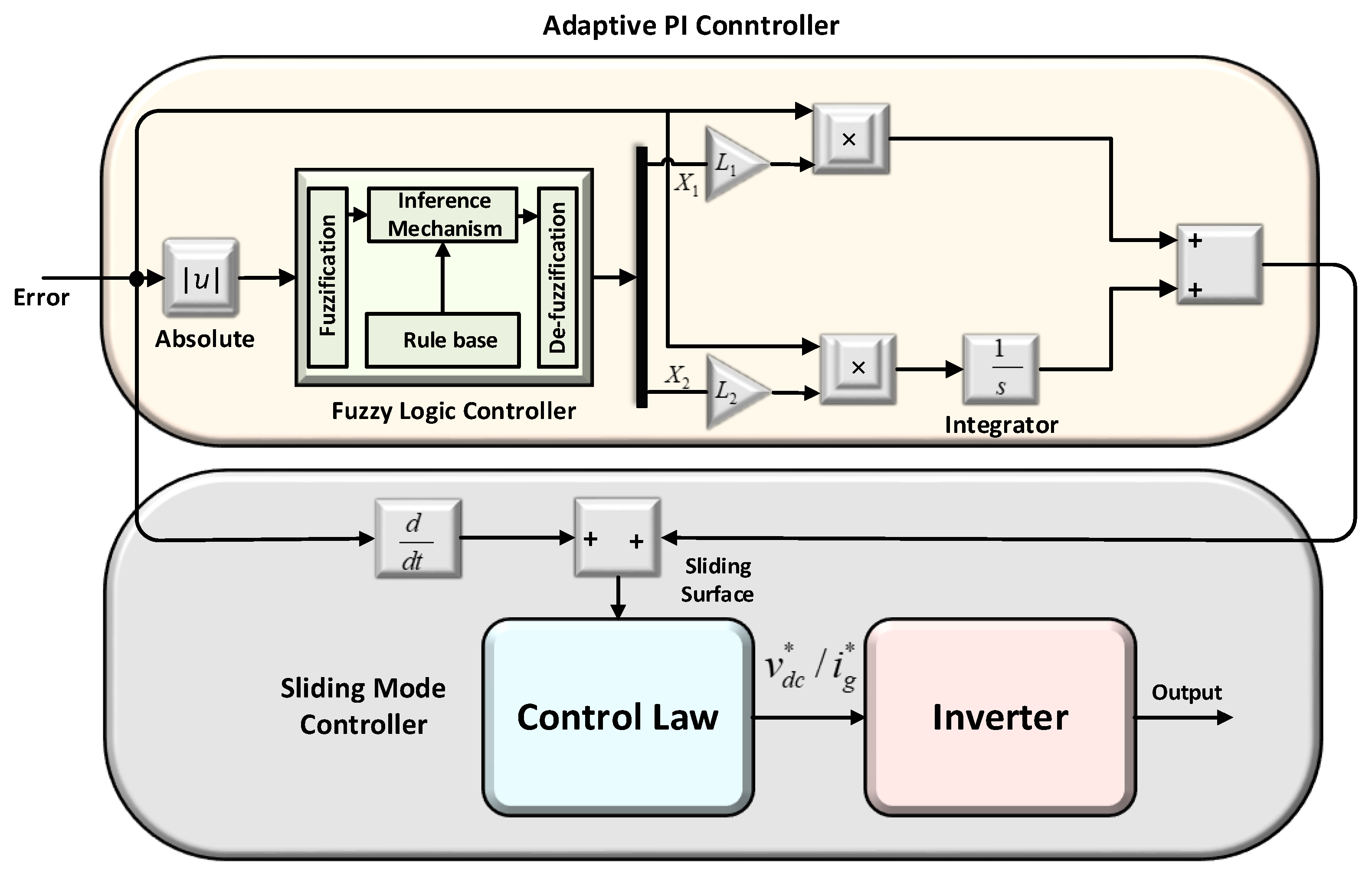
v D C * / i g * ( F u z z y ) = X 1 L 1 e ( t ) + X 2 L 2 e ( t ) d t .
where in Equation (10) X 1 and X 2 are the output of the Fuzzy controller and L 1 and L 2 are learning rate constants for k p and k i respectively, as shown in Figure 7.

4.2. Design of Fuzzy-Sliding Mode Controller

The structure of the Fuzzy-Sliding Mode Controller (F-SMC) or Adaptive Sliding Mode controller (ASMC) consists of two non-linear controllers, one of which is the Fuzzy-PI or Adaptive PI controller, and the other is the Sliding Mode Controller (SMC). The promising features of both these controllers are combined in F-SMC. The implementation of F-SMC is presented in Figure 8 [54]. The Fuzzy-PI is active in a steady state and reduces chattering in response. The gains of Fuzzy-PI, i.e., k p , and k i are updated using fuzzy IF-THEN rules [55,56]. The SMC is active during the transient state of the system, provides a fast-dynamic response and enhances system stability. Sliding Surface (SS) is calculated in the first step of SMC after that control law is designed that direct the controller to track the reference abruptly [57,58]. SS is calculated from error and the derivative of the error. In SMC, the error and derivative of error are always directed towards SS. The SS is defined:
S ( t ) = e ˙ ( t ) + λ e ( t )
In Equation (11), λ is an arbitrary constant whose values defends on bandwidth. Also, λ e ( t ) is calculated as:
λ e ( t ) = X 1 L 1 e ( t ) + X 2 L 2 e ( t )
The fuzzy-PI controller designed in the previous section is used to update λ e ( t ) . The discontinuous control law is designed in Equation (13) as:
v D C * / i g * = U s g n ( S ) .
where S is the sliding surface and U is tolerably large positive gain, and sgn function can be explained as:
s g n ( S ( t ) ) = { U i f S > 0 U i f S < 0 .
In electrical systems where PWM is employed, the control law designed in the above Equation causes oscillation and chattering phenomena. To avoid this, an alternate smooth control law is required. The “sgn” function is replaced by “sat”, which adds continuous smooth approximation to the system and defined below:
v D C * / i g * = U s a t ( σ ; ε ) = [ U S | S | + ε ] .      ε > 0           ε 0

5. Results and Discussion

The performance of the designed controllers and PLL being investigated and validated by various simulation results are discussed and described in case I and case II. A 3 kW two-stages single-phase grid-connected inverter structure with an LCL filter is designed. The platform used for implementation is MATLAB®/Simulink®/Simscape/PLECS. The specification of the system is given in Table 1. The specification of the PV panel is presented in Table A1, and the updated values of various controllers are given in Table A2 of the Appendix A. There are 15 PV modules in the string, and strings connected in parallel and are presented in Table A1. The essential purpose of simulations is twofold, i.e., (a) to verify the robustness of designed controllers, and (b) to compare the results with themselves and with a conventionally well-tuned PI controller.

5.1. Case I: Without Feedforward Loop of PV Power

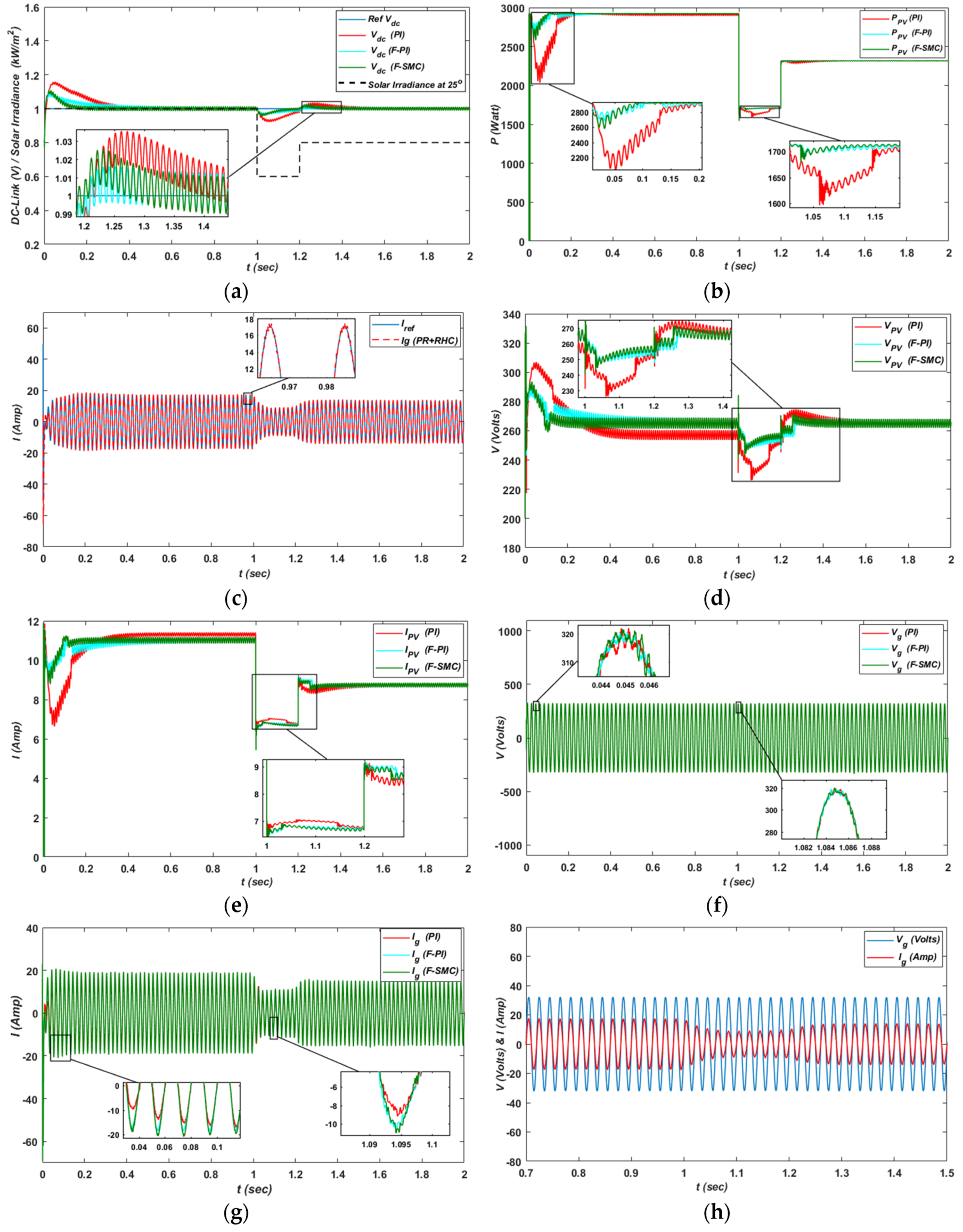
Case I explains the various results obtained without the feedforward loop of PV power for PI, F-PI, and F-SMC controllers. The control performance of each controller is tested by two analyses, i.e., graphical and tabulated. In the tabulated analysis, Integral Square Error (ISE), Integral Absolute Error (IAE), and Total Harmonic Distortion (THD) for grid voltage and grid current are calculated for both the DC-link loop and current controller loop. These parameters give the exact and precise comparison of the designed controllers. The lower the values in tabulated analysis, the better the efficiency. The design controllers give less value in comparison to the PI controller as presented in Table 3 for both the DC-link voltage and current control loop. The graphical analysis consists of various simulation results shown in Figure 9. Figure 9a presents the DC-link voltage of the designed controllers with the feedforward loop of PV power. The 400 DC-link voltage v d c is converted into 1 Per Unit (PU). At the start of the simulation, the PI controller shows a large overshoot of 0.15 PU that settles at 0.36 sec. The F-PI controller shows overshoot of 0.1 PU that settles at 0.3 sec. Similarly, the overshoot of F-SMC is 0.09 sec that settles abruptly at 0.18 sec. At 1 sec, the system is subjected to disturbance by changing solar irradiance from 1 kW/m2 to 0.6 kW/m2 and then to 0.8 kW/m2 at 1.2 sec. The PI controller shows sensitivity towards disturbance as compared to F-PI and F-SMC. Additionally, the PI controller overshoot and undershoot is high and the response is slower, comparatively.
Figure 9b presents the output power from the PV panels. The PI controller shows large variations in power compared to F-PI and F-SMC. At the start the power decrease to 2.1 kW from 3 kW, where the F-PI and F-SMC change to 2.6kW and 2.7 kW, respectively that abruptly reaches 3 kW. In addition, at 1 sec the solar irradiance varies that causes variation in the PI controller response. Furthermore, the response of the designed controller is faster, robust, less oscillatory, and improves the output power from the PV panel. The current loop response is presented in Figure 9c. This response is obtained using a proportional resonant controller with a harmonic compensator. Their values of the tuned controller are k p r = 22 , k p i = 2000 , k p i 3 = 1200 , k p i 5 = 800 , k p i 7 = 200 , respectively. This controller effectively removes the third, fifth, and sixth harmonics. The PV voltages and currents for each controller, i.e., PI, F-PI, and F-SMC are compared in Figure 9d,e, respectively. If we look at Figure 9d, especially the zoom window at 1 sec, the instantaneous panels output DC voltage shows overshoot for F-PI/F-SMC but that overshoot is extremely for short duration and its amplitude is 285 V, which is less compared to the starting overshoot amplitude, which is 305 V. Additionally, at this duration, the instantaneous panels output DC voltage does not stabilize and shows oscillatory behavior. Although the voltage at this point shows overshoot, the instantaneous panels output power shows negligible oscillation, comparative to PI. The instantaneous panels output DC current shows undershoot Figure 9e. The responses of grid voltages and grid currents for each controller, i.e., PI, F-PI, and F-SMC are compared in Figure 9f,g, respectively. Figure 9h shows the grid voltage and current which are in phase to effectively inject the inverter current into the grid. Besides, this figure confirms that the SOGI-based PLL has a fast-dynamic response, fast tracking accuracy, and harmonic immunity.

5.2. Case II: With Feedforward Loop of PV Power

In this case, the results of different parameters are considered for comparison of designed controllers, i.e., for PI, F-PI, PI, F-PI, and F-SMC controllers with a feedforward loop of PV power. First analysis for comparison is graphical while the second one is tabulated analysis. In the tabulated analysis, the performance of the DC-link loop and current control loop is tested on the basis of various parameters, i.e., ISE, IAE, and Total Harmonic Distortion (THD) for grid voltage and grid current as presented in Table 4. The lower these parameters, the better the performance of the controller. In comparison to Table 3, these values are minimum for PI, F-PI, and FSMC controllers, and this means the dynamics of the control loop are improved to a large extent. In addition, when self-comparison is carried out, the F-PI and F-SMC values are less when compared to the PI controller for both loops. Figure 10 presents the graphical comparison of the designed controllers. The response of the DC-link voltage for PI, F-PI, and F-SMC are presented in Figure 10a. The 1 PU is equivalent to 400 v d c . Initially, the spike in Vdc for the PI controller reaches to 1.081 PU and for F-PI and F-SMC approximately 1.06 PU. In addition, the PI controller settles at 0.35 sec while the F-PI and F-SMC approximately at 0.1 sec. At 1 sec, the system is subjected to disturbance by changing solar irradiance from 1 kW/m2 to 0.6 kW/m2 and 0.8 kW/m2 at 1.2 sec. The zoom area clearly demonstrations the sensitivity of PI controller towards the disturbance. The response of F-PI and F-SMC is faster, robust, with less oscillation, comparatively.
The PV panels power is presented in Figure 10b. In comparison to Figure 9b, the power is improved to a large extent. Initially, the PI controller power decrease/undershoot to approximately 2.7 kW whereas, F-PI to 2.83 kW and F-SMC to 2.9 kW. In addition, the zoom window at this interval shows large oscillation of the PI controller. Similarly, at 1 sec the solar irradiance varies from 1 kW/m2 to 0.6 kW/m2. The PI controller gives a large decrease in power compared to the F-PI and F-SMC, while the response of F-PI and F-SMC is almost similar. At 1.2 sec, the solar irradiance varies from 0.6 kW/m2 to 0.8 kW/m2 and the F-PI response is better while F-SMC shows a similar response to PI for 0.03 sec. Still, these responses are superior to without feedforward loop of PV power. Overall, the PI controller shows sensitivity to disturbances. Furthermore, the response of the designed controller is faster, reliable, less sensitive to disturbance, less oscillatory, and improves the output power from the PV panel. Figure 10c presents the response of the current loop. A proportional resonant controller with a harmonic compensator is used to perform efficiently and to remove the 3rd, 5th, and 7th harmonics. The zoom area in the figure shows effective tracking. The tuned values of this controller are presented in Table A2.
The PV voltages and currents for each controller, i.e., PI, F-PI, and F-SMC are compared in Figure 10d,e, respectively. If we look at Figure 10d, especially the zoom window at the start, the instantaneous panels output DC voltage shows less overshoot for F-PI/F-SMC. The response is better than that without the feedforward loop of the PV panel. After 1.2 s, the zoom window shows that the PI controller stabilizes slowly with oscillatory behavior. The response of F-SMC is similar to PI for some time, as shown in the second zoom window. Although the voltage at this point shows undershoot, the instantaneous panels output power shows negligible oscillation, comparative to the PI. The instantaneous panels output DC current shows overshoot in Figure 10e after 1.2 sec.
Additionally, in comparison to Figure 9d,e, these the current and voltage responses are improved and present less sensitivity towards disturbance in the form of solar irradiance. The responses of grid voltages and grid currents for each controller, i.e., PI, F-PI, and F-SMC, are compared in Figure 10f,g, respectively. The response for grid current and voltages improved by the implementation of the feedforward PV power loop. Besides, the zoom option shows that the PI controller has large spikes and oscillation comparatively to F-PI and F-SMC. Figure 10h shows the grid voltage and current that is in the phase to effectively inject the inverter current into the grid. It authenticates that the SOGI-based PLL employed in the system has a fast-dynamic response, fast-tracking accuracy, and harmonic immunity.

6. Conclusions

This paper successfully presented the design of a Fuzzy-Logic-Based PI (F-PI) and Fuzzy-Logic based Sliding Mode Controller (F-SMC) for a DC-link voltage controller and Proportional Resonant (PR) with Resonant Harmonic Compensator (RHC) as a current controller for a 3 kW Single-Phase Two-Stages Grid-Connected Transformerless (STGT) Photovoltaic (PV) Inverter. The current controller is tested and evaluated with and without a feedforward PV power loop. The feedforward loop improves the dynamics and control to a large extent. The SOGI PLL used has a fast-dynamic response, fast-tracking accuracy, and harmonic immunity. In comparison to PI, the designed controllers improve the steady-state and dynamic performance of the grid-connected PV system for DC-link voltage and current control loops. With the feedforward PV power loop, the DC-link voltage loop and current control loop guarantees globally stable, faster, and less sensitive to parameter variation response. The input power from the panels also improves in magnitude and has less oscillatory behavior. The quality of the grid current and voltage is also enhanced. In short, the results, performance measure analysis, and total harmonic distortion validate the robustness, fault tolerance, fastness, and effectiveness of the designed controllers, related to former works.
In the near future, the simulated results will be validated using hardware boards, e.g., DSPACE, FPGA, or TMS320F28335 DSP. Additionally, advanced controllers, i.e., Feedback Linearization control, High Order Adaptive SMC, H-infinity, Adaptive L1, and Fuzzy-Neural Network will be designed and compared with PI and themselves. In addition, to further enhance efficiency, Gallium Arsenide (GaN) and Silicon Carbide (SiC) switching devices will be used instead of MOSFET and IGBT.

Author Contributions

K.Z. proposed the main idea of the paper. K.Z. implemented the mathematical estimations, simulation verifications, and analyses. The paper was written by K.Z. and revised by S.U.I., W.U.D., I.K., M.I., T.D.C.B., I.A., and H.J.K. All the authors were involved in giving the final shape to this manuscript. Moreover, this work was supervised by H.J.K.

Acknowledgments

This Research was Supported by BK21PLUS, Creative Human Resource Development Program for IT Convergence.

Conflicts of Interest

The authors declare no conflict of interest.

Appendix A

Table A1. Specification of the PV panel used.
ParametersValues
Nominal power (1000 kW/m2, 25 °C) P m p p = 65 W
Short circuit current I S C = 3.99 A
Short circuit voltage V O C = 21.7 V
Current at MPPT I m p p = 3.69 A
Voltage at MPPT V m p p = 17.6 V
Table A2. Control Schemes Constants.
Control StrategiesParameterValues
Without feedforward loop of PV power
PI k p 32 × 400
k i 280 × 400
F-PI k 1 110
k 2 1080
F-SMC k 1 280
k 2 2980
ε 150
With feedforward loop of PV power
PI k p 32 × 400
k i 280 × 400
F-PI k 1 110
k 2 1080
F-SMC k 1 280
k 2 2980
ε 150
PR + RHC k p 22
k r 2000
k i 3 3rd harmonics compensation1200
k i 5 5th harmonics compensation800
k i 7 7th harmonics compensation200

References

  1. Sangwongwanich, A.; Yang, Y.; Blaabjerg, F.; Wang, H. Benchmarking of constant power generation strategies for single-phase grid-connected photovoltaic systems. IEEE Trans. Ind. Appl. 2018, 54, 447–457. [Google Scholar] [CrossRef]
  2. Zeb, K.; Uddin, W.; Khan, M.A.; Ali, Z.; Ali, M.U.; Christofides, N.; Kim, H.J. A Comprehensive Review on Inverter Topologies and Control Strategies for Grid Connected Photovoltaic System. Renew. Sustain. Energy Rev. 2018, 94, 1120–1141. [Google Scholar] [CrossRef]
  3. SolarPower Europe. Global Market Outlook for Solar Power 2015–2019. 2014. Available online: https: //helapco.gr/pdf/Global_Market_Outlook_2015_-2019_lr_v23.pdf (accessed on 24 July 2018).
  4. Zeb, K.; Khan, I.; Uddin, W. A Review on Recent Advances and Future Trends of Transformerless Inverter Structures for Single-Phase Grid-Connected Photovoltaic Systems. Energies 2018, 11, 1968. [Google Scholar] [CrossRef]
  5. Fraunhofer, I.S.E. Recent Facts about Photovoltaics in Germany. 19 May 2015. Available online: http://www.pv-fakten.de/ (accessed on 19 February 2019).
  6. Garnica Lopez, M.A.; Garcia de Vicuna, J.L.; Miret, J.; Castilla, M.; Guzmán, R. Control strategy for grid-connected three-phase inverters during voltage sags to meet grid codes and to maximize power delivery capability. IEEE Trans. Power Electron. 2018, 33, 9360–9374. [Google Scholar] [CrossRef]
  7. Islam, S.U.; Zeb, K.; Din, W.U.; Khan, I.; Ishfaq, M.; Hussain, A.; Busarello, T.D.C.; Kim, H.J. Design of Robust Fuzzy Logic Controller Based on the Levenberg Marquardt Algorithm and Fault Ride Trough Strategies for a Grid-Connected PV System. Electronics 2019, 8, 429. [Google Scholar] [CrossRef]
  8. Kouro, S.; Leon, J.I.; Vinnikov, D.; Franquelo, L.G. Grid-connected photovoltaic systems: An overview of recent research and emerging PV converter technology. IEEE Ind. Electron. Mag. 2015, 9, 47–61. [Google Scholar] [CrossRef]
  9. Bouzid, A.M.; Guerrero, J.M.; Cheriti, A.; Bouhamida, M.; Sicard, P.; Benghanem, M.A. Survey on control of electric power distributed generation systems for microgrid applications. Renew. Sustain. Energy Rev. 2015, 44, 751–766. [Google Scholar] [CrossRef]
  10. Eren, S.; Pahlevani, M.; Bakhshai, A.; Jain, P. An adaptive droop DC-bus voltage controller for a grid-connected voltage source inverter with LCL filter. IEEE Trans. Power Electron. 2015, 30, 547–560. [Google Scholar] [CrossRef]
  11. Raoufat, M.E.; Khayatian, A.; Mojallal, A. Performance Recovery of Voltage Source Converters with Application to Grid-Connected Fuel Cell DGs. IEEE Trans. Smart Grid 2018, 9, 1197–1204. [Google Scholar] [CrossRef]
  12. Ortega, M.; Hernández, J.; García, O. Measurement and assessment of power quality characteristics for photovoltaic systems: Harmonics, flicker, unbalance, and slow voltage variations. Electr. Power Syst. Res. 2013, 96, 23–35. [Google Scholar] [CrossRef]
  13. Barater, D.; Lorenzani, C.; Franceschini, G.; Franceschini, G.; Buticchi, G. Recent advances in single-phase transformerless photovoltaic inverters. IET Renew. Power Gener. 2016, 10, 260–273. [Google Scholar] [CrossRef]
  14. Medina, A.; Hernández, J.C.; Ortega, M.J.; Jurado, F. DC current injection into the network from transformerless and LF transformer photovoltaic inverters. In Proceedings of the 16th International Conference on Harmonics and Quality of Power (ICHQP), Bucharest, Romania, 25–28 May 2014; pp. 234–238. [Google Scholar]
  15. Yang, Y.; Zhou, K.; Wang, H.; Blaabjerg, F.; Wang, D.; Zhang, B. Frequency adaptive selective harmonic control for grid-connected inverters. IEEE Trans. Power Electron. 2015, 30, 3912–3924. [Google Scholar] [CrossRef]
  16. Rashed, M.; Klumpner, C.; Asher, G. Repetitive and resonant control for a single-phase grid-connected hybrid cascaded multilevel converter. IEEE Trans. Power Electron. 2013, 28, 2224–2234. [Google Scholar] [CrossRef]
  17. Xie, C.; Zhao, X.; Savaghebi, M.; Meng, L.; Guerrero, J.M.; Vasquez, J.C. Multirate fractional-order repetitive control of shunt active power filter suitable for microgrid applications. IEEE J. Emerg. Sel. Top. Power Electron. 2016, 5, 809–819. [Google Scholar] [CrossRef]
  18. Lidozzi, A.; Ji, C.; Solero, L.; Zanchetta, P.; Crescimbini, F. Resonantrepetitive combined control for stand-alone power supply units. IEEE Trans. Ind. Appl. 2015, 51, 4653–4663. [Google Scholar] [CrossRef]
  19. Liu, T.; Wang, D.; Zhou, K. High-performance grid simulator using parallel structure fractional repetitive control. IEEE Trans. Power Electron. 2016, 31, 2669–2679. [Google Scholar] [CrossRef]
  20. Kumar, N.; Saha, T.K.; Dey, J. Sliding-mode control of PWM dual inverter based grid-connected PV system: Modeling and performance analysis. IEEE J. Emerg. Sel. Top. Power Electron. 2016, 4, 435–444. [Google Scholar] [CrossRef]
  21. Shen, G.; Zhu, X.; Zhang, J.; Xu, D. A new feedback method for PR current control of LCL-filter-based grid-connected inverter. IEEE Trans. Ind. Electron. 2010, 57, 2033–2041. [Google Scholar] [CrossRef]
  22. Khajehoddin, S.A.; Karimi-Ghartemani, M.; Jain, P.K.; Bakhshai, A. A resonant controller with high structural robustness for fixed-point digital implementations. IEEE Trans. Power Electron. 2012, 27, 3352–3362. [Google Scholar] [CrossRef]
  23. Jinwei, H.; Yun, L.W.; Munir, M.S. A flexible harmonic control approach through voltage-controlled DG–Grid interfacing converters. IEEE Trans. Ind. Electron. 2012, 59, 444–455. [Google Scholar]
  24. Yepes, A.G.; Freijedo, F.D.; Lopez, O.; Doval-Gandoy, J. High performance digital resonant controllers implemented with two integrators. IEEE Trans. Power Electron. 2011, 26, 563–576. [Google Scholar] [CrossRef]
  25. Davoodnezhad, R.; Holmes, D.G.; McGrath, B.P. A fully digital hysteresis current controller for current regulation of grid connected pv inverters. In Proceedings of the 2014 IEEE 5th International Symposium on Power Electronics for Distributed Generation Systems (PEDG), Galway, Ireland, 24–27 June 2014; pp. 1–8. [Google Scholar]
  26. Wu, F.; Sun, B.; Zhao, K.; Sun, L. Analysis and solution of current zero crossing distortion with unipolar hysteresis current control in grid-connected inverter. IEEE Trans. Ind. Electron. 2013, 60, 4450–4457. [Google Scholar] [CrossRef]
  27. Fuchs, F.; Dannehl, J.; Fuchs, F.W. Discrete sliding mode current control of grid-connected three-phase PWM converters with LCL filter. In Proceedings of the 2010 IEEE International Symposium on Industrial Electronics, Bari, Italy, 4–7 July 2010; pp. 779–785. [Google Scholar]
  28. Hao, X.; Yang, X.; Liu, T.; Huang, L.; Chen, W. A sliding-mode controller with multi resonant sliding surface for single-phase grid-connected VSI with an LCL filter. IEEE Trans. Power Electron. 2013, 28, 2259–2268. [Google Scholar] [CrossRef]
  29. Ho, C.N.M.; Cheung, V.S.P.; Chung, H.S.H. Constant-frequency hysteresis current control of grid-connected VSI without bandwidth control. IEEE Trans. Power Electron. 2009, 24, 2484–2495. [Google Scholar] [CrossRef]
  30. Ahmed, T.; Nishida, K.; Nakaoka, M. Deadbeat current control of LCL-filter for grid connected three-phase voltage source inverter. In Proceedings of the 2011 IEEE Ninth International Conference on Power Electronics and Drive Systems (PEDS), Singapore, 5–8 December 2011; pp. 459–467. [Google Scholar]
  31. Altin, N.; Sefa, I. dSPACE based adaptive neuro-fuzzy controller of grid interactive inverter. Energy Convers. Manag. 2012, 56, 130–139. [Google Scholar] [CrossRef]
  32. Sefa, I.; Altin, N.; Ozdemir, S.; Kaplan, O. Fuzzy PI controlled inverter for grid interactive renewable energy systems. IET Renew. Power Gener. 2015, 9, 729–738. [Google Scholar] [CrossRef]
  33. Cespedes, M.; Sun, J. Adaptive control of grid-connected inverters based on online grid impedance measurements. IEEE Trans. Sustain. Energy 2014, 5, 516–523. [Google Scholar] [CrossRef]
  34. Fu, X.; Li, S. Control of single-phase grid-connected converters with LCL filters using recurrent neural network and conventional control methods. IEEE Trans. Power Electron. 2016, 31, 5354–5364. [Google Scholar] [CrossRef]
  35. Blaabjerg, F.; Ionel, D.M. Renewable Energy Devices and Systems with Simulations in MATLAB and ANSYS; Taylor & Francis: Boca Raton, FL, USA, 2017. [Google Scholar]
  36. Bae, Y.; Vu, T.-K.; Kim, R.-Y. Implemental control strategy for grid stabilization of grid-connected PV system based on German grid code in symmetrical low-to-medium voltage network. IEEE Trans. Energy Convers. 2013, 28, 619–631. [Google Scholar] [CrossRef]
  37. Dutta, S.; Debnath, D.; Chatterjee, K. A grid-connected single-phase transformerless inverter controlling two solar PV arrays operating under different atmospheric conditions. IEEE Trans. Ind. Electron. 2018, 65, 374–385. [Google Scholar] [CrossRef]
  38. Femia, N.; Petrone, G.; Spagnuolo, G.; Vitelli, M. Optimization of perturb and observe maximum power point tracking method. IEEE Trans. Power Electron. 2005, 20, 963–973. [Google Scholar] [CrossRef]
  39. Sera, D.; Mathe, L.; Blaabjerg, F. Distributed control of PV strings with module integrated converters in presence of a central MPPT. In Proceedings of the 2014 IEEE Energy Conversion Congress and Exposition (ECCE), Pittsburgh, PA, USA, 14–18 September 2014; pp. 1–8. [Google Scholar]
  40. Maris, T.I.; Kourtesi, S.; Ekonomou, L.; Fotis, G.P. Modeling of a single-phase photovoltaic inverter. Sol. Energy Mater. Sol. Cells 2007, 91, 1713–1725. [Google Scholar] [CrossRef]
  41. Islam, S.U.; Zeb, K.; Din, W.U.; Khan, I.; Ishfaq, M.; Busarello, T.D.C.; Kim, H.J. Design of a Proportional Resonant Controller with Resonant Harmonic Compensator and Fault Ride Trough Strategies for a Grid-Connected Photovoltaic System. Electronics 2018, 7, 451. [Google Scholar] [CrossRef]
  42. Yang, Y.; Blaabjerg, F.; Wang, H. Low voltage ride-through of single-phase transformerless photovoltaic inverters. IEEE Trans. Ind. Appl. 2014, 50, 1942–1952. [Google Scholar] [CrossRef]
  43. Yang, Y.; Blaabjerg, F.; Wang, H.; Simões, M.G. Power control flexibilities for grid-connected multi-functional photovoltaic inverters. IET Renew. Power Gener. 2016, 10, 504–513. [Google Scholar] [CrossRef]
  44. Teodorescu, R.; Liserre, M.; Rodriguez, P. Grid Converters for Photovoltaic and Wind Power Systems; Wiley: Hoboken, NJ, USA, 2011. [Google Scholar]
  45. Yang, Y.; Hadjidemetriou, L.; Blaabjerg, F.; Kyriakides, E. Benchmarking of phase locked loop-based synchronization techniques for grid-connected inverter systems. In Proceedings of the 2015 9th International Conference on Power Electronics and ECCE Asia (ICPE-ECCE Asia), Seoul, Korea, 1–5 June 2015; pp. 2167–2174. [Google Scholar]
  46. Fengjiang, W.; Lujie, Z.; Jiandong, D. A New Two-Phase Stationary Frame-Based Enhanced PLL for Three-Phase Grid Synchronization. IEEE Trans. Circuits Syst. II Express Briefs 2015, 62, 251–255. [Google Scholar]
  47. Ciobotaru, M.; Teodorescu, R.; Blaabjerg, F. A new single-phase PLL structure based on second order generalized integrator. In Proceedings of the 2006 37th IEEE Power Electronics Specialists Conference, Jeju, Korea, 18–22 June 2006; pp. 1–6. [Google Scholar]
  48. Yang, Y.; Blaabjerg, F. Synchronization in single-phase grid connected photovoltaic systems under grid faults. In Proceedings of the 2012 3rd IEEE International Symposium on Power Electronics for Distributed Generation Systems (PEDG), Aalborg, Denmark, 25–28 June 2012; pp. 476–482. [Google Scholar]
  49. Yang, Y.; Blaabjerg, F.; Zou, Z. Benchmarking of grid fault modes in single-phase grid-connected photovoltaic systems. IEEE Trans. Ind. Appl. 2013, 49, 2167–2176. [Google Scholar] [CrossRef]
  50. Xiao, F.; Dong, L.; Li, L.; Liao, X. A frequency-fixed SOGI-based PLL for single-phase grid-connected converters. IEEE Trans. Power Electron. 2017, 32, 1713–1719. [Google Scholar] [CrossRef]
  51. Ishfaq, M.; Uddin, W.; Zeb, K.; Khan, I.; Ul Islam, S.; Adil Khan, M.; Kim, H.J. A New Adaptive Approach to Control Circulating and Output Current of Modular Multilevel Converter. Energies 2019, 12, 1118. [Google Scholar] [CrossRef]
  52. Khan, I.; Zeb, K.; Din, W.U.; Islam, S.U.; Ishfaq, M.; Hussain, S.; Kim, H.-J. Dynamic Modeling and Robust Controllers Design for Doubly Fed Induction Generator-Based Wind Turbines under Unbalanced Grid Fault Conditions. Energies 2019, 12, 454. [Google Scholar] [CrossRef]
  53. Hannan, M.A.; Ali, J.A.; Mohamed, A.; Amirulddin, U.A.U.; Tan, N.M.L.; Uddin, M.N. Quantum-Behaved Lightning Search Algorithm to Improve Indirect Field-Oriented Fuzzy-PI Control for IM Drive. IEEE Trans. Ind. Appl. 2018, 54, 3793–3805. [Google Scholar] [CrossRef]
  54. Zeb, K.; Ayesha; Haider, A.; Uddin, W.; Qureshi, M.B.; Mehmood, C.A.; Jazlan, A.; Sreeram, V. Indirect Vector Control of Induction Motor using Adaptive Sliding Mode Controller. In Proceedings of the IEEE Australian Control Conference (AUCC), Newcastle, NSW, Australia, 3–4 November 2016; pp. 358–363. [Google Scholar]
  55. Zeb, K.; Ali, Z.; Saleem, K.; Uddin, W.; Javed, M.A.; Christofides, N. Indirect Field-Oriented Control of Induction Motor Drive based on Adaptive Fuzzy Logic Control. Electr. Eng. 2017, 99, 803–815. [Google Scholar] [CrossRef]
  56. Zeb, K.; Din, W.U.; Khan, M.A.; Khan, A.; Younas, U.; Busarello, T.D.C.; Kim, H.J. Dynamic Simulations of Adaptive Design Approaches to Control the Speed of an Induction Machine Considering Parameter Uncertainties and External Perturbations. Energies 2018, 11, 2339. [Google Scholar] [CrossRef]
  57. Saghafinia, A.; Ping, H.W.; Uddin, M.N.; Gaeid, K.S. Adaptive Fuzzy Sliding Mode Control into Chattering Free IM Drive. IEEE Trans. Ind. Appl. 2015, 51, 692–702. [Google Scholar] [CrossRef]
  58. El-Sousy, F.F.M. Adaptive Dynamic Sliding-Mode Control System Using Recurrent RBFN for High-Performance Induction Motor Servo Drive. IEEE Trans. Ind. Inform. 2013, 9, 1922–1936. [Google Scholar] [CrossRef]
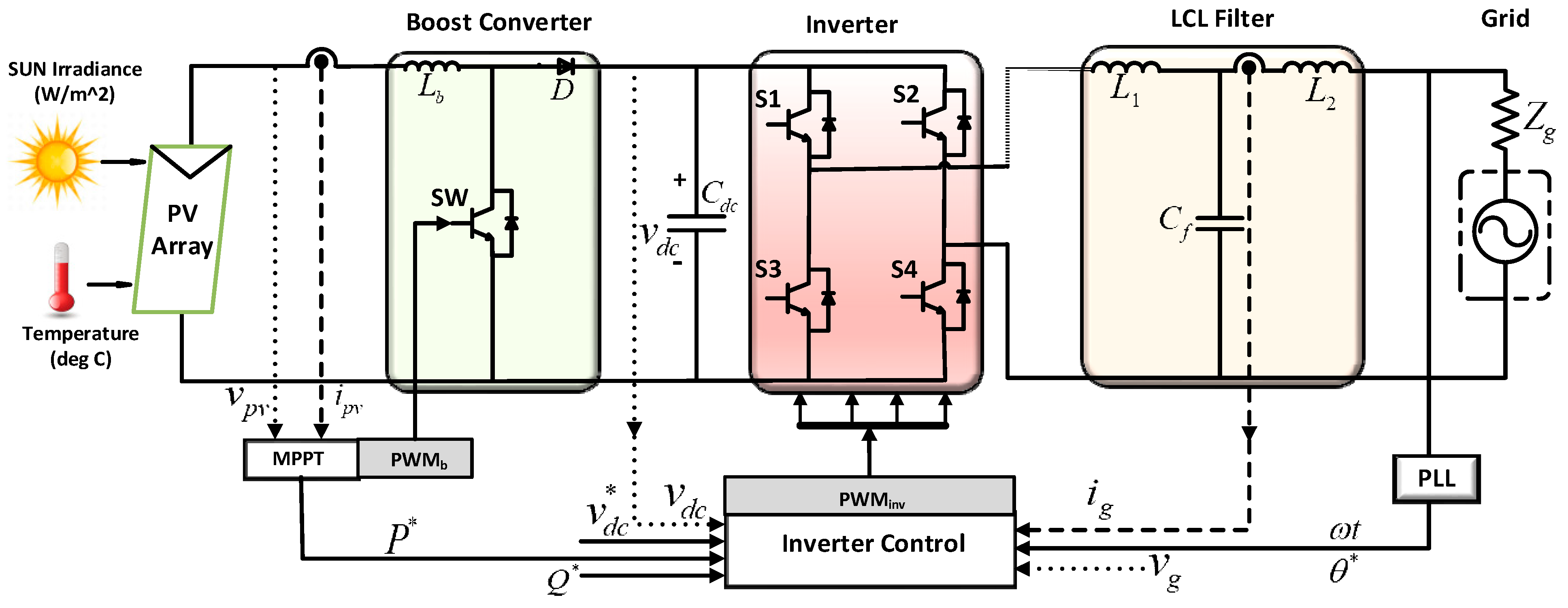
Figure 1. A two-stage single phase grid-connected PV system with an LCL filter.
Electronics 08 00520 g001
Figure 2. The Perturb and Observe algorithm-based MPPT control structure for the boost converter.
Electronics 08 00520 g002
Figure 3. The proportional resonant controller with the resonant harmonic compensator.
Electronics 08 00520 g003
Figure 4. The proportional control loop (a) with and (b) without feed-forward PV power, respectively.
Electronics 08 00520 g004
Figure 5. Structure of the Second Order Generalized Integrator (SOGI) PLL.
Electronics 08 00520 g005
Figure 6. Fuzzy Controller Architecture.
Electronics 08 00520 g006
Figure 7. Fuzzy-PI controller.
Electronics 08 00520 g007
Figure 8. The Fuzzy-Sliding Mode Controller.
Electronics 08 00520 g008
Figure 9. (a) DC-link voltage and SI using PI, F-PI, and F-SMC; (b). PV panels power using PI, F-PI, and F-SMC; (c) proportional resonant controller with RHC for the current loop; (d) PV panels voltages using PI, F-PI, and F-SMC; (e) PV panels currents using PI, F-PI, and F-SMC; (f) grid voltages using PI, F-PI, and F-SMC; (g) grid currents using PI, F-PI, and F-SMC; (h) response of the grid voltage and grid current.
Electronics 08 00520 g009
Figure 10. (a) DC-link voltage and SI using PI, F-PI, and F-SMC; (b) PV panels power using PI, F-PI, and F-SMC; (c) the proportional resonant controller with RHC for current loop; (d) PV panels voltages using PI, F-PI, and F-SMC; (e) PV panels currents using PI, F-PI, and F-SMC; (f) grid voltages using PI, F-PI, and F-SMC; (g) grid currents using PI, F-PI, and F-SMC; (h) response of grid voltage and grid current.
Electronics 08 00520 g010
Table 1. Rated parameters of the 3 kW grid-connected photovoltaic model.
ParametersSymbolsValues
Grid voltage (RMS) V g 230 V
Grid Operating Frequency ω g 314 rad/sec
Boost-converter switching frequency f b 20 kHz
Boost Inductance L b 2 m H
Grid- impedance L g , R g 0.5 m H , 0.2 Ω
Reference DC-link voltage V d c * 400 V
DC-link voltage capacitance C D C 2200 μ F
LCL-Filter L 1 , C f , L 2 1.8 mH, 2.35 µF, 1.8 mH
Switching Frequency of Inverter f i n v 10 kHz
Table 2. IF-THEN rules for Fuzzy-PI and F-SMC.
Input Membership Function Output Membership FunctionIF-THEN Rules
S. No.Linguistic TermsRangeLinguistic TermsRangeIF Input | e ( t ) | THEN output ( k p , k i )
1Zero[0, 0.2]Zero[0, 0.2]ZeroZero
2Small[0.3, 0.7]Small[0.3, 0.7]SmallSmall
3Large[0.8, 1.0]Large[0.8, 1.0]LargeLarge
Table 3. Performance of the designed controllers without the feed-forward loop of PV power.
Controllers DesignedDC-LinkCurrent ControllerTotal Harmonic Distortion
ISEIAEISEIAE V g I g
PI0.0033710.048154.2021.03054.89706.8970
F-PI0.0009150.027613.6980.71652.62302.1940
F-SMC0.0007690.023163.3080.89363.09801.5560
Table 4. Performance of the designed controllers with feed-forward loop of PV power.
Controllers DesignedDC-LinkCurrent ControllerTotal Harmonic Distortion
ISEIAEISEIAE V g I g
PI0.0004450.019233.45701.033010.5703.3882
F-PI0.0002930.015742.63400.71613.19801.5520
F-SMC0.0002320.013602.59400.871092.99101.4521