1. Introduction
The central characteristic of Industry 4.0 is the convergence of information and communication technologies. Industry 4.0 combines new technological innovation in six fields: Big Data Analysis, Artificial Intelligence, Robotics, Internet of Things, Unmanned Transportation, 3D Printing, and Nanotechnology [
1]. This industry 4.0 utilizes a large number of digital data, including personal information. In addition, a large number of data are created from personal information, from who we are, where we have been, and where we plan to go, to bank details and heart rate [
2]. As a result, the number of large-scale data centers is increasing rapidly around the world, and interest in energy consumption of data centers is increasing [
3]. These data centers account for more than 1% of global electricity usage. They consist of IT facilities, power systems, cooling and ventilation systems. Among these components, IT equipment consumes from 30% to 50% of total energy, and cooling and ventilation systems consume ~40% of total energy [
4]. In order to reduce energy consumption, it is necessary to control the flow of the bottom air efficiently. In order to reduce power consumed in the data center, Google has used AI control, resulting in a reduction in energy consumption of ~40% [
5].
Temperature management of electronic devices constituting these data centers is very important, and problems arising during the operation of electrical equipment are mostly caused by temperature [
6]. Methods for managing the temperature include air cooling, liquid cooling, heat pipes, refrigeration cooling, thermoelectric cooling, and phase change material-based cooling methods. Of these, air cooling and liquid cooling are the simplest and most commonly used methods. Cooling methods applied to the data center include air-based cooling and liquid-based cooling. The air-based cooling method cools the IT equipment with cooled air passing into the equipment, and the efficiency and performance change depending on the method of construction. Water is widely used to cool all types of mechanical and industrial systems, but the risks associated with leakage are too high to be used directly to cool data center servers, and special equipment and solutions are needed [
6,
7].
The air-based cooling method can improve cooling efficiency by forcibly circulating heated air, and the liquid-based cooling method can also improve the cooling efficiency by forcibly lowering the temperature of the heated liquid. In general, a fan is used to circulate air and lower the temperature of the heated liquid. Depending on the performance of the fan, the cooling performance can be influenced.
A thermoelectric device is a device that converts electrical energy into thermal energy and thermal energy into electrical energy. In particular, due to its ability to generate electrical energy using heat, thermoelectric devices are environmentally friendly devices and have advantages in minimizing global warming and environmental pollution. In addition, the thermoelectric element can convert electric energy into heat energy and can be used as a heat source for cooling and heating. This feature allows it to be used in various applications ranging from producing electricity from the waste heat of automobiles to small applications like computers [
8,
9,
10].
Cooling systems using thermoelectric elements include refrigerators using thermoelectric elements [
11,
12,
13,
14,
15,
16,
17,
18], electronic equipment coolers [
19,
20,
21,
22,
23,
24,
25,
26,
27], dehumidifiers [
28,
29], and air conditioners [
30]. In air conditioners in particular the performance of a hybrid system which combines the thermoelectric elements is 10% higher than conventional systems. As such, thermoelectric devices are used in a variety of temperature management applications.
Cooling using these thermoelectric elements can be presented as a unique solution to the problem of keeping the temperature lower than the indoor temperature and has many advantages as follows.
It does not need any maintenance because there is no driving part.
It is smaller and lighter than existing cooling systems and can be applied to various applications in various standard sizes.
Both heating and cooling can be selected according to the polarity of the supplied DC power supply.
Closed loop temperature control allows accurate temperature control over +/− 0.1 °C.
The thermoelectric device has high reliability due to the solid state structure, and the lifetime of the thermoelectric device in general is over 200,000 hours.
Since there is no driving part, it is noiseless and can be used with sensitive sensors.
Thermoelectric devices are powered by DC power, so modules with wide input voltage and current can be used. Pulse width modulation (PWM) can be applied to various applications.
It can be cooled to a lower temperature than the indoor temperature.
Using the temperature difference of the thermoelectric elements, DC power can be produced.
Conventional refrigeration systems use chlorofluorocarbons or other chemicals that can be harmful to the environment, but thermoelectric devices do not use or produce any kind of gas.
A thermoelectric element is a device in which heat absorption and generation occur simultaneously when DC power is input. When the thermoelectric element is cooled using the heat absorbing side of the thermoelectric element, heat is generated on the opposite side. Such a thermoelectric element generally has a structure for attaching a heat sink, and the cooling performance of the heat sink is greatly influenced by the thermal resistance of the selected heat sink. Therefore, it is very important to select a heat sink suitable for a cooling system when using a thermoelectric device for cooling [
31,
32]. The performance of the thermoelectric element can be expressed by COP (coefficient of performance), with COP representing the ratio of the amount of heat absorbed to the power input to the thermoelectric element. This ratio increases as the temperature difference between the heat absorbing side and the heat generating side of the thermoelectric element decreases, and the COP becomes very low when the temperature difference becomes larger. Therefore, efficient cooling of the heat generating side is essential for high COP [
33].
Fuzzy control has been used to describe uncertain systems since it was first discovered by Professor Zadeh. Fuzzy control is used for the control of many industrial systems and has the advantage that it can be applied without accurate modeling [
34,
35,
36,
37,
38]. The PI controller is the most widely used controller in the industrial field and has the advantage that the structure is simple, and thus the relationship between the gain and the control value is clear. However, the PI control has a limitation in satisfying both the transient state and the steady state due to the fixed gain value. In particular, there is a problem wherein a cumulative error occurs due to the integral operation. In order to solve this problem, a control scheme that automatically adjusts the gain of the PI controller has been researched. However, since the proportional gain and the integral gain are continuously calculated according to the operation state, the calculation amount increases and a high-performance CPU is necessary for fast processing. Therefore, in this paper, we propose a new control scheme consisting of a fuzzy controller and PI controller to solve these problems.
In this paper, we propose an FPI controller that controls the input value of the PI controller using fuzzy control, a VFPI controller that adjusts the fuzzy control gain of the FPI controller, and a variable fuzzy proportion integration-variable limit (VFPI-VL) controller that adjusts the output limit of the VFPI controller. The limitation of the performance improvement by the fixed gain value of the conventional PI controller can be solved by adjusting the input value using the fuzzy control and the control performance can be improved by adjusting the gain value of the fuzzy control and the limit value of the controller output. The control method proposed in this paper is applied to the control system using fan. The cooling system using the fan changes the power consumption according to the operating time and speed of the fan. The method proposed in this paper optimally controls the operation time and speed of the fan according to the operating conditions, thereby reducing the power consumption of the fan. The controller proposed in this paper can be applied to various variable speed drive systems, and it is expected to improve speed control performance and reduce power consumption.
This paper is organized as follows. In
Section 2, the characteristics of thermoelectric devices are introduced.
Section 3 shows the cooling system using a thermoelectric device. In
Section 4, a new control method combining a fuzzy controller and PI controller is proposed.
Section 5 shows the experimental results of the method proposed in this paper and the validity of said results are analyzed. Finally,
Section 6 presents the conclusion and future work suggested by this paper.
2. Characteristics of Thermoelectric Device
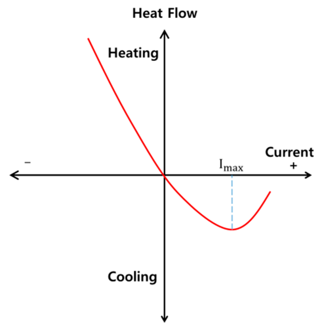
The thermoelectric element is a semiconductor element that utilizes the Peltier effect. The Peltier effect is a phenomenon in which the heat absorption and heat generation appear according to the direction of the direct current as shown in
Figure 1. It can be changed from cooling to heating by changing the direction of the current without mechanical change.
These thermoelectric elements can maintain a temperature difference of up to ~70 °C. Such a thermoelectric device has the advantage that the affected area can be cooled to a temperature much lower than the ambient temperature, and it is possible to maintain the state of ± 0.01 °C even in a normal state [
32].
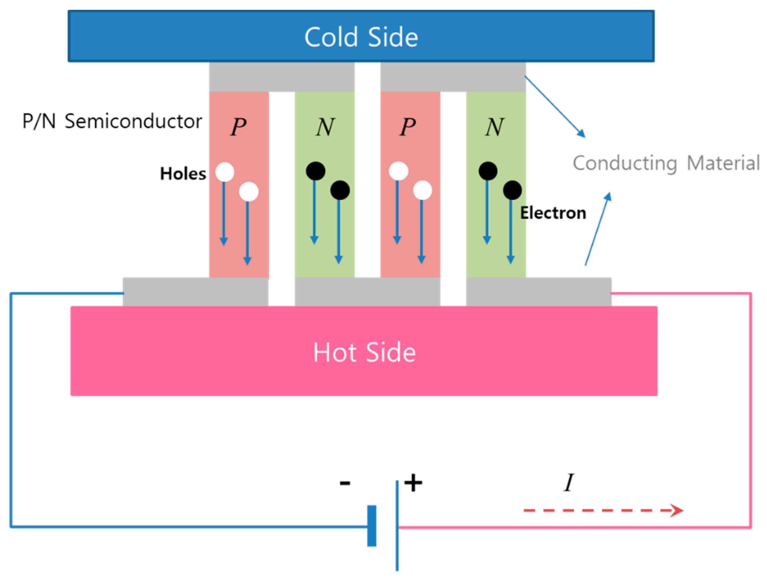
Figure 2 shows the structure of the thermoelectric element [
29].
The most important parameter in a cooling system using a thermoelectric element is the coefficient of performance (COP:
). The COP (
) can be calculated as shown in Equation (1).
where
is the amount of heat absorbed on the cold side and P is the input power. The heat absorbed amount (
) is the sum of heat due to the Peltier effect, Joule heat, and heat conduction. The
can be calculated as shown in Equation (2).
where,
,
,
is the Seebeck coefficient of P and N type semiconductor (
),
is the current(
), R is the electric resistance(
), and K is coefficient of thermal coefficient (
), respectively.
(
) is the temperature difference between the cold side and the hot side of thermoelectric device (°C),
is the hot side temperature (°C), and
is the cold side temperature (°C).
The current can be expressed as Equation (3) using the voltage generated by the Seebeck effect and the supply voltage. The input power P is the sum of the power and the joule heat generated by the Seebeck effect and can be expressed as Equation (4) [
39,
40].
3. Cooling System using Thermoelectric Device
When a thermoelectric device is used for cooling in
Figure 1, when a current higher than the maximum current (I
max) is supplied, the temperature rises again due to the internal power loss (
). Therefore, care should be taken not to exceed the maximum current when using thermoelectric elements. Cooling using a thermoelectric element can cause the temperature to drop lower than the surrounding temperature, and has the advantage of precise temperature control. In addition, it can go from cooling to heating by changing the direction of the current without mechanical changes. In cooling using the thermoelectric device, when the supplied current to the thermoelectric device is more than maximum current (I
max), there is a problem wherein the power loss consumed in the thermoelectric element increases and the temperature rises again. Therefore, care should be taken so that the supplied current does not exceed the maximum current (I
max).
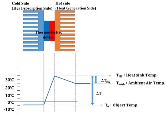
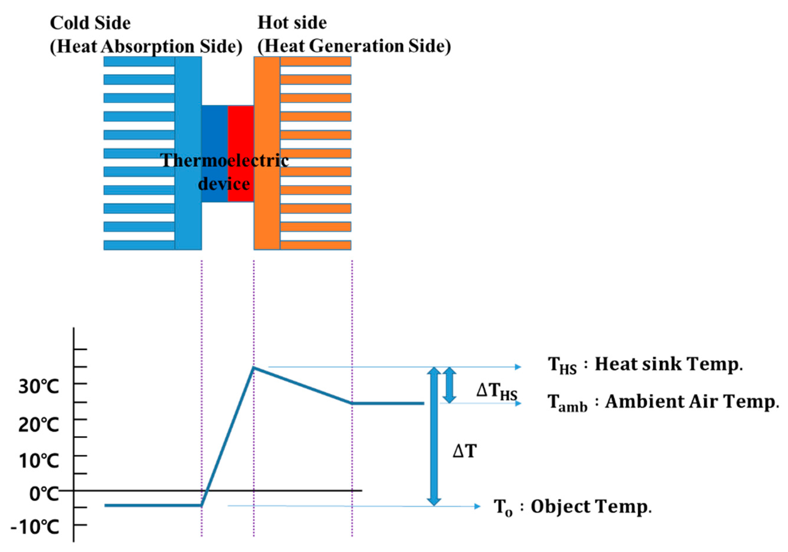
Figure 3 shows a cooling system using a thermoelectric element. The object temperature (
) represents the temperature required for cooling and is the temperature of the heat absorbing side (Cold Side) of the thermoelectric element. The heat sink temperature (
) represents the temperature of the heat sink attached to the heat generation side (Hot Side) of the thermoelectric element.
is the difference in temperature between
and
.
represents the ambient air temperature. The maximum value of
has a limit value for every thermoelectric device. When the temperature of the ambient air is constantly maintained,
must be lowered in order to lower
.
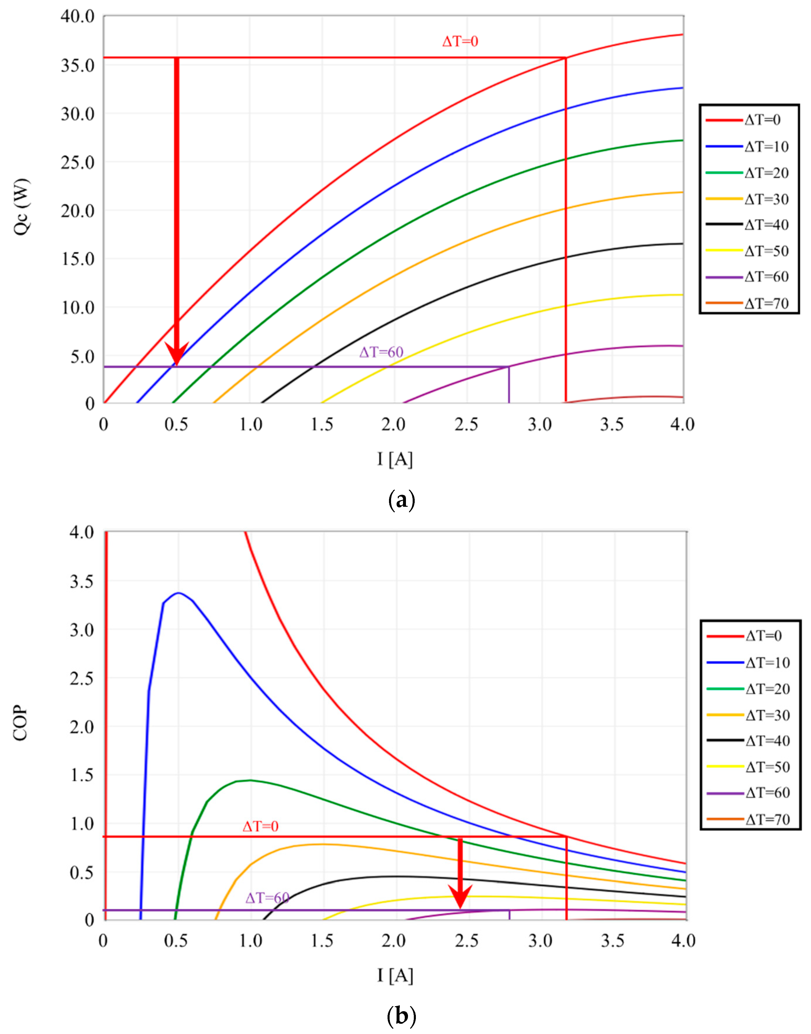
Figure 4 shows the characteristics of the thermoelectric element 9501/127/040 B model [
41]. The maximum current (I
max) of this model is 4A, the maximum voltage (V
max) is 17.5V, the maximum temperature difference ΔT is 72 °C, and the maximum heat absorbing amount (
) is 38W.
Figure 4a shows the comparison of the heat absorption amount (
) according to the current and the temperature difference and
Figure 4b shows the comparison of the COP (coefficient of performance) according to the current and the temperature difference. As shown in
Figure 4, when the temperature difference (ΔT) increases, the heat absorption and COP decrease. Therefore, in order to improve the cooling performance of the cooling system using the thermoelectric element, the temperature difference between the high temperature surface and the low temperature surface of the thermoelectric element must be reduced. For this purpose, high temperature surface cooling performance is very important.
4. Proposed Control Method
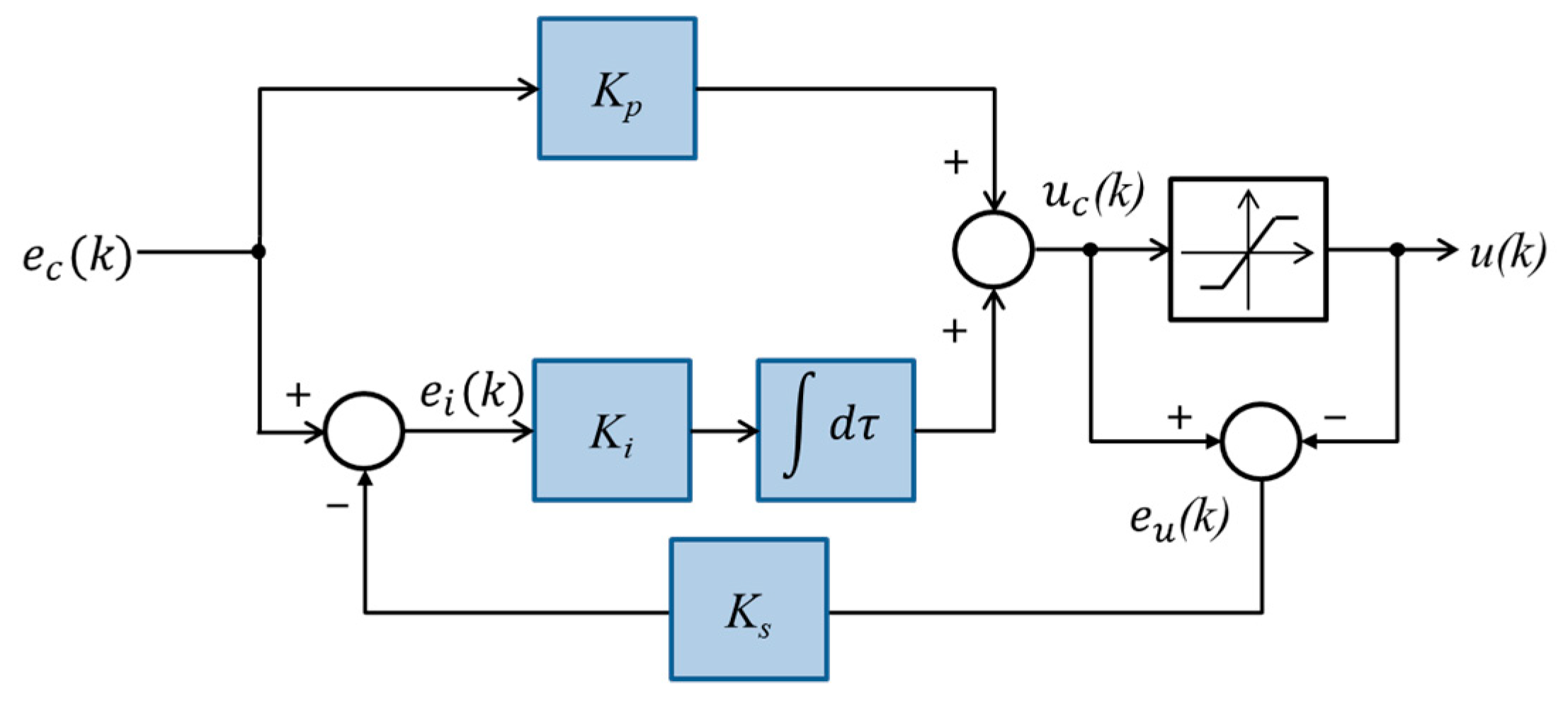
The PI controller is the most widely used controller in the industrial field. The PI controller performs control using two gain values (proportional gain and integral gain), and the rise time, overshoot, stabilization time, and qualitative state error are changed according to these gain values. There are various methods to set the gain of the PI controller, but we use a lot of trial and error methods that do not require mathematical knowledge and can be controlled in real time. The integral operation of the PI control causes the problem of saturating the control value due to an error occurring in the steady state, thereby causing the problem of delaying the control in the next transient state. This problem is called the wind-up phenomenon, and the way to prevent it is called anti-wind-up. In this paper, we use the method depicted in
Figure 5 for anti-wind-up. In
Figure 5,
is before the limit, and
is the PI controller output after the limit. The error value (
) between these two values is calculated by Equation (7). If this value (
) is generated, it can be determined that the saturation of the output value of the PI controller has occurred. Since the saturation phenomenon of the output value of the PI controller is generated by the integral control, the input value of the integral control is reduced by the Equation (8) using the output value error (
), as the result the integral output is adjusted. The control amount of PI controller is given by Equation (11) and the change of control amount (
) can be expressed as Equation (13) by using the current output
and previous output
.
In order to solve the disadvantages of PI controller with fixed gain, methods of adjusting gain value have been proposed [
42,
43,
44]. The PI controller uses the proportional gain and the integral gain. In order to automatically adjust the gain value, the PI controller has to calculate the two values according to the operation state, which increases the calculation time. To solve this problem, a high-performance CPU is required. Therefore, in this paper, we propose a method to adjust the input value of PI controller to solve the problem of fixed gain of PI controller. When the input value is adjusted, only one controller is used. Therefore, the calculation time is faster than the method of adjusting the gain value.
In this paper, a fuzzy controller is used to improve the performance of the PI controller. Fuzzy control is a system that does not require mathematical modeling and is robust in dealing with transient conditions. The rule base in
Table 1 represents 49 rules that are commonly used in fuzzy control. The rule base in
Table 1 is used for temperature control, PWM control of inverter for wind power generation, and fuzzy control for controlling gain of proportional integral differential (PID) controller, as well as motor speed control [
45,
46,
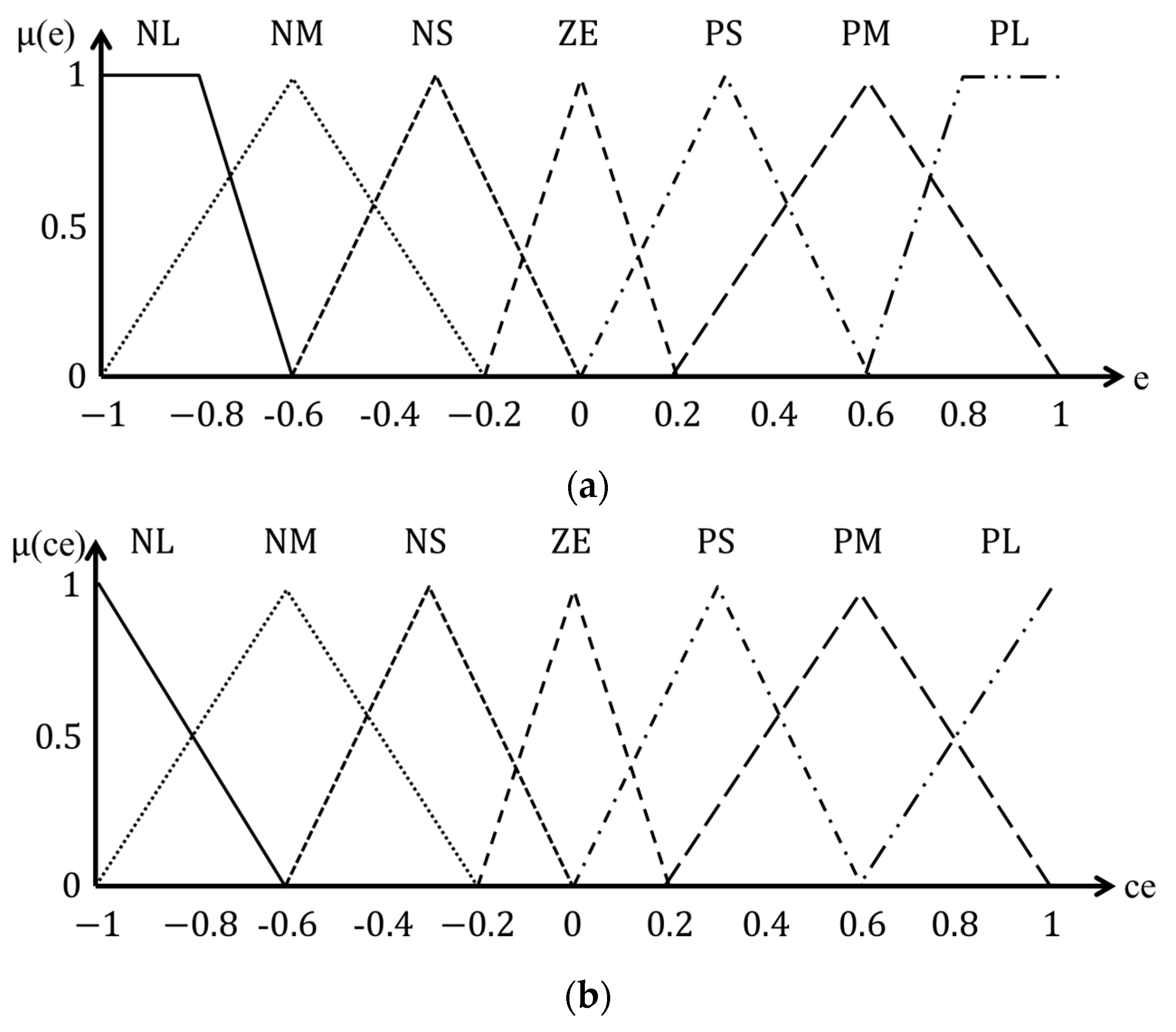
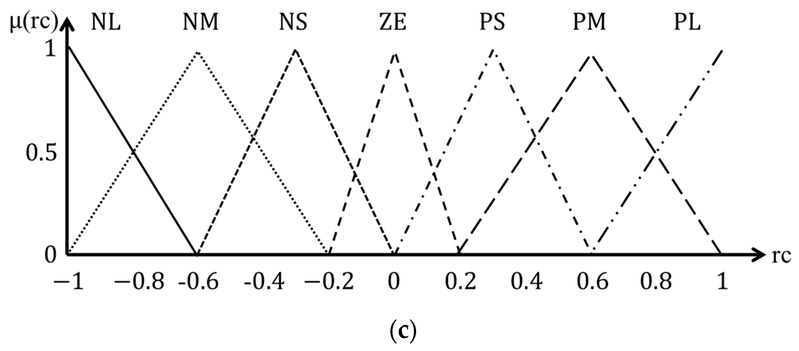
47]. If the level increases, the control variable is also increased by one level. This method can adjust the control amount in proportion to the change of the input value. The membership function of fuzzy control is shown
Figure 6. Membership functions use triangles and trapezoids the most. We use the triangle membership function which has advantages in real time control.
Figure 6 shows the membership function used in this paper. Fuzzy control is a control method that uses the ambiguity of the boundary; the fuzzy membership function shows the degree of membership of the input value. In this paper, membership range of membership function is used as follows. The required control amount according to the input value is set as Large, Medium, Small, and Zero according to the size, and it is divided into seven parts as positive and negative according to the control direction. The parameter of the membership function is used as a percentage of input value. For fast control speed, the range of NL, NM, PM, PL is set large, ZE is smallest, and NS and PS are medium. For this, we have designed membership function as follows; the range of ZE is −0.2 to 0.2, PS and NS are |0~0.6|, NM and PM are |0.2~1|, and NL and PL are |above 0.6|. In this paper, 49 rules were used. The number of rules affects computation time and system performance. If the number of rules is large, the calculation time increases but the control performance is the best [
48,
49,
50,
51]. Therefore, in this paper, we used 49 rules, which show the best control performance because the change in temperature is not fast.
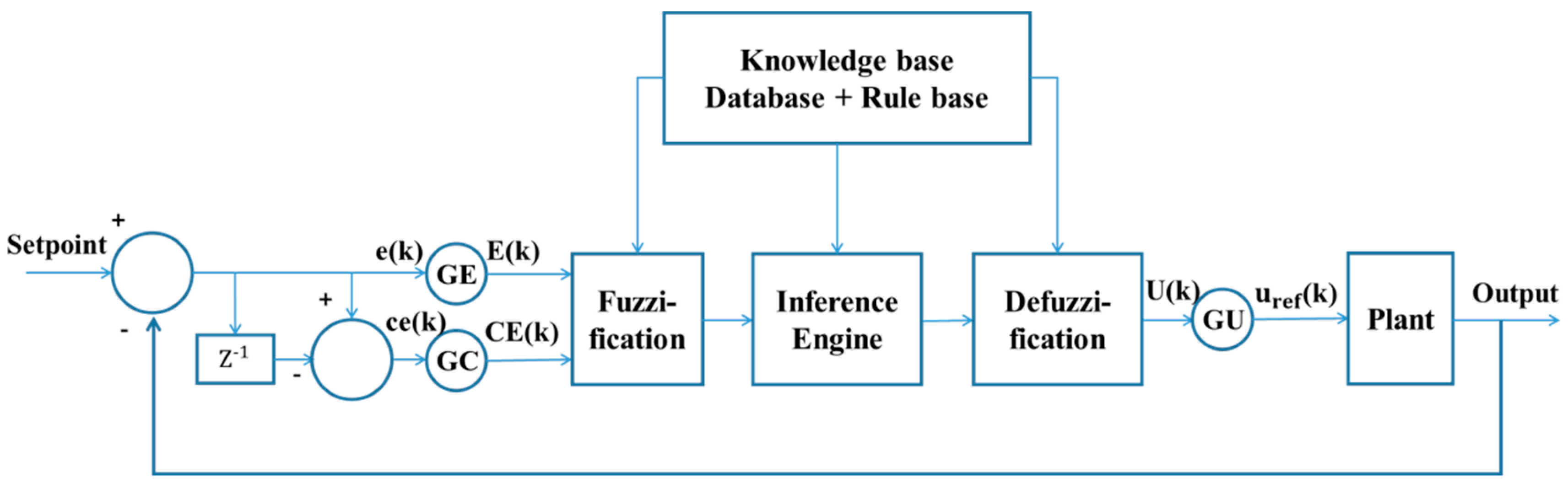
Figure 7 shows the general form of the fuzzy controller. The input to the fuzzy controller is the error and error value, and the gain values GE and GC are used to scale the input range −1 to 1 of the membership function of the graph. In addition, the output value through the defuzzification is multiplied by the gain value GU to scale it to a controllable variable [
29,
52,
53].
In this paper, the hot side of a thermoelectric device is cooled by a fan in a thermoelectric cooling system. Traditionally, the PI controller has difficulty selecting the suitable gain and is limited in performance improvement due to fixed gain. To improve its performance, this paper proposes a fuzzy proportional integration (FPI) controller that adjusts the input value of the PI controller by fuzzy control.
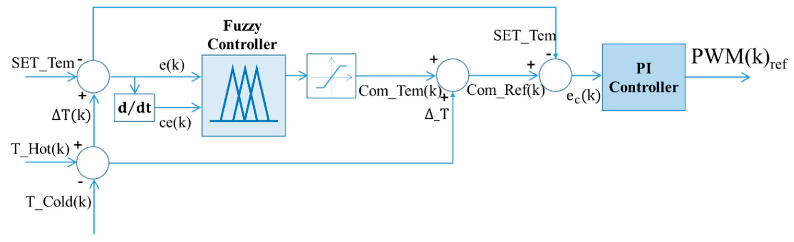
Figure 8 shows a block diagram of the FPI controller.
ΔT is the temperature difference between the hot side of the thermoelectric element (T_Hot) and the cold side (T_Cold), and SET_Tem is the set temperature difference. The fuzzy controller outputs the compensation temperature (Com_Tem), which compensates the temperature difference according to the operating state, with error and error change value inputs. ΔT is added to the compensation temperature (Com_Tem) and compared with the set temperature (SET_Tem), and the PI controller outputs a PWM (Pulse Width Modulation) signal for speed control of the fan. In this paper, the input value of PI is controlled by fuzzy control. In
Figure 7, the output (U) through the defuzzification is multiplied by the gain value (GU) to output the control value (
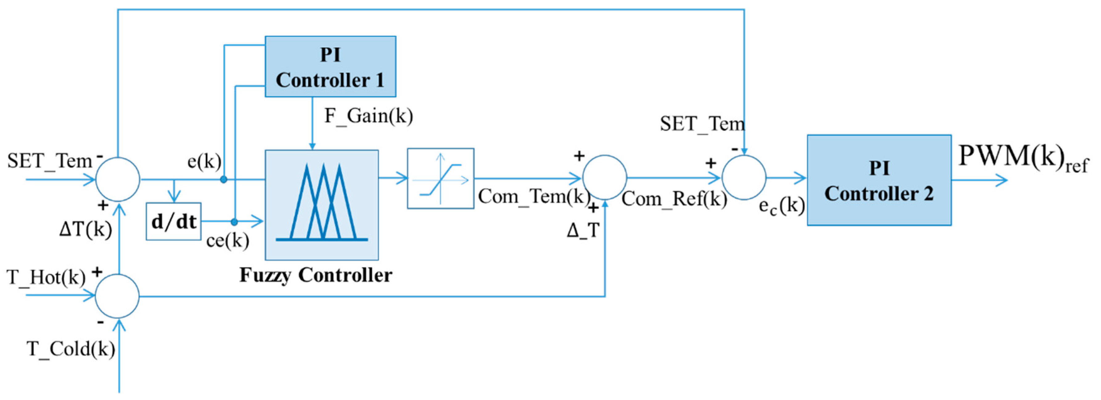
). This paper proposes a method to automatically adjust the output gain of fuzzy control according to the operating state. The output gain control of the fuzzy control uses a PI controller, and
Figure 9 shows a VFPI (variable gain fuzzy proportional integration) controller that adjusts the output gain of the fuzzy controller.
PI controller 1 outputs the output gain (F_Gain) of the fuzzy controller with the error (e) and the error change value (ce) as inputs.
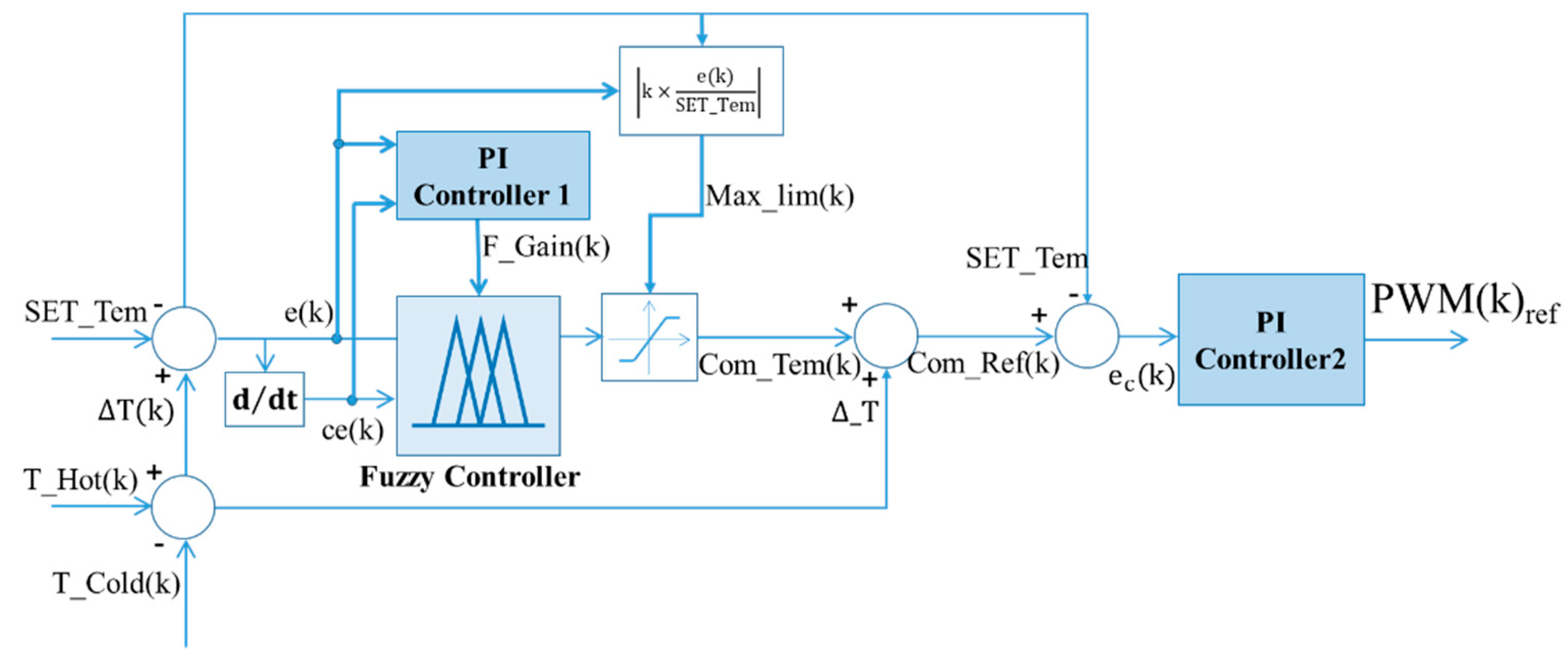
Generally, the output value of the controller uses a certain range of values for the stability of the control, and sets a limit value for this. If the limit value is too large, the control range may be exceeded. If the limit value is too small, the control response is slowed down. Therefore, this paper proposes a method which improves the response performance by adjusting the limit value according to the operating state of the system. The control state can be divided into a transient state and a steady state. The transient state requires a lot of changes to track the set value. The steady state decreases the control value to maintain the current state. Therefore, this paper proposes a method to adjust the limit value according to the ratio of the set value (SET_Tem) of the error value (e (k)) using equation 19. In the transient state, the limit value increases because the error value e (k) is large, and in the steady state, the error value e (k) decreases and the limit value decreases. As a result, a quick change is expected due to the control being performed at a larger value in the transient state, and the constant value is maintained by restricting the change of the control value in the steady state.
Figure 10 shows the VFPI-VL (variable gain fuzzy proportional integration with variable limit) controller which controls the limit value of the output value of the fuzzy controller.
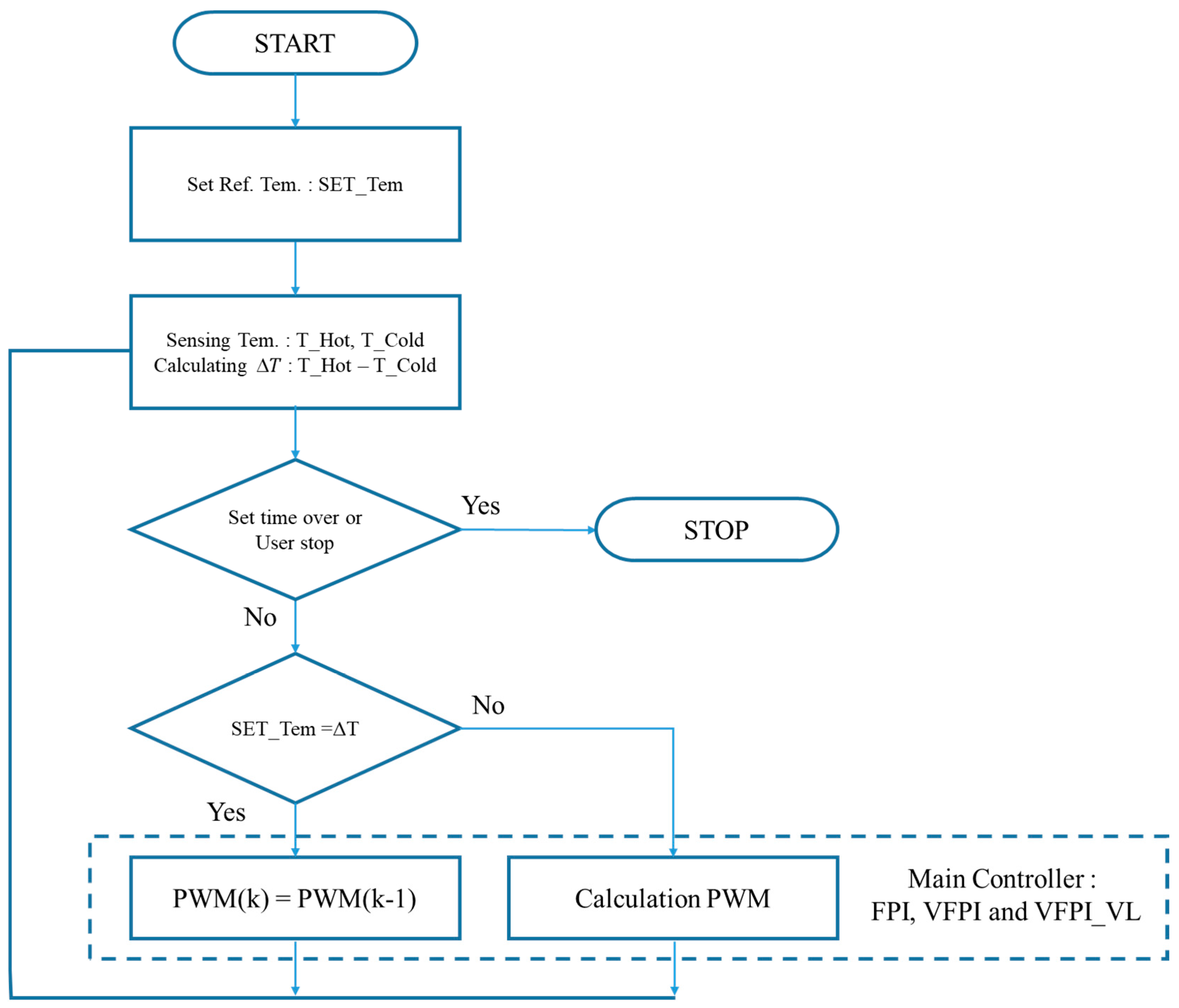
Figure 11 shows the flowchart for the PWM control that is the speed control signal of the fan. Set the reference temperature (Set_Tem) and calculate the temperature difference (
by measuring the temperature of the hot side (
) and cold side (
) of the thermoelectric element. This temperature difference is used to maintain the PWM through the main controller or to calculate a new PWM signal. The control ends when the set time is over or when the user enters the stop.
5. Experiment Result
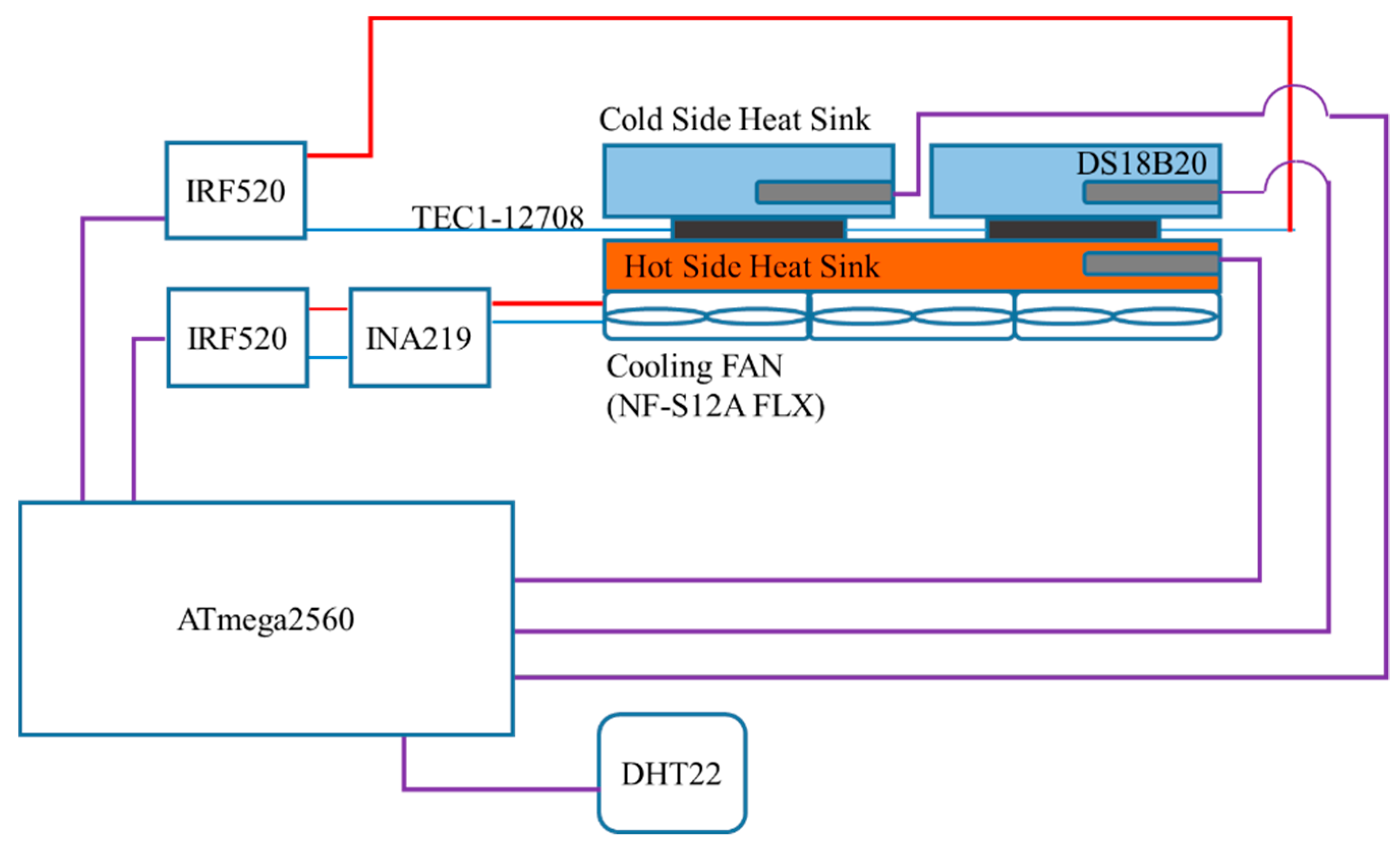
Figure 12 shows the configuration of the experimental device to test the performance of the proposed method and
Table 2 shows the characteristics of the main components used in the system configuration.
Arduino mega2580 (ARDUINO, Ivrea, Italy) is used as the main controller and a DS18B20 (DALLAS SEMICONDUCTOR, Dallas, TX, USA) temperature sensor is used for temperature of hot side and cold side of thermoelectric device. DHT22 (Aosong Electronics, Guangzhou, China) temperature/humidity sensor was used for ambient air temperature and IRF520 (VISHAY, Malvern, PA, USA) Power MOSFET for PWM control of thermoelectric device and fan. TEC1-12708 (HEBEI YUXIANG ELECTRONICS, HEBEI, China) is used as the thermoelectric element and NF-S12 FXL (Noctua, Wien, Austria) is used as the cooling fan. Details of the parts used are shown in
Table 2. The sampling period for the experiment is 1 s, and the switching frequency for PWM control is 980 Hz.
The process for performance testing was as follows.
Keep ambient temperature and humidity constant for experiment.
Operate the experimental device until the temperature of the hold side and cold side of the thermoelectric device is stabilized.
When the temperature of the thermoelectric element stabilizes, data is acquired at the set time intervals.
Repeat steps 1 to 3 for all control methods.
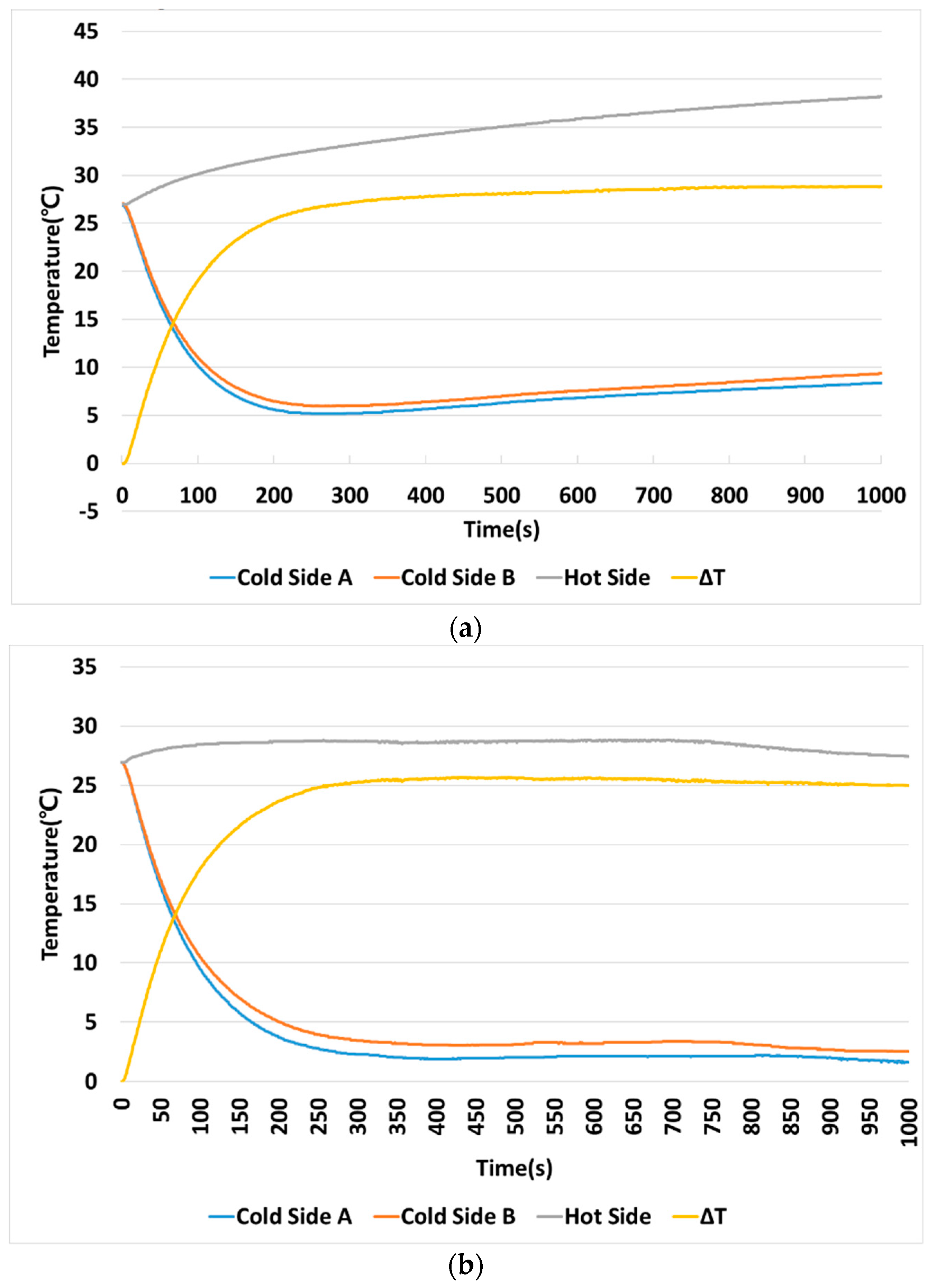
Figure 13 shows the temperature change according to the cooling performance on the hot side of the thermoelectric element.
Figure 13a shows the results when the hot side is not cooled, and
Figure 13b shows the results when cooling.
Table 3 shows the results of
Figure 13. When the hot side was cooled, the temperature of the hot side remained uniformly up to 28.81 °C, so that the cold side temperature could be cooled up to 1.56 °C. Therefore, cooling of the hot side is very important for cooling performance using a thermoelectric device.
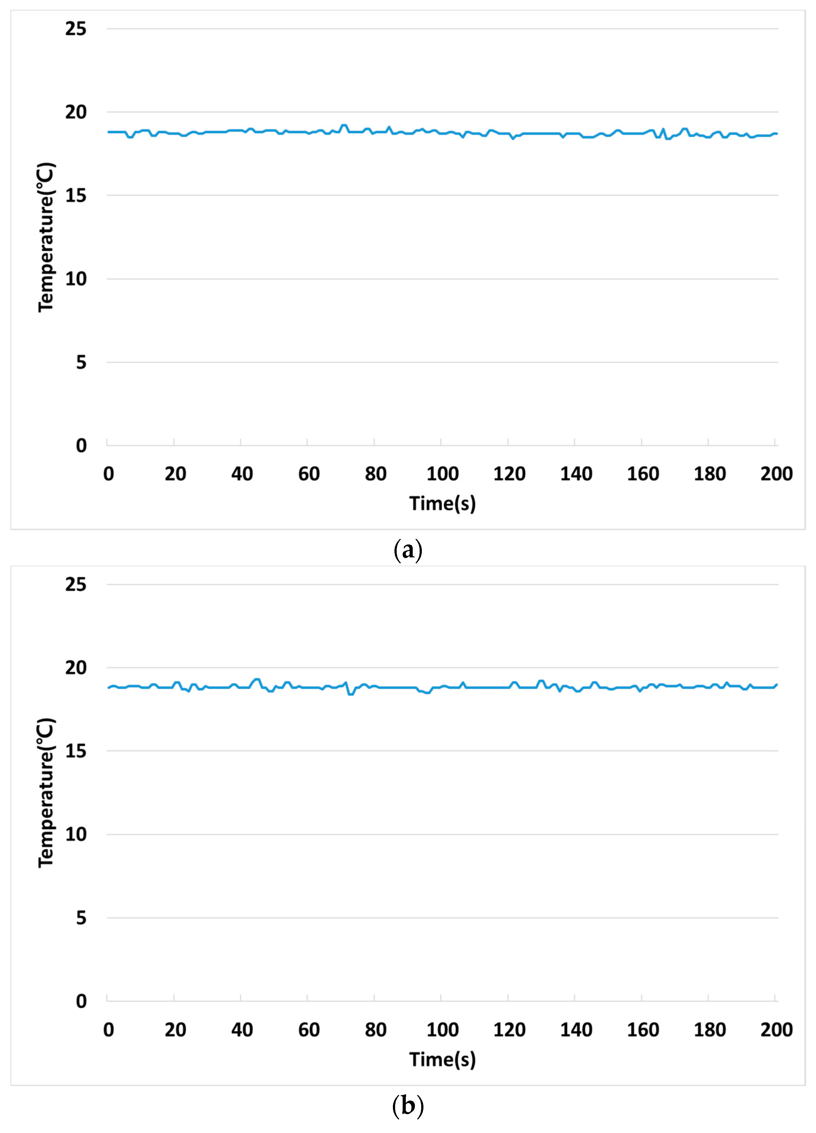
Figure 14 shows the ambient temperature conditions for the performance test of the PI control. The cooling performance using the fan is affected by the ambient temperature. Therefore, it is very important to match the ambient temperature conditions for performance comparison. In this paper, the cooling performance of the four methods is compared; the ambient temperature conditions for each performance comparison are as shown in
Table 4 and the experiment was conducted at very similar temperature conditions.
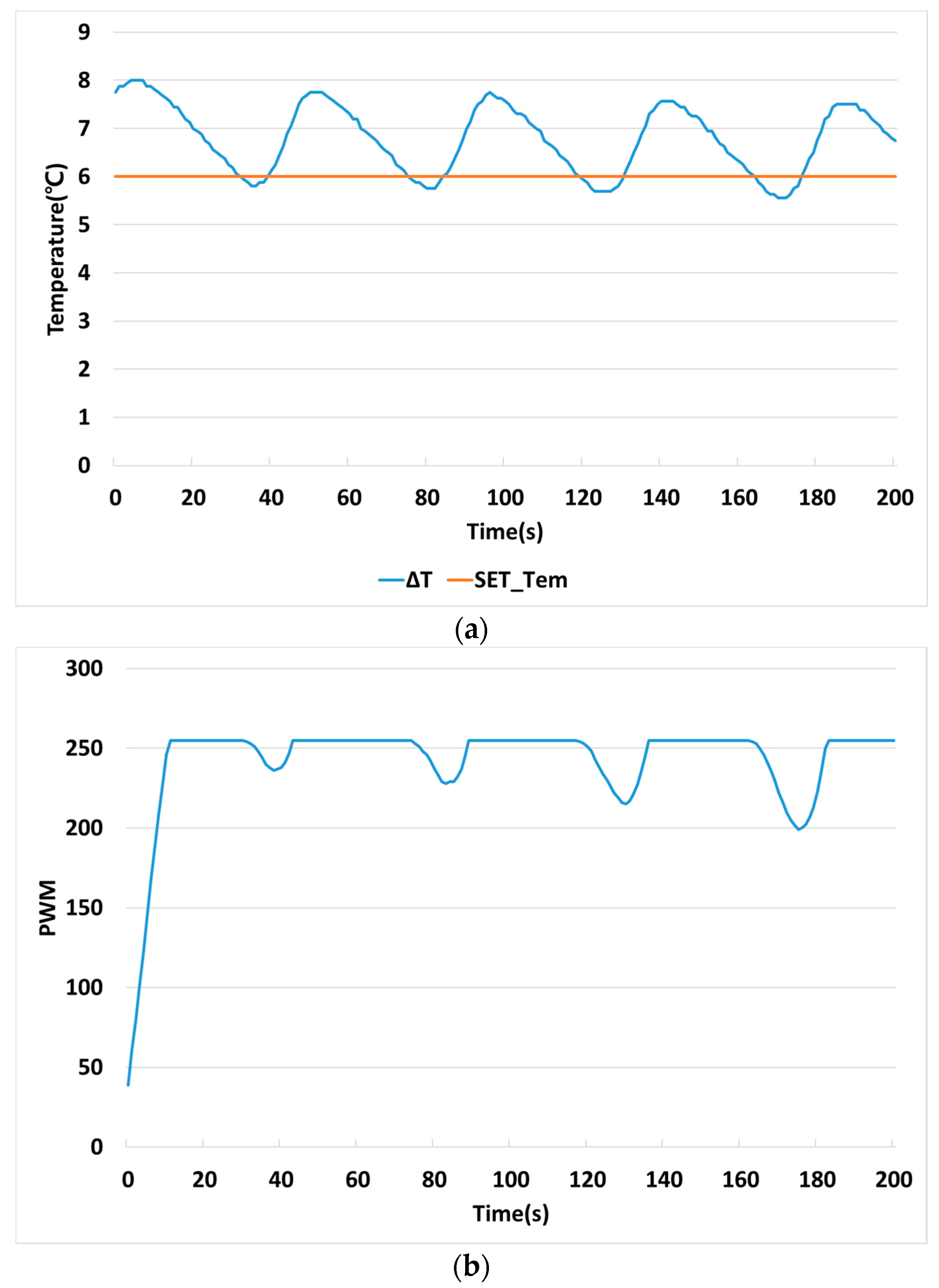
Figure 15 is the experimental result of the PI controller, which is used most in the industrial field. The ability to maintain a constant temperature difference between the cold side and the hot side for thermoelectric cooling was tested. The setting temperature difference (SET_Tem) between the cold side and the hot side was set to 6 °C, and the temperature difference (ΔT) was controlled accordingly.
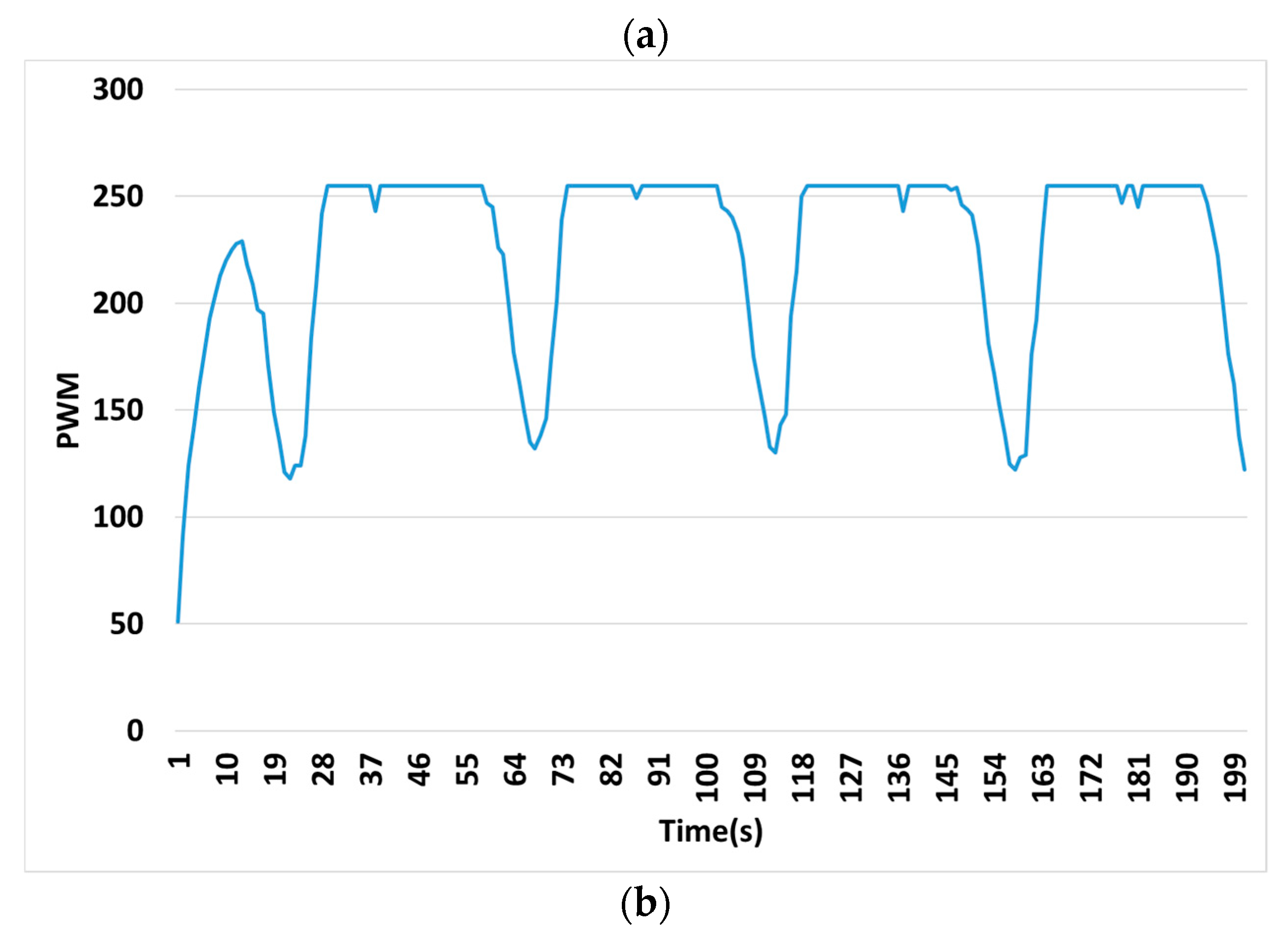
Figure 15a shows the temperature change and
Figure 15b shows the PWM signal for controlling the fan according to temperature. In case of Arduino, PWM is used from 0 to 255, PWM 0 means duty ratio 0%, and PWM 255 means duty ratio 100% [
54].
Table 5 shows the average temperature and the peak-to-peak temperature.
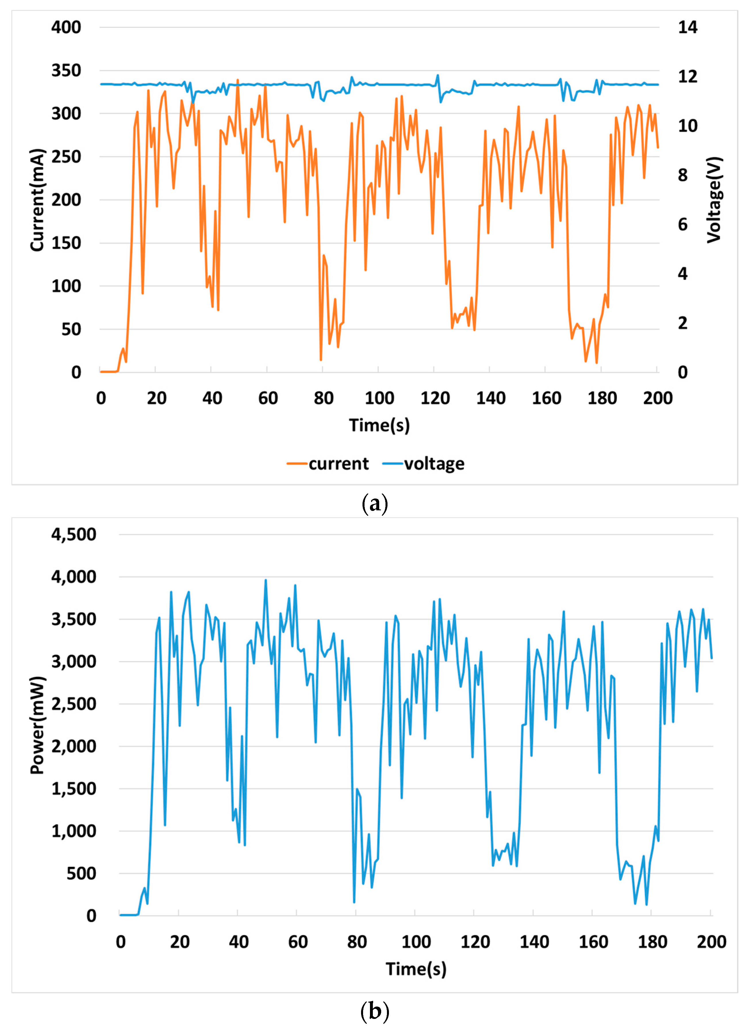
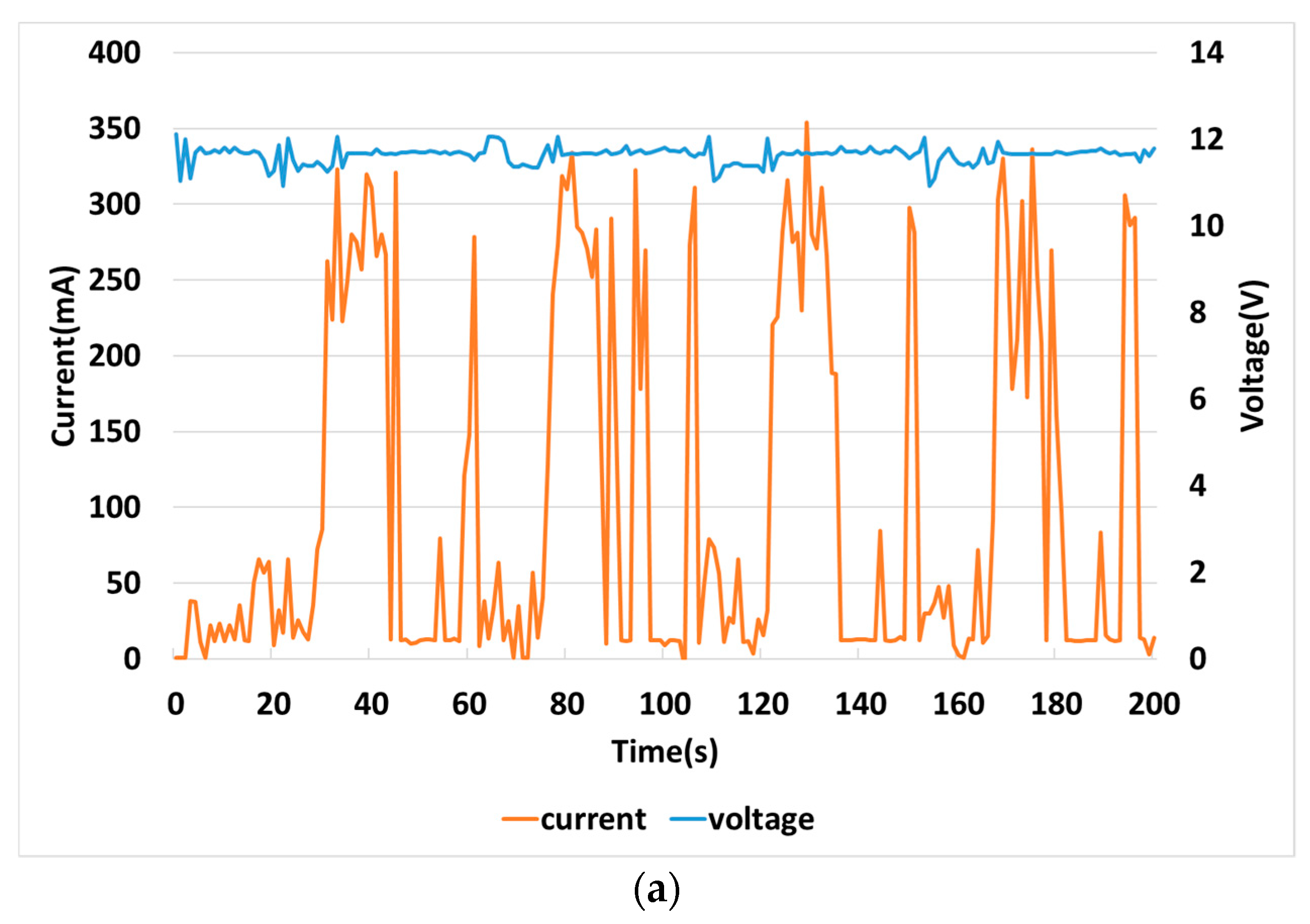
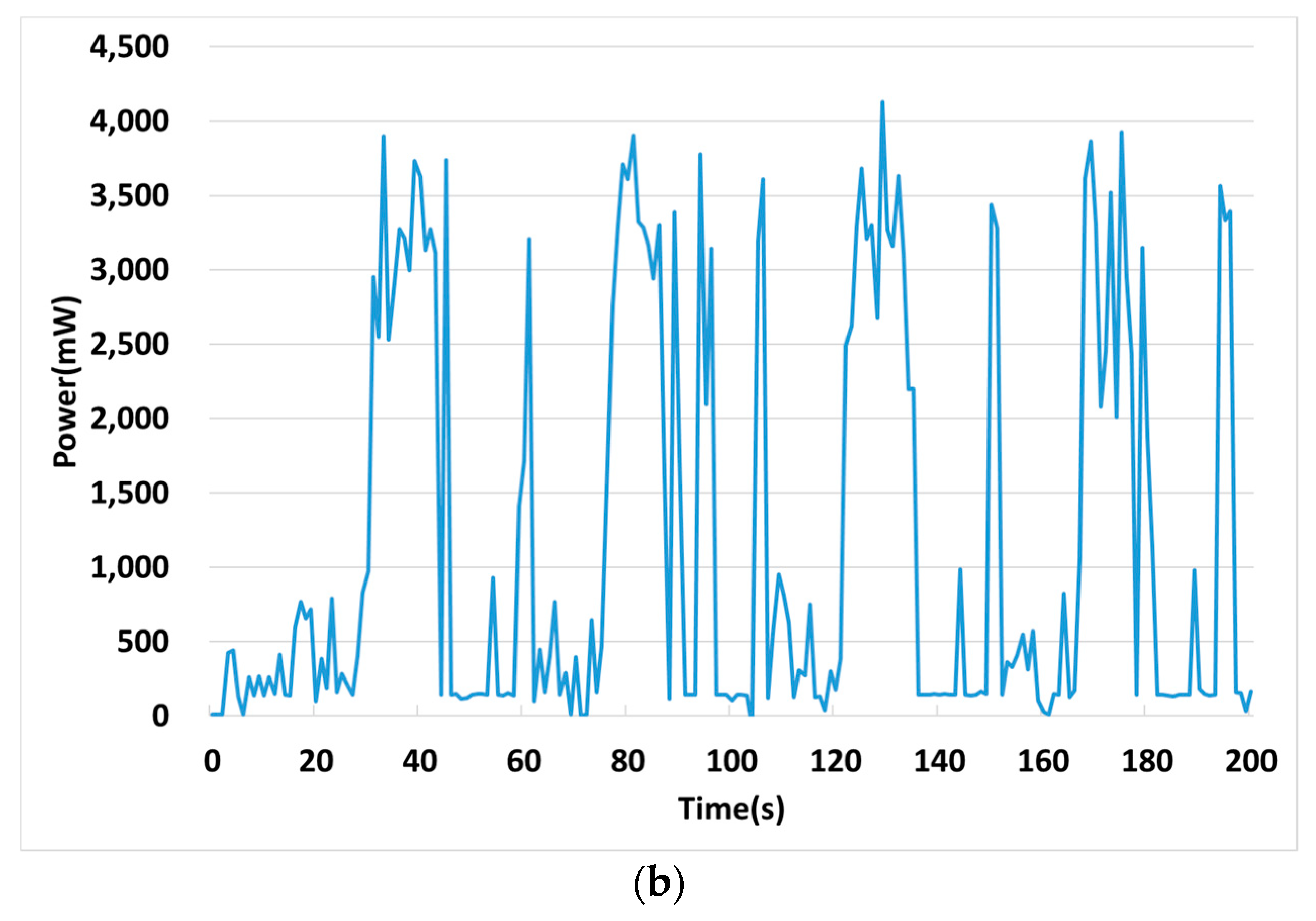
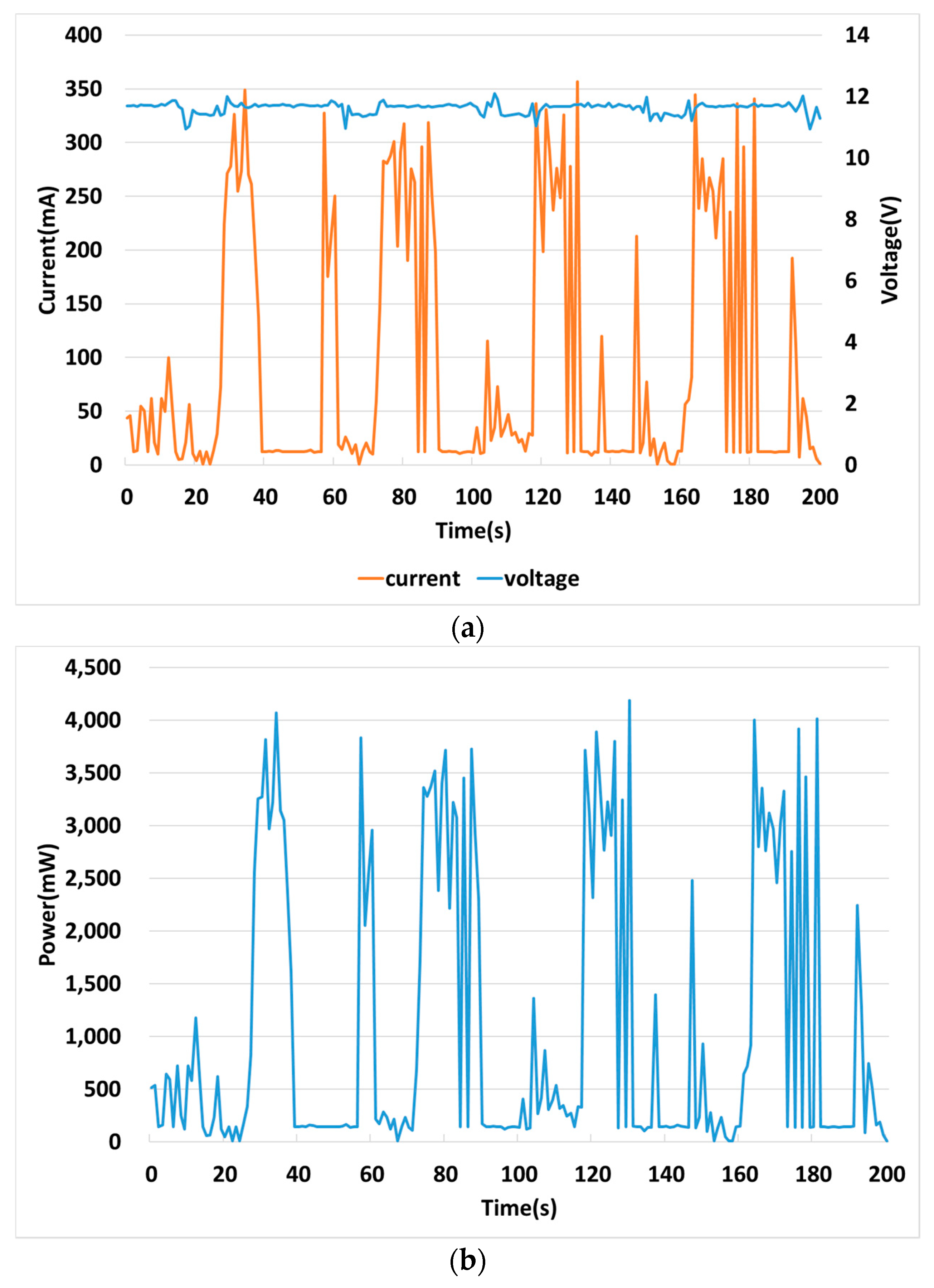
Figure 16 shows the power voltage, current, and power consumption of the PI controller. When the temperature is lower than the set temperature, the speed of the fan is lowered and the consumption current and power are reduced.
Table 6 shows the average current, voltage, and consumption power.
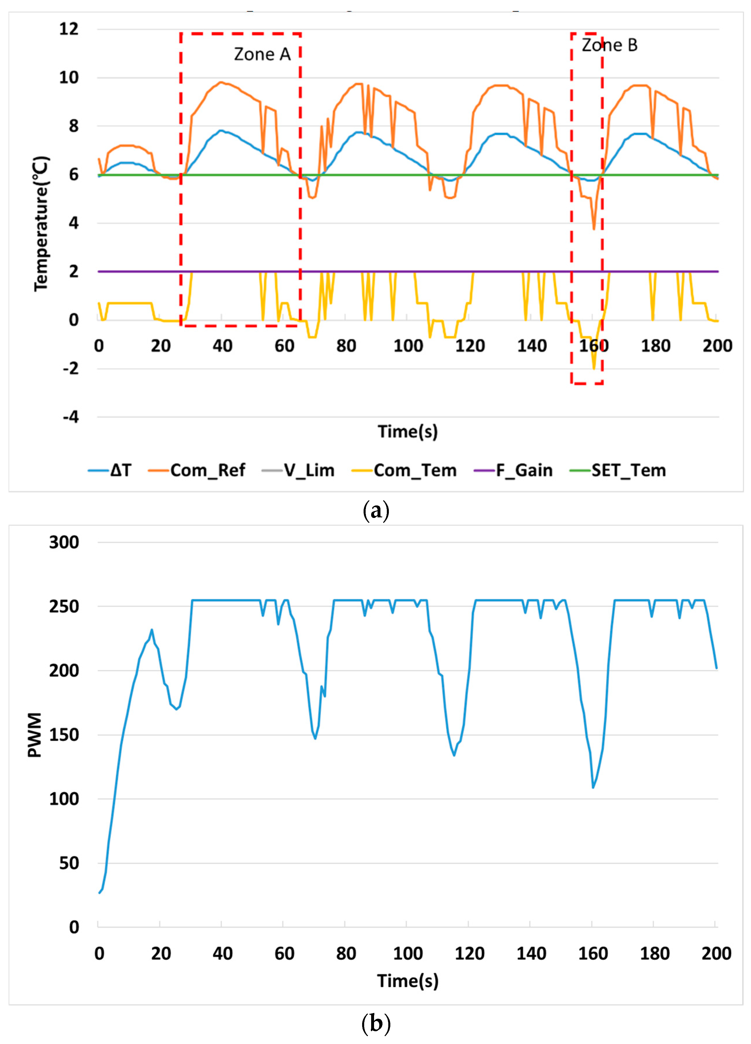
Figure 17 shows the temperature control results of the FPI controller using fuzzy control and the PI controller. In this paper, to improve the performance of the PI controller, the input value of the PI controller is adjusted by using the fuzzy controller. The set temperature difference between the cold side and the hot side of the thermoelectric element is set at 6 °C, and the temperature difference (ΔT) is controlled accordingly. In
Figure 17a, Com_Tem represents the temperature compensated by the fuzzy controller. This value adjusts the input value of the PI controller to Com_ref. In
Figure 17a, Zone A shows the temperature difference (ΔT) higher than the set temperature difference (SET_Tem). In this region, the speed of the fan needs to be increased because rapid cooling is required. In order for that to operate, the PI controller input value is amplified as the compensation temperature (com_Tem) increases. Zone B is a region in which the present temperature difference (ΔT) is lower than the set temperature difference (SET_Tem). In this interval, operation of the fan is not required and the compensation temperature (Com_Tem) is reduced. The PI controller amplifies the error value and thus enables more active temperature control.
Figure 17b shows the PWM signal by the FPI controller.
Figure 18 shows the input voltage, current, and power of the FPI controller.
Table 7 and
Table 8 show temperature characteristics, input voltage current, and power characteristics, respectively.
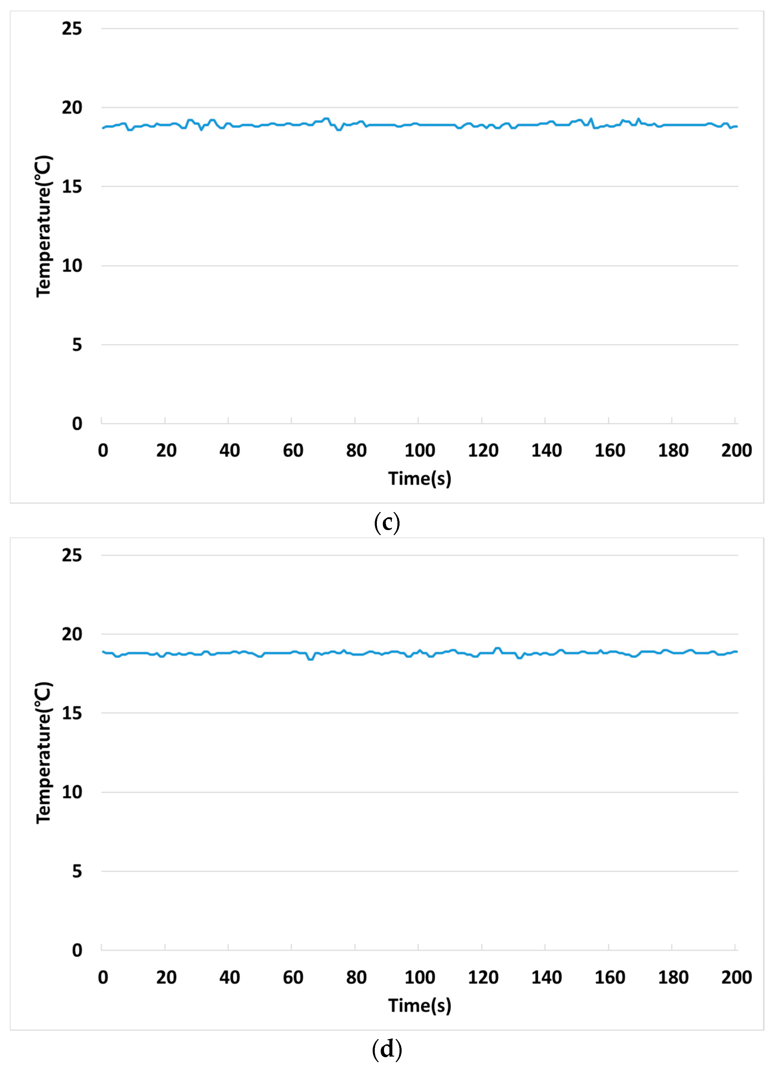
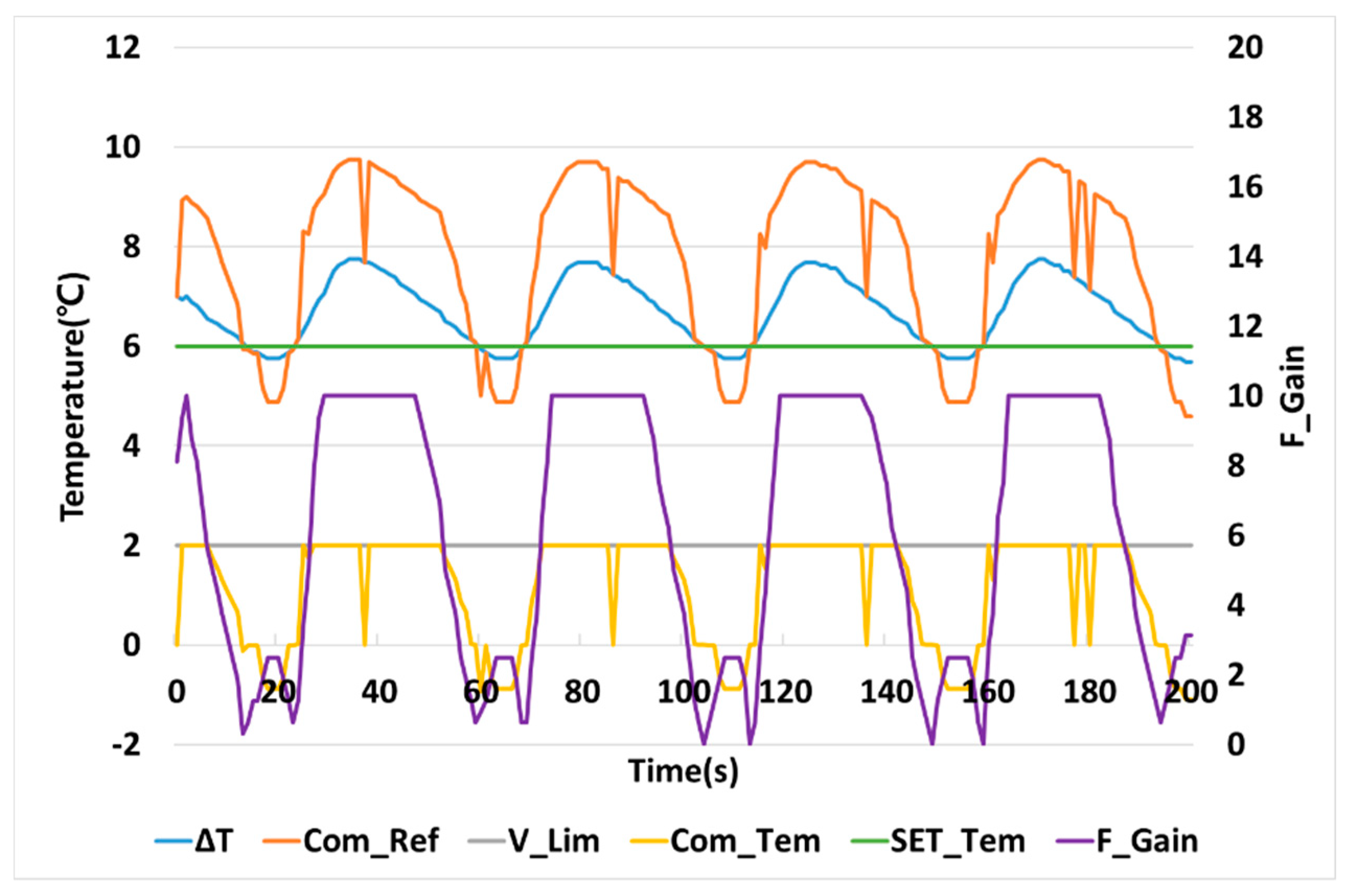
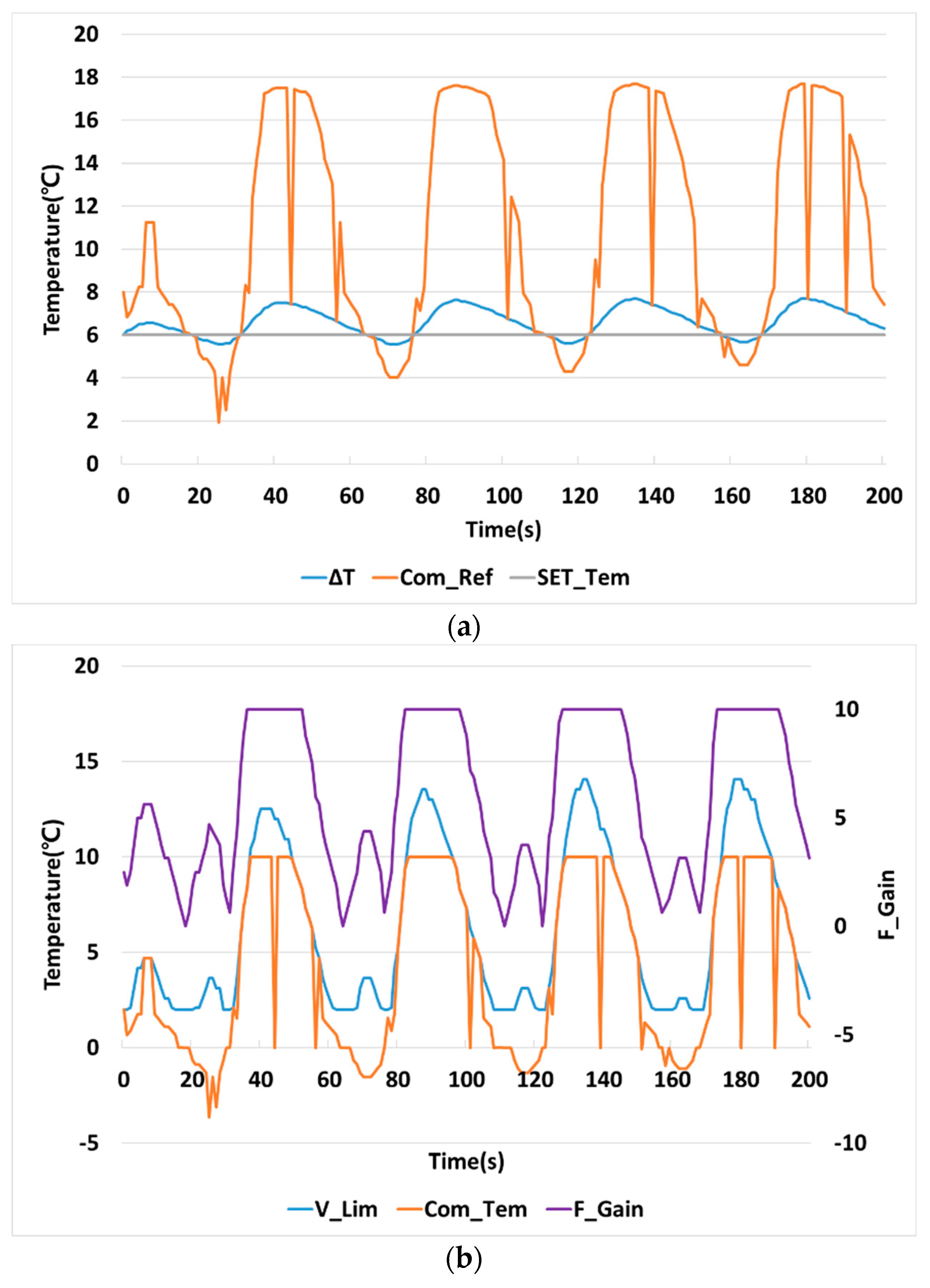
Figure 19 shows the temperature control result of VFPI that adjusts the gain of the fuzzy controller to improve the performance of the FPI. The FPI controller has a fixed gain of the fuzzy controller, but the VFPI controller changes the gain of the fuzzy controller to the PI controller according to the operating state. In
Figure 19a, F_Gain represents the gain value of the fuzzy controller controlled by the PI controller and is adjusted according to the error between the set temperature difference (SET_tem) and the present temperature difference (ΔT). Adjusting the gain of the fuzzy controller can change the fan speed more quickly.
Figure 19b shows the PWM signal by the VFPI controller.
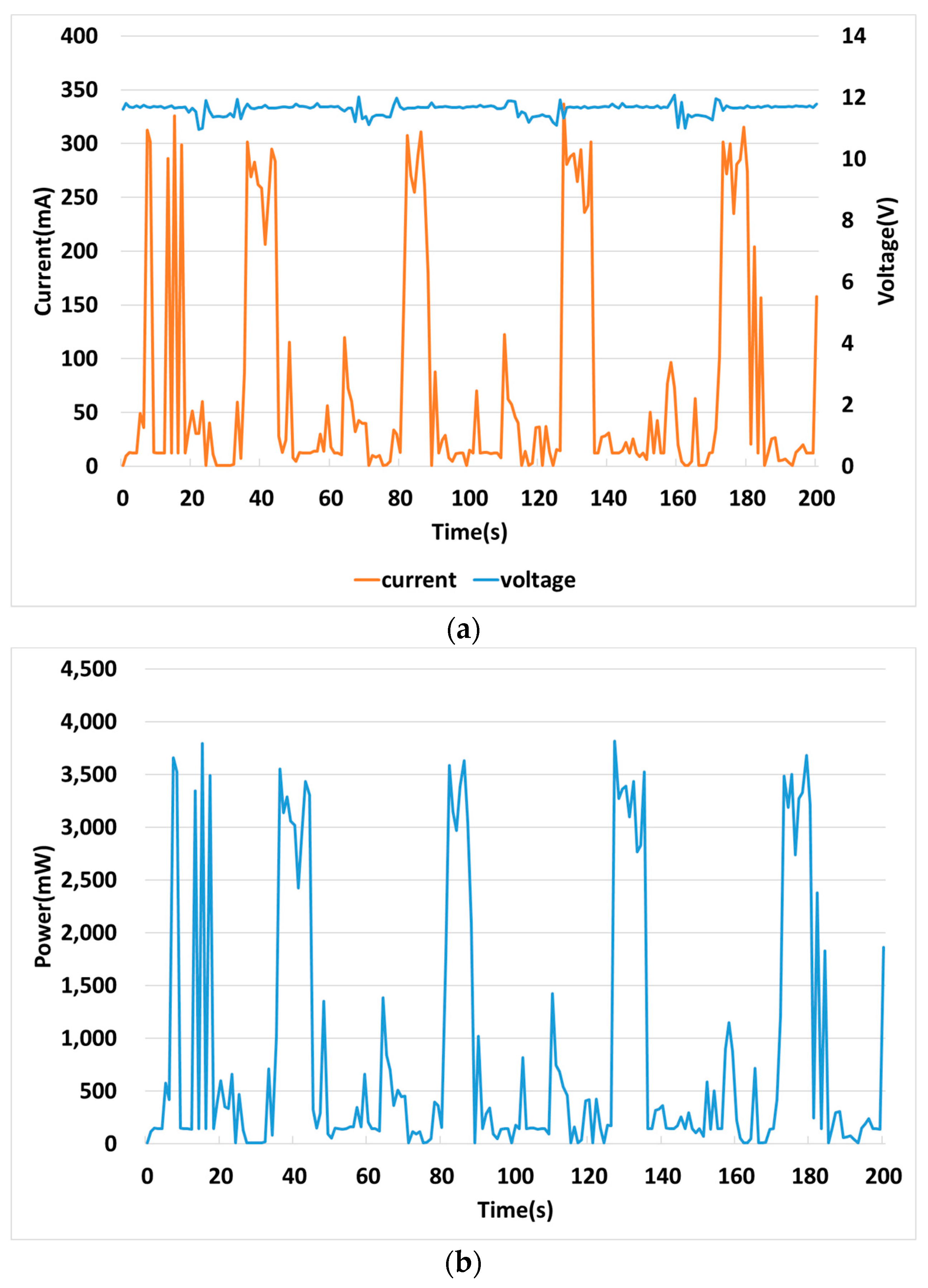
Figure 20 shows the input voltage, current, and power consumption of the VFPI controller.
Table 9 and
Table 10 show the respective results of
Figure 19 and
Figure 20.
Figure 21 shows the temperature control performance of variable fuzzy proportion integration-variable limit (VFPI-VL), which adjusts the limit value of the fuzzy controller to improve the performance of the VFPI controller. The VFPI-VL can be expected to produce fast speed changing because the limit value of the fuzzy controller is increasing. Fast speed changing improves the temperature control performance.
Figure 21c shows the PWM signal by the VFPI-VL controller.
Figure 22 shows input voltage, current and consumption power of the VFPI-VL controller.
Table 11 shows the average temperature and peak-to-peak temperature of the controllers compared in this paper. The maximum temperature difference between the FPI and the VFPI was the smallest in the Table, but the VFPI-VL did not differ greatly. The VFPI-VL at the average temperature was the closest to the set temperature of 6 °C.
Table 12 shows the average of the voltage, current, and power consumption of the controllers used in this paper. All of the voltages were similar, and the VFPI-VL controller showed the lowest current and power. In particular, when the PI controller consumes 100% of the power consumed, the FPI is 50.5%, the VFPI controller is 44.3%, and the VFPI-VL is 32.6%, and the power consumption is greatly reduced.
Table 12 shows the average of the voltage, current and power consumption of the controllers used in this paper. All of the voltages were similar, and the VFPI-VL controller showed the lowest current and power. In particular, when the PI controller consumes 100% of the power consumed, the FPI is 50.5%, the VFPI controller is 44.3%, and the VFPI-VL is 32.6%. The power consumption is greatly reduced. In addition, the average value of the PWM signal was the highest PI, and the VFPI-VL was the lowest.
In this paper, to improve the performance of the PI controller, which is most used in the industrial field, an FPI controller that controls the input value of the PI controller by a fuzzy controller is proposed. In addition, in order to improve the performance of the FPI controller, a VFPI controller that adjusts the gain of the fuzzy controller by the PI controller is proposed. Finally, a VFPI-VL method that changes the limit value of the fuzzy controller’s output value according to operating conditions is introduced.
In this paper, the proportional and integral gains of the PI controllers used in the four controllers are the same. The input value of the PI controller, the gain of the fuzzy controller and the limit value of the fuzzy controller’s output value are adjusted according to operating conditions. As a result, the fan cooling performance was improved. In particular, the VFPI-VL controller exhibited the best performance at constant temperature and power consumption.
6. Conclusions
This paper proposes a control method to improve energy efficiency and performance of the fan used in a cooling system. Industry 4.0 uses a lot of data. A large number of data centers are being built for this purpose. These data centers consist of IT equipment, power systems, cooling, and ventilation systems. Among them, cooling and ventilation systems have high rates of energy consumption. A cooling system using a fan is used as a general cooling system, and a cooling system using a thermoelectric element is used where cooling is required to a temperature lower than the ambient temperature or very precise temperature control is required. In order to maintain sufficient cooling performance in the cooling method using a thermoelectric element, the temperature of the hot side of the thermoelectric element must be continuously controlled. Therefore, this paper proposes various methods to improve the energy efficiency and performance of the fan which is mainly used in a cooling system. Generally, the PI controller is widely used for control. The PI controller is simple in structure and has a clear relationship between the gain and the control amount. However, the PI controller with a fixed gain value has limitations in performance improvement. The FPI controller adjusts the input value of the PI controller to the operating state using the fuzzy controller. The VFPI controller is a controller that adjusts the output gain value of the fuzzy controller used to adjust the gain of the PI controller. The VFPI-VL controller varies the limit value of the output value of the fuzzy controller according to the operation state.
In this paper, we propose a FPI method to control the input value of the PI controller, the VFPI controller to control the fuzzy controller output gain, and the VFPI-VL controller to adjust the output limit value of the fuzzy control. Each method enables faster control by amplifying the output according to the input value in the transient state. In particular, when the overshoot occurs, the control direction is reversed so that it can be stabilized more quickly. As a result, the rise time of the transient state was accelerated, and the stabilization time decreased in the steady state.
The controllers proposed in this paper actively control the temperature by adjusting the control variable value according to the operation state. This control performance improves the performance of the temperature maintaining ability, the average temperature, and the peak-to-peak temperature. The power consumption of the FPI controller, VFPI controller, and VFPI-VL controller was 50.5%, 44.3%, and 32.6%, respectively, of PI controller power consumption, thus improving the temperature control performance and energy efficiency. The methods presented in this paper can be applied to various variable speed systems as well as fans for cooling. The control methods presented through this paper have the disadvantage that the algorithm is complicated and the computational complexity is higher than that of the conventional PI controller. Therefore, research for improving processing speed through a microprocessor is needed.


