Artificial Intelligence-Based Discontinuous Reception for Energy Saving in 5G Networks

 ,
,  , ,
, ,
Abstract
:1. Introduction
- The communications in LTE do not consider beamforming, whereas in 5G networks UE has to align the best beam pair before the start of communications.
- The LTE-DRX mechanism has a fixed length of sleep duration, which increases the energy consumption and delay. Hence, LTE-DRX is not suitable for low latency communications in 5G networks.
- We perform the training of the LSTM neural network on wireless traffic. During training, LSTM network extracts the packet arrival time pattern from the wireless traffic trace. The prediction results show that the trained model predicts with minimum RMSE of 5 ms on random test set from trace 1 and 6 ms on random test set from trace 2, respectively.
- We devise DRX as a ten-state model.
- We propose an artificial intelligence based DRX mechanism for multiple beam communications in 5G networks. We suggest AI-DRX algorithm using ten state model to enable dynamic short or long sleep cycles, depending on the prediction results.
- We evaluate the performance of AI-DRX in terms of energy efficiency and mean delay. AI-DRX achieves the energy efficiency of on trace 1 and on trace 2, respectively; while considering the mean delay requirements of different services.
2. Related Work
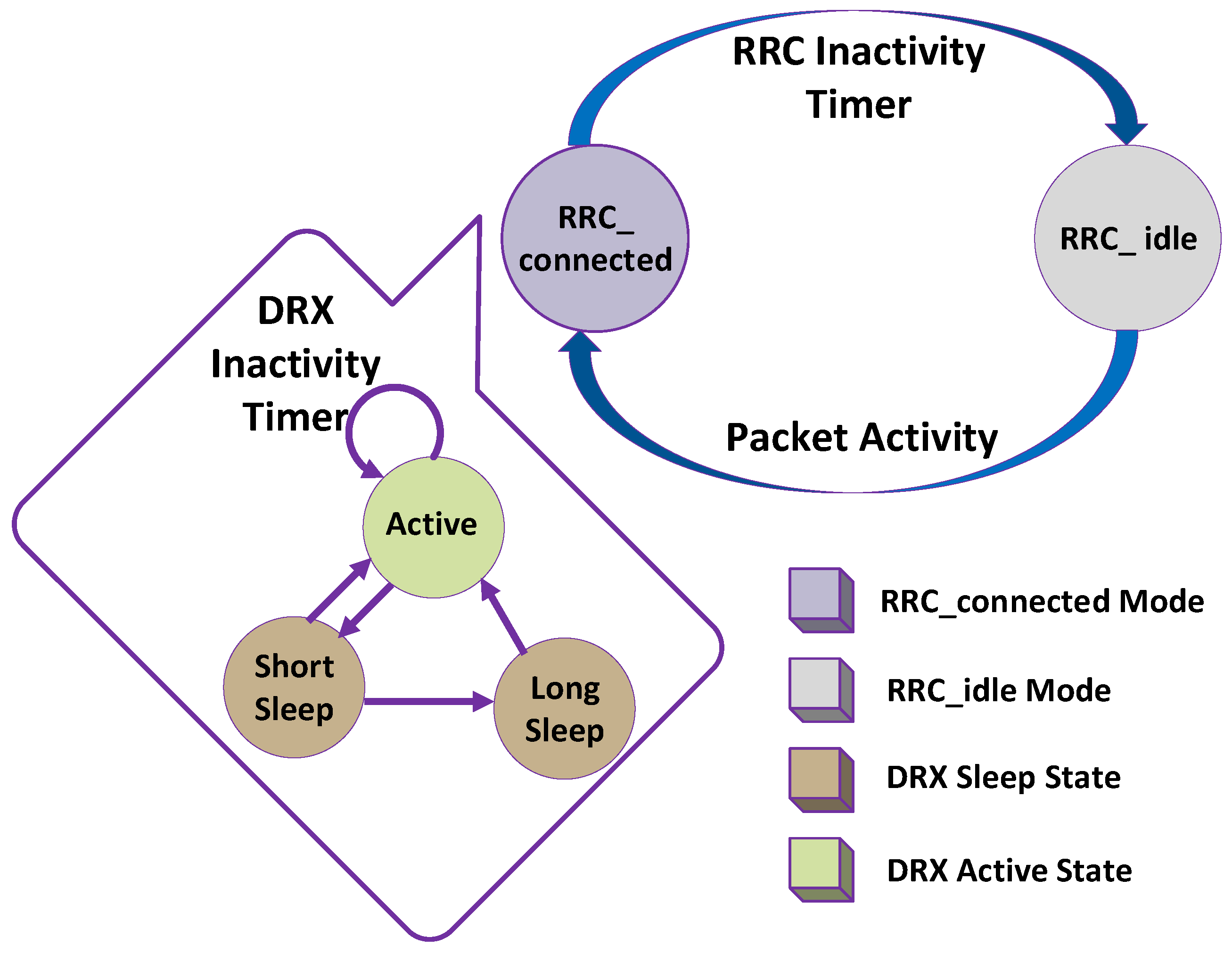
2.1. DRX in LTE
- Active State
- Sleep State
2.1.1. Active State
- Inactivity timer
- Active time
2.1.2. Sleep State
- ON time
- Short sleep cycle
- Short sleep timer
- Long sleep cycle
- Long sleep timer
2.2. Non-Compatibility of LTE-DRX for 5G Networks
2.3. Recurrent Neural Network for Predicting Sequential Data
3. AI-DRX for Multiple Beam Communications
3.1. System Model
- is the active time. A UE sends and receives the data during state. UE predicts the dynamic time during state.
- state is threshold comparison state. compares with both threshold values ( and ) to decide whether to remain in the active time or switch to the dynamic sleep cycle.
- state is dynamic short sleep cycle. It saves the UE power for a short period of time up to . The predicted value of in the dynamic sleep cycle is always lower than that of value in state.
- state highlights the dynamic long sleep cycle. It is similar to state but has a larger sleep period than . The predicted value of always has larger value of dynamic long sleep cycle than that of the dynamic short sleep cycle.
- state shows beam training during active time. This state allows UE to train and search for best available beam pairs between gNB and UE.
- state represents feedback after beam training operation in active time.
- state shows active time after best beam pairs are aligned. is different from as always occurs after beam training and feedback process. Moreover, enables UE to search beam pairs in active time until best beam pairs are found.
- state delineates beam training process after the execution of dynamic long or short sleep cycle.
- state is feedback operation that occurs after beam training and after the execution of dynamic long or short sleep cycle, respectively.
- state is the ON period, a UE only monitors PDCCH for an incoming packet. UE could not send or receive data packets during ON time.
3.2. Proposed AI-DRX Algorithm
- AI-DRX algorithm takes ON timer , minimum threshold value and maximum threshold value as input (Line 1).
- AI-DRX examines the buffer for any incoming data packets (Line 2).
- If any packet is received in the buffer, the packets will be served and the value of dynamic sleep time will be predicted, simultaneously (Line 4).
- During the active time, if no beam misalignment occurs between UE and gNB, AI-DRX compares the predicted value of dynamic sleep time with threshold values and .
- If the predicted value of dynamic sleep time is less than the minimum threshold value (Line 8), UE continues to remain in the active time (Line 9).
- If the predicted value of dynamic sleep time is greater than or equal to the minimum threshold value and less than maximum threshold value (Line 11). UE observes dynamic short sleep cycle (Line 12).
- In case of any beam misalignment after UE wakes up from dynamic short sleep cycle (Line 13), UE starts the beam training process (Line 14) and Feedback (Line 15) followed by ON time (Line 16).
- During ON time, if beam pairs are still misaligned (Line 17), UE searches beam pairs again (Line 18).
- During ON time, if a new packet arrives (Line 21), UE switches to active mode and start receiving data packets (Line 22).
- After completion of ON time, if no new packet arrives, UE continues to sleep for previous predicted time value of the long sleep cycle or short sleep cycle. respectively (Line 24).
- If is greater than (Line 28) the UE will go to dynamic long sleep cycle (Line 29).
- UE will perform beam training and feedback after completion of each dynamic long sleep cycle (Line 30).
- In the case of beam misalignment during an active time (Line 35), UE performs beam training (Line 36) and feedback (Line 37) and then re-enter active time (Line 38).
- During the active time (Line 38), if UE still find beam misalignment (Line 39), AI-DRX executes beam training process again (Line 40).
- After the alignment of beam pairs, the UE transits to active time (Line 42).
| Algorithm 1 AI based DRX for Multiple Beam Communications. |
| 1: Input , , |
| 2: Examine buffer for incoming packets |
| 3: if Packets in buffer > 0 then |
| 4: Serve the packets and Predict () |
| 5: else |
| 6: if No Beam Misalignment then |
| 7: Check () |
| 8: if then |
| 9: Go to Step 4 () |
| 10: else |
| 11: if then |
| 12: Go to Dynamic Short Sleep up to () |
| 13: if Beam Misalignment then |
| 14: Execute Beam Training () |
| 15: Feedback () |
| 16: ON () |
| 17: if No Beam Aligned then |
| 18: Go to Step 14 () |
| 19: end if |
| 20: else |
| 21: if New packet arrives before completion of ON Time then |
| 22: Go to Step 4 ( to ) |
| 23: else |
| 24: Go to Dynamic sleep for previous predicted time () |
| 25: end if |
| 26: end if |
| 27: else |
| 28: if then |
| 29: Go to Dynamic Long sleep () |
| 30: Go to Step 14 () |
| 31: end if |
| 32: end if |
| 33: end if |
| 34: else |
| 35: if Beam Misalignment then |
| 36: Execute Beam Training () |
| 37: Feedback () |
| 38: Active after Beam Training () |
| 39: if No Beam Aligned then |
| 40: Go to Step 36 () |
| 41: else |
| 42: Go to Step 4 () |
| 43: end if |
| 44: end if |
| 45: end if |
| 46: end if |
3.3. AI-DRX for Enabling Dynamic Long and Short Sleep Cycles
4. Performance Analysis
5. Conclusions
Author Contributions
Funding
Acknowledgments
Conflicts of Interest
References
- Ericsson Mobility Report June 2019. Available online: https://www.ericsson.com/assets/local/mobility-report/documents/2019/ericsson-mobility-report-june-2019.pdf (accessed on 12 June 2019).
- Fowler, S.; Shahidullah, A.O.; Osman, M.; Karlsson, J.M.; Yuan, D. Analytical evaluation of extended DRX with additional active cycles for light traffic. Comput. Netw. 2015, 77, 90–102. [Google Scholar] [CrossRef] [Green Version]
- Maheshwari, M.K.; Agiwal, M.; Saxena, N.; Roy, A. Directional Discontinuous Reception (DDRX) for mmWave enabled 5G Communications. IEEE Trans. Mobile Comput. 2018. [Google Scholar] [CrossRef]
- Agiwal, M.; Roy, A.; Saxena, N. Next generation 5G wireless networks: A comprehensive surve. IEEE Commun. Surv. Tut. 2016, 18, 1617–1655. [Google Scholar] [CrossRef]
- Zhou, K.; Nikaein, N.; Spyropoulos, T. LTE/LTE-A discontinuous reception modeling for machine type communications. IEEE Wireless Commun. Lett. 2013, 2, 102–105. [Google Scholar] [CrossRef]
- Maheshwari, M.K.; Roy, A.; Saxena, N. DRX over LAA-LTE—A New Design and Analysis based on Semi-Markov Model. IEEE Trans. Mob. Comput. 2018, 18, 276–289. [Google Scholar] [CrossRef]
- Ferng, H.-W.; Tseng, Y.-T.; Wang, T.-H. Parameter-Adaptive Dynamic and Adjustable DRX Schemes for LTE/LTE-A. IEEE Trans. Green Commun. Netw. 2019. [Google Scholar] [CrossRef]
- Gódor, I. Revitalizing DRX for enhanced mobile sleep modes. Comput. Commun. 2019, 138, 98–105. [Google Scholar] [CrossRef]
- 3GPP TSG-RAN WG2 #94 Tdoc R2-164023 Std. 2016. Available online: https://www.3gpp.org/ftp/tsg_ran/WG2_RL2/TSGR2_94/Docs/R2-164023.zip (accessed on 4 April 2019).
- Ho, C.H.; Huang, A.; Hsieh, H.-J.; Wei, H.-Y. Energy-Efficient Millimeter-Wave M2M 5G Systems with Beam-Aware DRX Mechanism. In Proceedings of the 2017 IEEE 86th Vehicular Technology Conference (VTC-Fall), Toronto, ON, Canada, 24–27 September 2017. [Google Scholar]
- Mudasar, L.M.; Maheshwari, M.K.; Shin, D.R.; Roy, A. Deep-DRX: A framework for deep learning–based discontinuous reception in 5G wireless networks. Trans. Emerg. Telecommun. Technol. 2019, 30, e3579. [Google Scholar]
- Kwon, S.-W.; Hwang, J.; Agiwal, A.; Kang, H. Performance analysis of DRX mechanism considering analogue beamforming in millimeter-wave mobile broadband system. In Proceedings of the 2014 IEEE Globecom Workshops (GC Wkshps), Austin, TX, USA, 8–12 December 2014. [Google Scholar]
- Liu, D.; Wang, C.; Rasmussen, L.K. Discontinuous Reception for Multiple-Beam Communication. IEEE Access 2019, 7, 46931–46946. [Google Scholar] [CrossRef]
- Wang, J.; Tang, J.; Xu, Z.; Wang, Y.; Xue, G.; Zhang, X.; Yang, D. Spatiotemporal modeling and prediction in cellular networks: A big data enabled deep learning approach. In Proceedings of the IEEE INFOCOM 2017—IEEE Conference on Computer Communications, Atlanta, GA, USA, 1–4 May 2017. [Google Scholar]
- Gers, A.F.; Schmidhuber, J.; Cummins, F.A. Learning to forget: Continual prediction with LSTM. Neural Comput. 1999, 12, 850–855. [Google Scholar]
- Google. Google AI Blog. Available online: https://ai.googleblog.com/2018/05/duplex-ai-system-for-natural-conversation.html (accessed on 1 June 2019).
- Bontu, C.S.; Illidge, E. DRX mechanism for power saving in LTE. IEEE Commun. Mag. 2009, 47, 48–55. [Google Scholar] [CrossRef]
- Evolved universal terrestrial radio access (E-UTRA); Medium access control (MAC) protocol specification. Available online: https://portal.3gpp.org/desktopmodules/Specifications/SpecificationDetails.aspx?specificationId=2437 (accessed on 2 March 2018).
- Chang, H.-L.; Tsai, M.-H. Optimistic DRX for Machine-Type Communications in LTE-A Network. IEEE Access 2018, 6, 9887–9897. [Google Scholar] [CrossRef]
- Chang, H.-L.; Lu, S.-L.; Chuang, T.-H.; Lin, C.-Y.; Tsai, M.-H.; Sou, S.-I. Optimistic DRX for machine-type communications. In Proceedings of the 2016 IEEE International Conference on Communications (ICC), Kuala Lumpur, Malaysia, 22–27 May 2016. [Google Scholar]
- Agiwal, M.; Maheshwari, M.K.; Saxena, N.; Roy, A. Directional-DRX for 5G wireless communications. Electron. Lett. 2016, 52, 1816–1818. [Google Scholar] [CrossRef]
- Maheshwari, M.K.; Agiwal, M.; Saxena, N.; Roy, A. Hybrid directional discontinuous reception (HD-DRX) for 5G communication. IEEE Commun Lett. 2017, 21, 1421–1424. [Google Scholar] [CrossRef]
- Maheshwari, M.K.; Roy, A.; Saxena, N. Analytical modeling of DRX with flexible TTI for 5G communications. Trans. Emerg. Telecommun. Technol. 2018, 29, e3275. [Google Scholar] [CrossRef]
- Study on new radio access technology Physical layer aspects. Available online: https://portal.3gpp.org/desktopmodules/Specifications/SpecificationDetails.aspx?specificationId=3066 (accessed on 2 March 2018).
- Study on new radio access technology Radio interface protocol aspects. Available online: https://portal.3gpp.org/desktopmodules/Specifications/SpecificationDetails.aspx?specificationId=3070 (accessed on 2 March 2018).
- Rumelhart, D.E.; Hinton, G.E.; Williams, R.J. Learning Internal Representations by Error Propagation; Technical Report; Institute for Cognitive Science, University of California: San Diego, CA, USA, 1985. [Google Scholar]
- UMass Trace Repository. ACM MMSys conference dataset archive. Available online: http://traces.cs.umass.edu/index.php/Mmsys/Mmsys (accessed on 2 March 2018).
- CRAWDAD Data Set Cambridge/Inmotion. Available online: https://crawdad.org/cambridge/inmotion/20051001 (accessed on 2 March 2018).
- Baughman, M.; Haas, C.; Wolski, R.; Foster, I.; Chard, K. Predicting Amazon spot prices with LSTM networks. In Proceedings of the 9th Workshop on Scientific Cloud Computing, Tempe, AZ, USA, 11 June 2018. [Google Scholar]
- Policy and charging control architecture. Available online: https://portal.3gpp.org/desktopmodules/Specifications/SpecificationDetails.aspx?specificationId=810 (accessed on 2 March 2018).
- Liang, J.M.; Chen, J.-J.; Cheng, H.-H.; Tseng, Y.-C. An energy-efficient sleep scheduling with QoS consideration in 3GPP LTE-advanced networks for internet of things. IEEE J. Emerg. Sel. Top. Circ. Syst. 2013, 3, 13–22. [Google Scholar] [CrossRef]
- Tseng, C.-C.; Wang, H.-C.; Kuo, F.-C.; Ting, K.-C.; Chen, H.-H.; Chen, G.-Y. Delay and power consumption in LTE/LTE-A DRX mechanism with mixed short and long cycles. IEEE Trans. Veh. Technol. 2015, 65, 1721–1734. [Google Scholar] [CrossRef]
- Huang, B.; Tian, H.; Chen, L.; Zhu, J. DRX-aware scheduling method for delay-sensitive traffic. IEEE Commun. Lett. 2010, 14, 1113–1115. [Google Scholar]


| Abbreviation | Notation | Abbreviation | Notation |
|---|---|---|---|
| Forget gate | DRX active time | ||
| Input modulation gate | DRX ON time | ||
| Input gate | DRX Inactivity timer | ||
| Output layer | Packet inter-arrival time | ||
| Cell state | DRX Dynamic sleep time | ||
| Output modulation gate | Weight corresponding to each gate |
| Type | Qos Class Identifier | Packet Loss Rate | Packet Delay Budget | Examples |
|---|---|---|---|---|
| GBR | 1 | 100 ms | Voice services | |
| GBR | 2 | 150 ms | Live streaming services | |
| GBR | 3 | 50 ms | Real time gaming services | |
| GBR | 4 | 300 ms | Buffered streaming services | |
| Non-GBR | 5 | 100 ms | IMS Signaling services | |
| Non-GBR | 6 | 300 ms | TCP based application services | |
| Non-GBR | 7 | 100 ms | Interactive gaming services | |
| Non-GBR | 8 | 300 ms | TCP based video services | |
| Non-GBR | 9 | 300 ms | TCP based video services |
© 2019 by the authors. Licensee MDPI, Basel, Switzerland. This article is an open access article distributed under the terms and conditions of the Creative Commons Attribution (CC BY) license (http://creativecommons.org/licenses/by/4.0/).
Share and Cite
Memon, M.L.; Maheshwari, M.K.; Saxena, N.; Roy, A.; Shin, D.R. Artificial Intelligence-Based Discontinuous Reception for Energy Saving in 5G Networks. Electronics 2019, 8, 778. https://doi.org/10.3390/electronics8070778
Memon ML, Maheshwari MK, Saxena N, Roy A, Shin DR. Artificial Intelligence-Based Discontinuous Reception for Energy Saving in 5G Networks. Electronics. 2019; 8(7):778. https://doi.org/10.3390/electronics8070778
Chicago/Turabian StyleMemon, Mudasar Latif, Mukesh Kumar Maheshwari, Navrati Saxena, Abhishek Roy, and Dong Ryeol Shin. 2019. "Artificial Intelligence-Based Discontinuous Reception for Energy Saving in 5G Networks" Electronics 8, no. 7: 778. https://doi.org/10.3390/electronics8070778