Article

Low-Profile Frequency Reconfigurable Antenna for Heterogeneous Wireless Systems

1
Centre For Wireless Technology, Faculty of Engineering, Multimedia University Cyberjaya, Selangor 63100, Malaysia
2
Department of Medical Equipment Technology, College of Applied Medical Sciences, Majmaah University, AlMajmaah 11952, Saudi Arabia
3
Unit of Research in High Frequency Electronic Circuits and Systems, Faculty of Mathematical, Physical and Natural Sciences of Tunis, Tunis El Manar University, Tunis 2092, Tunisia
4
Computer Science Department, Cihan University Slemani, Sulaimaniya 46002, Iraq
5
Department of Electrical Engineering, Hashemite University, Zarqa 13115, Jordan
6
College of Engineering, Al Ain University (AAU), Al Ain 64141, UAE
7
Instituto de Telecomunicações, Campus Universitário de Santiago, 3810-193 Aveiro, Portugal
8
School of Electrical Engineering, University of Ulsan, Ulsan 44610, Korea
*
Author to whom correspondence should be addressed.
Electronics 2019, 8(9), 976; https://doi.org/10.3390/electronics8090976
Submission received: 5 August 2019 / Revised: 27 August 2019 / Accepted: 30 August 2019 / Published: 31 August 2019
(This article belongs to the Special Issue Recent Technical Developments in Energy-Efficient 5G Mobile Cells)

Abstract

:
A low-profile (0.21 λ g × 0.35 λ g × 0.02 λ g ) and a simply-structured frequency-switchable antenna with eight frequency choices is presented in this paper. The radiating structure (monopole) is printed on a 1.6-mm thicker, commercially-available substrate of FR-4 ( ϵ r = 4.4, tan δ = 0.020). Specifically, it uses three PIN diodes in the designated places to shift the resonant bands of the antenna. The antenna operates at four different modes depending on the ON and OFF states of the PIN diodes. While in each mode, the antenna covers two unique frequencies (Mode 1 = 1.8 and 3.29 GHz, Mode 2 = 2.23 and 3.9 GHz, Mode 3 = 2.4 and 4.55 GHz, and Mode 4 = 2.78 and 5.54 GHz). The performance results show that the proposed antenna scheme explores significant gain (>1.5 dBi in all modes) and reasonable efficiency (>82% in all modes) for each mode. Using a high-frequency structure simulator (HFSS), the switchable antenna is designed and optimized. The fabricated model along with the PIN diode and biasing network is tested experimentally to validate the simulation results. The proposed antenna may also be combined in compact and heterogeneous radio frequency (RF) front-ends because of its small geometry and efficient utilization of the frequency spectrum.

1. Introduction

Recent advancements in wireless communication systems need transceivers to be efficiently utilized with heterogeneous systems such as wireless local area network (WLAN), Worldwide Interoperability for Microwave Access (WiMAX), Long-Term Evolution (LTE), Fourth-Generation (4G), LTE Advanced Pro (4.5G), Fifth-Generation (5G), and many more [1]. One of the important components of the transceiver is antenna. The antenna being an important component of the transceiver occupies a major portion of the system [2,3]. The size increases further by incorporating any tuning mechanism in it. Since, the antenna required for modern transceivers must be compact and frequency switchable to meet the standard of the transceivers. In this regards, many approaches have been used to reduce the size of the antenna and to make it tunable for many useful applications.
The antenna which is capable of switching its resonant band according to the user requirement, is known as a frequency-reconfigurable antenna. Various techniques have been adopted to change the surface current distribution of the antenna, which produces a highly-reconfigurable antennas. In [4,5], the lumped element between the monopole and the parasitic patch is used to switch the antenna from a single band to a dual band. A compact-sized frequency-reconfigurable antenna for mobile handsets is reported in [6]. The reported antenna in [6] covers Long-Term Evolution (LTE) LTE700, LTE2300, LTE2500, Global System for Mobile (GSM) GSM850, GSM900, GSM1800, GSM1900, and Universal Mobile Telecommunications System (UMTS) (1920–2170 MHz) bands for different switching conditions. A minimally-sized hexagonally-shaped reconfigurable slot antenna for WLAN is reported in [7]. The reported antenna covers dual bands (2.4 and 5.2 GHz) and a single band (2.4 GHz) for the PIN diode in the ON and OFF states, respectively. Two different types of frequency-reconfigurable antennas are reported in [8] for multiband applications. The reported antenna covers three bands: the Wireless Fidelity (WiFi) band, the Worldwide Interoperability for Microwave Access (WiMAX) band, and the WLAN band, for different biasing conditions of PIN diodes. Furthermore, a frequency-reconfigurable implantable antenna for the Medical Implant Communications Services (MICS: 402–405 MHz) and Industrial, Scientific, and Medical (ISM: 902–928 MHz) band is examined in [9]. Micro-electromechanical switches (MEMSs) are used in [10] to reconfigure the operating band of the antenna. However, the reported antenna cannot be efficiently used with any planner and compact components due to its large dimensions and 3D geometry. Following that, a polarization and frequency-reconfigurable antenna is reported in [11]. The optical switches are inserted between the main monopole and the parasitic patch in [12] to achieve different frequency responses with a wider bandwidth and high gain at the cost of a large antenna size. In [13], the PIN diode on the multi-layer antenna, control the patch and feeding lengths, generating two unique frequencies in the WLAN and 5G bands. In [14], two varactor diodes are connected with an F-shaped feed to reconfigure the operating band continuously in a wideband filtering patch antenna. Moreover, the hexa-band frequency-reconfigurable antenna for multi-standard wireless communication systems using PIN diodes is investigated in [15,16,17]. A fluidic channel-based frequency-reconfigurable monopole antenna is proposed in [18], which operates in three modes depending on the filled channels.
In the challenging world of communication, the size and performance of the reconfigurable antenna are important factors to be considered before using it in the RF front-end. So far, many antennas have been designed for reconfiguration of the frequency bands. However, their large dimensions and limited operational bands limit its applications in modern RF front-ends where limited space is available for the antennas. Therefore, the proposed antenna is designed with lower dimensions (0.21 λ g × 0.35 λ g × 0.02 λ g ) and multiple frequency bands with high gain and efficiency for each operating band. The organization of the rest of the paper is as follows: Section 2 presents the antenna design equations and theoretical analysis and simulation results for each mode. Fabricated results and discussions, as well as a comparison with the state-of-the-art reconfigurable antennas are presented in Section 3.

2. Antenna Design Methodology

The geometry (top view, bottom view, and side view) of the proposed frequency-switchable monopole antenna is illustrated in Figure 1. The proposed frequency-switchable monopole antenna was printed on a 1.6-mm thicker, commercially-available substrate of FR-4 ( ϵ r = 4.4, and tan δ = 0.020). The main radiating part of the antenna consisted of a hook-shaped monopole with three parasitic patches connected to it through three PIN diodes. A gap of 1 mm was kept between the parasitic patches to install the PIN diodes. The overall geometry of the proposed antenna was 0.21 λ g × 0.35 λ g × 0.02 λ g . The effective length of the monopole was calculated using transmission model theory [19]. The effective length of the monopole was calculated using Equation (1).
L f r = c 4 f r ϵ e f f
and:
ϵ e f f ϵ r + 1 2 + ϵ r 1 2 ( 1 + 12 ( w h ) ) 0 . 5
where c is the speed of light in a vacuum, λ g is the guided wavelength, ϵ e f f is the effective dielectric constant, w is the width of the substrate, and h is the thickness of the substrate.

2.1. Frequency Reconfigurability

The frequency reconfigurability in the antenna is obtained by adjusting the ON and OFF states of the PIN diodes used between the corresponding parasitic patches. The proposed antenna operates at four different modes. The states of the PIN diodes at each mode are summarized in Table 1. The proposed antenna operates at two unique bands for each operating mode. The antenna operates at Mode 1 when the PIN diode ( D 1 , D 2 , and D 3 ) are in the ON state. The proposed antenna scheme operates at 1.8 GHz (GSM band) and 3.3 GHz (5G sub-6 GHz band) for operating mode 1, as illustrated in Figure 2. The same antenna operates at 2.25 GHz (3G advanced/LTE band) and 3.9 GHz (5G sub-6 GHz band), when it is operated in Mode 2 ( D 1 = ON, D 2 = ON, and D 3 = OFF). The antenna covers 2.4 GHz (WiFi/WLAN/ISM/Bluetooth band) and 4.5 GHz (5G sub-6 GHz band) upon operating with Mode 3 ( D 1 = ON, D 2 = OFF, and D 3 = OFF). The same antenna operates at 2.78 GHz (Airport surveillance radar band) and 5.54 GHz (WLAN band) when operated in Mode 4 ( D 1 = OFF, D 2 = OFF, and D 3 = OFF).

2.2. Switching Technique

In this arrangement, the PIN diode acts as a variable resistor in the RF frequency range. The PIN diode Model HPND-4005 (640 μ m × 220 μ m) was used for frequency reconfiguration of the antenna. The equivalent circuit model of the PIN diode in the ON and OFF state is shown in Figure 1d [20]. The equivalent circuit model of the PIN diode is the series connection of the inductor (L = 0.15 nH) and low resistance resistor (R = 4.7 Ω ) for the ON state of the PIN diode. The equivalent circuit model for OFF state of the diode was modeled as a parallel combination of the capacitor (C = 0.017 pF) and high-resistance resistor (R = 7 k Ω ) in series connection with an inductor (L = 0.15 nH). For simplicity, the reconfigurability of the antenna was studied only in terms of the resistance, based on the concept that the PIN diode acts as an open circuit for a high resistor value and as a closed circuit for a lower value of the resistor.

3. Results and Discussions

The fabricated prototype of the antenna is shown in Figure 1e. Our simulation results are compared with the results obtained from the fabricated prototype. PIN diode Model HPND-4005 having dimensions of 640 μ m × 220 μ m was used for frequency reconfigurability in the antenna model. The proposed diode offered fewer insertion losses (0.4 dB) due to its small geometry and a small capacitance value (C = 0.017 pF). Conductive epoxy was used to mount the diodes on the antenna surface. Figure 1d shows the biasing circuitry of the antenna. It is illustrated from the biasing circuit that the PIN diode was excited through a current-limiting resistor (R = 47 Ω ) and radio frequency (RF) chock (L = 68 nH).

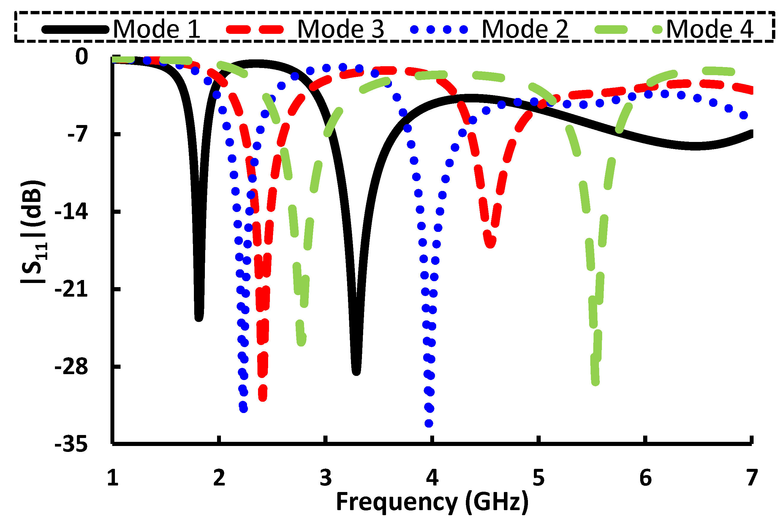
3.1. Reflection Coefficient

The reflection coefficient of the antenna was measured using a network analyzer for four operating modes of the antenna. The simulated and measured results for all operating modes of the antenna are compared in Figure 3. Figure 3a shows the reflection coefficient of the antenna when operated in Mode 1. The proposed antenna in Mode 1 operated at 1.8 and 3.3 GHz. The simulated 10-dB bandwidth of the antenna was 120 MHz (1.76–1.88 GHz) and 390 MHz (3.12–3.51 GHz) at the lower and higher resonant bands, respectively, for operating Mode 1. The measured 10-dB bandwidth for Mode 1 was recorded as 400 MHz (1.6–2 GHz) and 330 MHz (3.08–3.41 GHz) for the lower and upper operating bands, respectively. The same antenna operated at 2.25 and 3.9 GHz with different switching conditions (Mode 2). The simulated 10-dB bandwidth of 200 MHz (2.13–2.33 GHz) and 320 MHz (3.84–4.16 GHz) was quantified for lower and higher operating bands, respectively. The measured 10-dB bandwidth for Mode 2 was investigated as 300 MHz (2.05–2.35 GHz) and 420 MHz (3.78–4.2 GHz) for the lower and upper operating bands, respectively. In Mode 3, the antenna had resonant frequencies of 2.4 and 4.5 GHz with a simulated 10-dB bandwidth of 250 MHz (2.29–2.54 GHz) and 270 MHz (4.43–4.7 GHz). The measured 10-dB bandwidth for Mode 3 was recorded as 190 MHz (2.29–2.48 GHz) and 280 MHz (4.32–4.6 GHz) for the lower and upper operating bands, respectively. In Mode 4, the antenna operated at 2.78 and 5.54 GHz with a simulated 10-dB bandwidth of 310 MHz (2.63–2.94 GHz) and 320 MHz (5.37–5.69 GHz). The measured 10-dB bandwidth for Mode 4 was investigated as 350 MHz (2.6–2.95 GHz) and 360 MHz (5.35–5.71 GHz) for the lower and upper operating bands, respectively. The designed antenna can be used for different applications (GSM, 5G sub-6-GHz band, 3G Advanced/LTE, WiFi, WLAN, ISM, Bluetooth, and airport surveillance radars band) with different operating modes (Mode 1, Mode 2, Mode 3, and Mode 4).

3.2. Surface Current Distribution

The surface current distribution of each mode for their respective operating bands (Mode 1: 1.8 and 3.3 GHz, Mode 2: 2.25 and 3.9 GHz, Mode 3: 2.4 and 4.5 GHz, Mode 4: 2.78 and 5.54 GHz) is plotted in Figure 4. The surface current was distributed uniquely on the antenna surface for different operating bands. It is evident from the plots that the effective length was inversely proportional to the operating frequencies.

3.3. Gain and Efficiency

The simulated and measured antenna gains and efficiencies are presented in Figure 5. In Mode 1, the antenna’s simulated (measured) gain was >1.5 dBi (>1.45 dBi) and >1.76 dBi (>1.72 dBi) for the lower and upper operating bands, respectively. The simulated (measured) antenna’s efficiency in operating Mode 1 was >83% (>83.2%) and >82% (>82.1%) for the lower and upper bands, respectively. The simulated (measured) gain of the antenna in operating Mode 2 was >3.16 dBi (>3.14 dBi) and >3.22 dBi (>3.18 dBi) for the respective lower and upper bands. In Mode 2, the antenna’s simulated (measured) efficiency was >88% (>87.5%) and >88% (>88.1%) for the lower and upper operating bands, respectively. The simulated (measured) antenna’s efficiency in operating Mode 3 was >2.89 dBi (>2.85 dBi) and >2.75 dBi (>2.76 dBi) for the lower and upper bands, respectively. In Mode 3, the antenna’s simulated (measured) efficiency was >88% (>87.5%) and >87% (>86.6%) for the lower and upper operating bands, respectively. The simulated (measured) antenna’s efficiency in operating Mode 4 was >3.5 dBi (>3.48 dBi) and >3.79 dBi (>3.69 dBi) for the lower and upper bands, respectively. In Mode 4, the antenna’s simulated (measured) efficiency was >88.3% (>88%) and >87% (>86.2%) for the lower and upper operating bands, respectively.

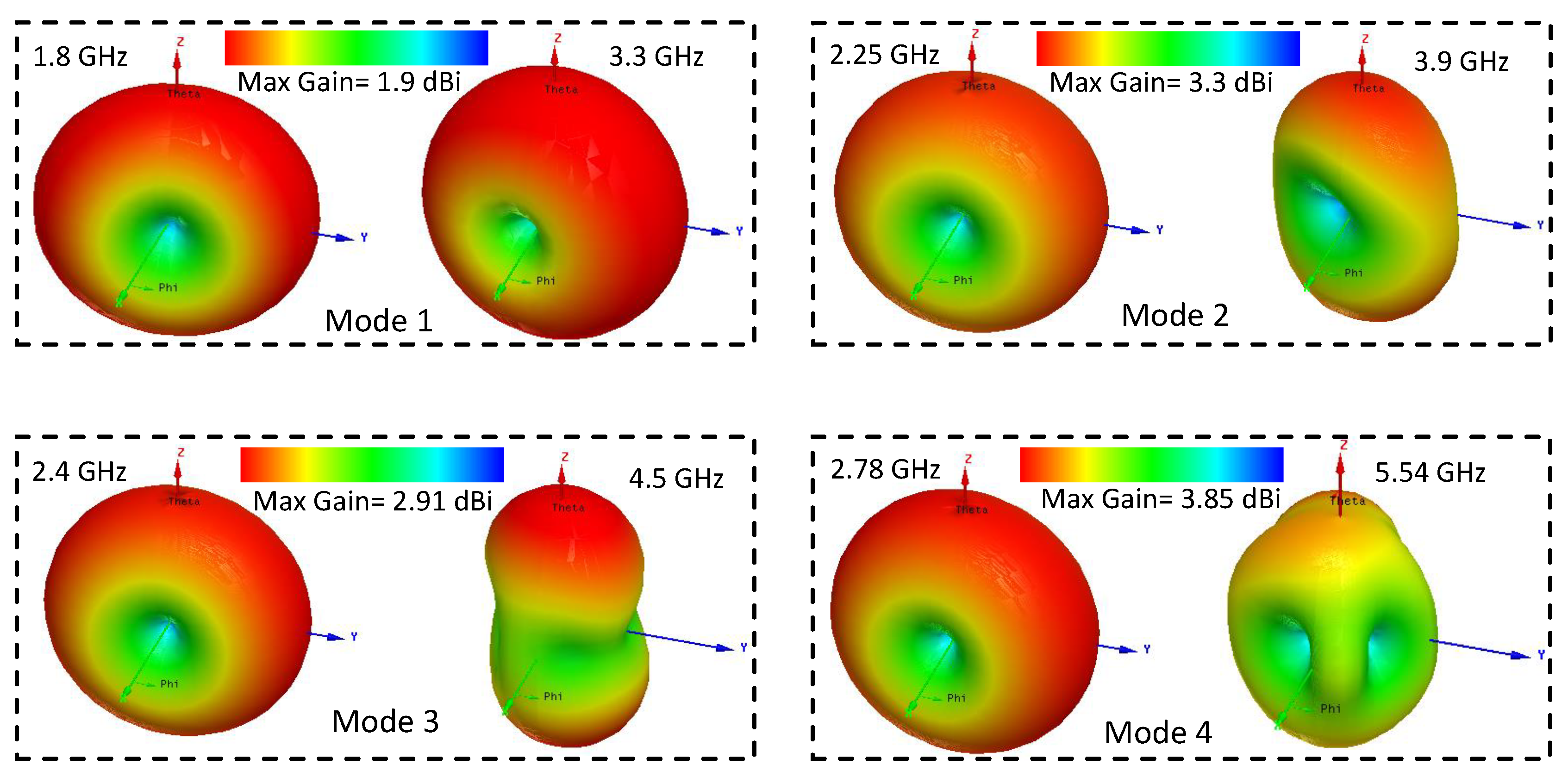
3.4. Radiation Pattern

The antenna’s radiation characteristics were analyzed using 2D and 3D radiation patterns for each resonant frequency of the four operational modes. The 2D radiation pattern of the antenna on both principal planes ( ϕ = 0 and ϕ = 90 ) was measured in an anechoic chamber. The simulated and measured 2D radiation pattern is illustrated in Figure 6. The proposed antenna had an omni-directional radiation pattern for a lower operating band at Phi = 0 in all four operating modes. At Phi = 90 , the antenna had the same radiation pattern as a figure of eight for all operating modes. For the upper operating band at Phi = 0 , the radiation pattern was omni-directional for Mode 1; however, the radiation pattern was distorted in Mode 2, Mode 3, and Mode 4. The 3D pattern of the antenna is illustrated in Figure 7.

3.5. Specific Absorption Rate Analysis

The proposed antenna covered different frequency bands such as GSM, 5G, 3G Advanced/LTE, WiFi, WLAN, ISM, and Bluetooth. The specific absorption rate (SAR) analysis was important for the proposed antenna, because most of the portable devices use these frequency bands. The SAR analysis was performed by placing the antenna on the three layers (skin, fat, and muscle) of a flat human model. The gap between the antenna and skin was kept as 4 mm. According to the International Commission of Non-Ionizing Radiation Protection (ICNIRP), the SAR value should not exceed 1.6 W/kg for one-gram and 2 W/kg for 10-gram standards [21,22]. Peak SAR values (10 grams) of 9.37, 8.99, 7.93, 5.98, 7.4, 7.11, 5.33, and 4.7 W/kg were noted for 1.8, 2.25, 2.4, 2.78, 3.3, 3.9, 4.5, and 5.54 GHz, respectively, for an input power of 1 W, as shown in Figure 8. The designed antenna exceeded the SAR limits (2 W/kg) for all operating bands using an input power of 1 W. However, many portable devices use power in the mW range [23]. Based on the above calculated SAR value, our antenna is safe if the input power is less than 213, 222, 252, 334, 270, 281, 375, and 425 mW for 1.8, 2.25, 2.4, 2.78, 3.3, 3.9, 4.5, and 5.54 GHz respectively. Hence, it is not recommended to install it directly into any portable device. An SAR reduction technique must be used before employing it in portable devices if the input power is more than the limit provided above.
An overall summary of the proposed antenna is presented in Table 2. Table 3 compares the performance of the proposed antenna with the state-of-the-art antennas. It can be noticed that the proposed antenna had smaller dimensions than the antennas presented in the literature. Furthermore, the proposed antenna used a fewer number of switches, which significantly reduce the system complexity and enhance the power efficiency. Additionally, the antenna had reasonably good gain and efficiency in all operating bands.

4. Conclusions

A low-profile (0.21 λ g × 0.35 λ g × 0.02 λ g ) and a simply-structured frequency-switchable antenna with eight frequency choices was presented in this paper. The antenna operated in four different modes depending on the ON and OFF states of the PIN diodes. In each mode, the antenna covered two unique frequencies (Mode 1 = 1.8 and 3.29 GHz, Mode 2 = 2.23 and 3.9 GHz, Mode 3 = 2.4 and 4.55 GHz, and Mode 4 = 2.78 and 5.54 GHz). The proposed antenna achieved high gain and reasonable efficiency in each mode. A fabricated model was tested experimentally to validate the simulation results. The proposed antenna can have a significant impact on compact and heterogeneous RF front-ends, because of its small geometry and efficient utilization of the frequency spectrum.

Author Contributions

Conceptualization, A.I.; methodology, A.I.; software, A.I.; validation, A.I., I.E. and A.S.; formal analysis, A.I.; investigation, A.I.; resources, L.F.A., O.A.S., S.K. and N.K.M.; data curation, A.I., N.K.M., I.E.; writing—original draft preparation, A.I.; writing—review and editing, A.I., A.S., L.F.A., I.E., O.A.S., S.K. and N.K.M.; visualization, A.I., S.K.; supervision, A.S., L.F.A., I.E., O.A.S., S.K. and N.K.M.; project administration, A.I., S.K.; funding acquisition, S.K.

Funding

Following are results of a study of the “Leaders in INdustry-university Cooperation +” Project, supported by the Ministry of Education and National Research Foundation of Korea. The authors extend their appreciation to the Deanship of Scientific Research at Majmaah University for funding this work under Project No. (RGP-2019-32).

Conflicts of Interest

The authors declare no conflicts of interest.

References

  1. Elfergani, I.; Hussaini, A.S.; Rodriguez, J.; Abd-Alhameed, R. Antenna Fundamentals for Legacy Mobile Applications and Beyond; Springer: Bolingbrook, IL, USA, 2018. [Google Scholar]
  2. Kunwar, A.; Gautam, A.K. Fork-shaped planar antenna for Bluetooth, WLAN, and WiMAX applications. Int. J. Microw. Wirel. Technol. 2017, 9, 859–864. [Google Scholar] [CrossRef]
  3. Kunwar, A.; Gautam, A.K.; Kanaujia, B.K. Inverted L-slot triple-band antenna with defected ground structure for WLAN and WiMAX applications. Int. J. Microw. Wirel. Technol. 2017, 9, 191–196. [Google Scholar] [CrossRef]
  4. Iqbal, A.; Saraereh, O.A. A compact frequency reconfigurable monopole antenna for Wi-Fi/WLAN applications. Prog. Electromagnet. Res. 2017, 68, 79–84. [Google Scholar]
  5. Iqbal, A.; Ullah, S.; Naeem, U.; Basir, A.; Ali, U. Design, fabrication and measurement of a compact, frequency reconfigurable, modified T-shape planar antenna for portable applications. J. Electr. Eng. Technol. 2017, 12, 1611–1618. [Google Scholar]
  6. Lee, S.; Sung, Y. Compact frequency reconfigurable antenna for LTE/WWAN mobile handset applications. IEEE Trans. Antennas Propag. 2015, 63, 4572–4577. [Google Scholar] [CrossRef]
  7. Ali, T.; Biradar, R.C. A compact hexagonal slot dual band frequency reconfigurable antenna for WLAN applications. Microw. Opt. Technol. Lett. 2017, 59, 958–964. [Google Scholar] [CrossRef]
  8. Ullah, S.; Hayat, S.; Umar, A.; Ali, U.; Tahir, F.A.; Flint, J.A. Design, fabrication and measurement of triple band frequency reconfigurable antennas for portable wireless communications. AEU-Int. J. Electron. Commun. 2017, 81, 236–242. [Google Scholar] [CrossRef]
  9. Khan, O.M.; Raza, K.; Shubair, R.; Islam, Q.U. Frequency Reconfigurable Implant Antenna for MICS and ISM Band Applications. In Proceedings of the 18th International Symposium on Antenna Technology and Applied Electromagnetics (ANTEM). IEEE, Waterloo, ON, Canada, 19–22 August 2018; pp. 1–2. [Google Scholar]
  10. Ruvio, G.; Ammann, M.J.; Chen, Z.N. Wideband reconfigurable rolled planar monopole antenna. IEEE Trans. Antennas Propag. 2007, 55, 1760–1767. [Google Scholar] [CrossRef]
  11. Bharathi, A.; Lakshminarayana, M.; Rao, P.S. A quad-polarization and frequency reconfigurable square ring slot loaded microstrip patch antenna for WLAN applications. AEU-Int. J. Electron. Commun. 2017, 78, 15–23. [Google Scholar] [CrossRef]
  12. Shah, S.A.A.; Khan, M.F.; Ullah, S.; Basir, A.; Ali, U.; Naeem, U. Design and Measurement of Planar Monopole Antennas for Multi-Band Wireless Applications. IETE J. Res. 2017, 63, 194–204. [Google Scholar] [CrossRef]
  13. Jin, G.P.; Deng, C.H.; Yang, J.; Xu, Y.C.; Liao, S.W. A New Differentially-Fed Frequency Reconfigurable Antenna for WLAN and Sub-6GHz 5G Applications. IEEE Access 2019. [Google Scholar] [CrossRef]
  14. Hu, P.F.; Pan, Y.M.; Zhang, X.Y.; Hu, B.J. A Filtering Patch Antenna With Reconfigurable Frequency and Bandwidth Using F-Shaped Probe. IEEE Trans. Antennas Propag. 2019, 67, 121–130. [Google Scholar] [CrossRef]
  15. Shah, I.; Hayat, S.; Basir, A.; Zada, M.; Shah, S.; Ullah, S. Design and analysis of a hexa-band frequency reconfigurable antenna for wireless communication. AEU-Int. J. Electron. Commun. 2019, 98, 80–88. [Google Scholar] [CrossRef]
  16. Ullah, S.; Ahmad, S.; Khan, B.; Ali, U.; Tahir, F.; Bashir, S. Design and Analysis of a Hexa-Band Frequency Reconfigurable Monopole Antenna. IETE J. Res. 2018, 64, 59–66. [Google Scholar] [CrossRef]
  17. Ullah, S.; Ahmad, S.; Khan, B.A.; Flint, J.A. A multi-band switchable antenna for Wi-Fi, 3G Advanced, WiMAX, and WLAN wireless applications. Int. J. Microw. Wirel. Technol. 2018, 10, 991–997. [Google Scholar] [CrossRef]
  18. Singh, A.; Goode, I.; Saavedra, C.E. A Multi-State Frequency Reconfigurable Monopole Antenna using Fluidic Channels. IEEE Antennas Wirel. Propag. Lett. 2019. [Google Scholar] [CrossRef]
  19. Balanis, C.A. Antenna Theory: Analysis and Design; John wiley & sons: Hoboken, NJ, USA, 2016. [Google Scholar]
  20. Iqbal, A.; Smida, A.; Mallat, N.K.; Ghayoula, R.; Elfergani, I.; Rodriguez, J.; Kim, S. Frequency and pattern reconfigurable antenna for emerging wireless communication systems. Electronics 2019, 8, 407. [Google Scholar] [CrossRef]
  21. Bouazizi, A.; Zaibi, G.; Iqbal, A.; Basir, A.; Samet, M.; Kachouri, A. A dual-band case-printed planar inverted-F antenna design with independent resonance control for wearable short range telemetric systems. Int. J. RF Microw. Comput.-Aided Eng. 2019, 29, e21781. [Google Scholar] [CrossRef]
  22. Basir, A.; Bouazizi, A.; Zada, M.; Iqbal, A.; Ullah, S.; Naeem, U. A dual-band implantable antenna with wide-band characteristics at MICS and ISM bands. Microw. Opt. Technol. Lett 2018, 60, 2944–2949. [Google Scholar] [CrossRef]
  23. Iqbal, A.; Basir, A.; Smida, A.; Mallat, N.K.; Elfergani, I.; Rodriguez, J.; Kim, S. Electromagnetic Bandgap Backed Millimeter-Wave MIMO Antenna for Wearable Applications. IEEE Access 2019, 7, 111135–111140. [Google Scholar] [CrossRef]
Figure 1. Geometry of the proposed antenna: (a) top view ( W 1 = 14.5 mm, L 2 = 12 mm, W 2 = 8 mm, L 3 = 12 mm, and L 1 = 25.5 mm); (b) bottom view (W = 17 mm, L = 28 mm, and L g = 2 mm); (c) side view, (d) equivalent circuit model of the PIN diode in the ON, OFF state and the biasing circuit, and (e) fabricated prototype.
Electronics 08 00976 g001
Figure 2. Reflection coefficient of the antenna for different operating modes.
Electronics 08 00976 g002
Figure 3. Simulated (Sim) and measured (Meas) reflection coefficient of the antenna: (a) Mode 1; (b) Mode 2; (c) Mode 3; and (d) Mode 4.
Electronics 08 00976 g003
Figure 4. Surface current distribution of the antenna for different operating modes.
Electronics 08 00976 g004
Figure 5. Gain and efficiency of the antenna (solid line = simulated, and dashed line = measured): (a) Mode 1; (b) Mode 2; (c) Mode 3; and (d) Mode 4.
Electronics 08 00976 g005
Figure 6. Simulated and measured radiation pattern at resonant frequencies (at Phi = 0 and at Phi = 90 ) of the antenna: (a) Mode 1; (b) Mode 2; (c) Mode 3; and (d) Mode 4.
Electronics 08 00976 g006aElectronics 08 00976 g006b
Figure 7. 3D pattern of the antenna for all operating bands.
Electronics 08 00976 g007
Figure 8. Simulated specific absorption rate (SAR) of the antenna: (a) Mode 1; (b) Mode 2; (c) Mode 3; and (d) Mode 4.
Electronics 08 00976 g008
Table 1. States of the PIN diodes for various operating modes.
D 1 D 2 D 3 Resonant Bands
Mode 1ONONON1.8 and 3.3 GHz
Mode 2ONONOFF2.25 and 3.9 GHz
Mode 3ONOFFOFF2.4 and 4.5 GHz
Mode 4OFFOFFOFF2.78 and 5.54 GHz
Table 2. Summary of the simulated antenna under different operating modes.
ParametersMode 1Mode 2Mode 3Mode 4
Frequencies (GHz)1.83.32.253.92.44.52.785.54
Bandwidth (MHz)120390200320250270310320
VSWR1.131.061.041.041.051.431.091.05
Gain (dBi)>1.5>1.76>3.16>3.22>2.89>2.75>3.5>3.79
Efficiency (%)>83>82>88>88>88>87>88.3>87
Peak SAR (W/kg)9.377.48.997.117.935.335.984.7
Table 3. Comparison of the proposed antenna with state-of-the-art reconfigurable antennas.
Ref. []Size
λ g × λ g × λ g
No. of
Switches
No. of
Bands
Operational
Bands
Gain
(dBi)
Efficiency
(%)
[4]0.62 × 0.65 × 0.021 PIN
diode
3(1.8–2.7 GHz),
(2.49–3.84 GHz),
(5.26–5.99 GHz)
NGNG
[5]0.62 × 0.65 × 0.021 PIN
Diode
3(2.06–3.14 GHz),
(2.44–3.66 GHz),
(5.11–5.66 GHz)
>1.2>90
[6]0.24 × 0.59 × 0.022 PIN
diodes
8(698–787 MHz),
(2305–2400 MHz),
(2500-2690 MHz),
(824–894 MHz),
(880–960 MHz),
(1710–1880 MHz),
(1850–1990 MHz),
(1920–2170 MHz)
0.13–1.5952.83–75.6
[7]0.21 × 0.12 × 0.022 PIN
diodes
4(2.31–2.62 GHz),
(5.13–5.32 GHz),
(2.32–2.61 GHz),
(5.12–5.33 GHz)
2.91–3.13NG
[8]0.58 × 0.88 × 0.021 PIN
diode
33.5 %, 35.72 %, and
9.94 %
1.7–3.485–90
[12]0.33 × 0.67 × 0.021 PIN
diode
436 %, 15 %, 31 %
and 22 %
1.76–2.9176.43–84.2
[13]1.68 × 1.68 × 0.092 PIN
diodes
2(2.37–2.67 GHz),
(3.39–3.62 GHz)
6.51, 7.6464.5, 69.5
[15]0.22 × 0.46 × 0.023 PIN
diodes
69.35, 13.2, 21.49,
11.71, 41.5 and
9.35%
1.85–3.4680.41–96.75
[16]0.58 × 0.67 × 0.022 PIN
diodes
6430, 1090, 1045, 2210,
1125, and 847 MHz
2.18–4.4690–97
[17]0.58 × 0.67 × 0.022 PIN
diodes
61220, 335, 512,
1020, 486, and
463 MHz
2.20–4.0192.5–97
This Work0.21 × 0.35 × 0.023 PIN diodes8(1.76–1.88 GHz),
(3.12–3.51 GHz),
(2.13–2.33 GHz),
(3.84–4.16 GHz),
(2.29–2.54 GHz),
(4.43–4.7 GHz),
(2.63–2.94 GHz),
(5.37–5.69 GHz)
1.5–3.8582–89
λ g = guided wavelength at the lower resonant frequency, NG = not given

