Article

A Fast Hybrid Beamforming Scheme for High-Speed Railway Communications

1
Key Laboratory of Universal Wireless Communications, Ministry of Education, Beijing University of Post and Telecommunications, Beijing 100876, China
2
ZTE Corporation, LTE&5G Wireless Product R&D Institute, Shenzhen 518055, China
*
Author to whom correspondence should be addressed.
Electronics 2019, 8(9), 998; https://doi.org/10.3390/electronics8090998
Submission received: 1 August 2019 / Revised: 27 August 2019 / Accepted: 2 September 2019 / Published: 6 September 2019
(This article belongs to the Special Issue Recent Advances in Multi-user MIMO Systems)

Abstract

:
With the increasingly demand for reliable mobile communication service in the high-speed railway (HSR) system, the service stability of HSR communication is of great concern in recent research. Focusing on ensuring the quality of services (QoS) and system throughput, massive multi-input multi-output (massive MIMO) and beamforming technologies have been widely applied. In this paper, aiming to minimize the communication outage probability (OP) and not to decrease spectrum efficiency (SE) too much, we propose a fast HBF (F-HBF) scheme for HSR communications. The proposed scheme uses a low-complexity beam-searching algorithm to trace high-speed trains in real time. The simulation results verify that the proposed scheme can significantly reduce OP without too much SE degradation.

1. Introduction

With the rapid development of high-speed railway (HSR), an increasing number of people prefer to travel by this ground vehicle. Therefore, HSR is becoming an emergent wireless communication scenario with development potential [1]. The fifth-generation (5G) mobile communication system is devoted to providing reliable communication services for high-speed trains with speeds up to 500 km/h [2]. However, due to high-speed movement of user terminals, the reciprocity of the uplink and downlink channels exist only for a limited time, which brings great challenge to the wireless communication system. The reliability and real-time performance of the data transmission cannot be guaranteed in the HSR scenario when using traditional communication technology. This forced us to make some changes to meet the passengers’ communication requirements on the HSR.
There are some studies committed to address the unique problems in the HSR scenario at sub-6 GHz spectrum. The handover (HO) probability is a key factor which influences the QoS in HSR communication system. The authors in [3] proposed an effective scheme to deal with the handover process on the distributed antenna system, and used an antenna selected scheme with power allocation algorithm to reduce the handover failure probability. On another aspect, the cell coverage is also an important part of the HSR dedicated communication network. A closed form expression of the cell coverage was first derived by the authors of [4], and it turned out that the linear coverage of HSR was found to be bigger than the traditional circular coverage.
Compared with the sub-6 GHz spectrum, millimeter wave (mmWave) band has large amount of bandwidth which can offer sufficient resources for high-quality and real-time data transmission. Please note that there only exists LOS component in the HSR scenario since lack of scatterers near the viaduct [5]. Therefore, mmWave is naturally suitable for this scenario considering these inherent qualities. Yet the defects of mmWave cannot be neglected. Due to the highly absorptive of atmosphere, the path loss caused during mmWave propagation is relatively large, leading to serious signal attenuation [6]. According to Friss transmission equation, the received signal strength will be reduced because of the small antenna cross section at shorter wavelength. Consequently, massive multiple-input multiple-output (massive MIMO) has been expected as a key component to guarantee the efficiency of data transmission and the quality of service (QoS) for user. To obtain larger antenna gain, beamforming technology is adopted to improve the performance of mmWave communication system.
Full digital beamforming is first proposed to realize massive MIMO; however, it will bring high hardware cost in implementation. Therefore, hybrid beamforming (HBF) architecture is becoming an efficient transceiver to transmit massive data flow [7]. Generally, HBF techniques can be divided into two steps, i.e., digital beamforming (DBF) and analog beamforming (ABF) [8,9]. Considering the realization complexity, the codebook-based low-cost beam-searching algorithm for mmWave seems to be more acceptable to ensure the QoS in HSR scenario.
The beam-searching algorithm, which is one class of the beamforming algorithm based on beam codebook, has been studied extensively in the literature for different communication scenarios. A fast beam search algorithm based on Powell algorithm has been proposed by [10], the algorithm abstracts beam switching as a global optimization problem on a two-dimensional plane which is made of the indexes of codebook. This algorithm can greatly decrease the beam-searching complexity and ensure the searching accuracy. The authors in [11] proposed a beamforming protocol based on media access control (MAC) layer to decrease the beam-searching latency while minimizing the path loss of 60 GHz wireless personal area networks (WPAN) systems. In [12], a beam alignment technique has been proposed based on adaptive subspace sampling and hierarchical beam codebooks, aiming to overcome the outdoor impairments in millimeter wave propagation.
In general, most studies on HSR scenario focus on the handover (HO) techniques between base stations (BSs), while ignoring beam switching techniques within BS. Although the former (HO between BSs) can make sure the most QoS of users on board, the latter can decrease the probability of beam misalignment, and reduce the outage probability. Moreover, beam switching within BS also ensure a smoother switching between BSs. The authors in [13] proposed a timer-based beam selection algorithm for HSR. The algorithm used the prior knowledge of train position and direction in railway environment to estimate the angle of arrival and departure of propagation path. Then the optimal beam pairs can be calculated. This algorithm can be used at beam switching within BS and can achieve a close performance to the optimal single value decomposition (SVD) scheme. However, this algorithm relies on the prior knowledge of train position and needs extra cost to deal with velocity feedback.
Aiming to overcome the high OP brought by beam misalignment during the high-speed movement, we proposed a F-HBF scheme to deal with the beam misalignment problem in HSR scenario. The proposed scheme is a combination of fast analog beam-searching and digital beamforming algorithms. In contrast to [13], F-HBF does not need velocity feedback to calculate optimal beam pairs, but uses the improved fast beam-searching algorithm to carry on the periodic omni-directional search.
Our contribution is to derive the upper bound of OP and to use it to improve beam-searching algorithm. Moreover, we study the influence of periodic beam switching and consider that a proper beam-searching time interval can balance the searching cost and OP. The simulation results show that periodic beam switching can decrease OP compared with no periodic beam switching scheme. Moreover, the shorter of the beam-searching time interval can lead the lower of OP within the same BS.
Notation: X , x and x represent the matrix, vector, and scalar, respectively. ( * ) T , ( * ) H , ( * ) 1 , and * denote the transport, conjugate transport, inverse, and determinant value, respectively. d i a g ( , , ) denotes diagonal matrix formed by •, and • can be scalar, vector, or matrix. N i means the set of beam pair numbers at ith iteration.
The remainder of the paper is organized as follow: Section 2 describes the system and mmWave channel models. Section 3 proposes F-HBF scheme to cope with the beam misalignment challenge in HSR scenario. Section 4 presents the simulation results of the proposed scheme, and compares with those of the conventional HBF algorithm. Finally, concluding remarks are drawn in Section 5.

2. System Model

HBF plays a key role in massive MIMO system. The structure of HBF can be divided into two types, i.e., fully connected and partially connected HBF [14,15,16]. In full-connection HBF, each RF chain is connected to every antenna element, so that transceiver can jointly optimize all the antenna units and have a finer beam with full beamforming gains. However, the computational complexity is higher than the other structure. In partially connected HBF, each RF chain is connected to a sub-array of the antennas. Therefore, this structure has lower hardware complexity than its fully connected counterpart, while the array gain is lower, and the beam width is rougher obviously. Consequently, this paper chooses partially connected HBF which aims to decrease the computational complexity to achieve fast HBF.
Considering the HSR scenario shown in 
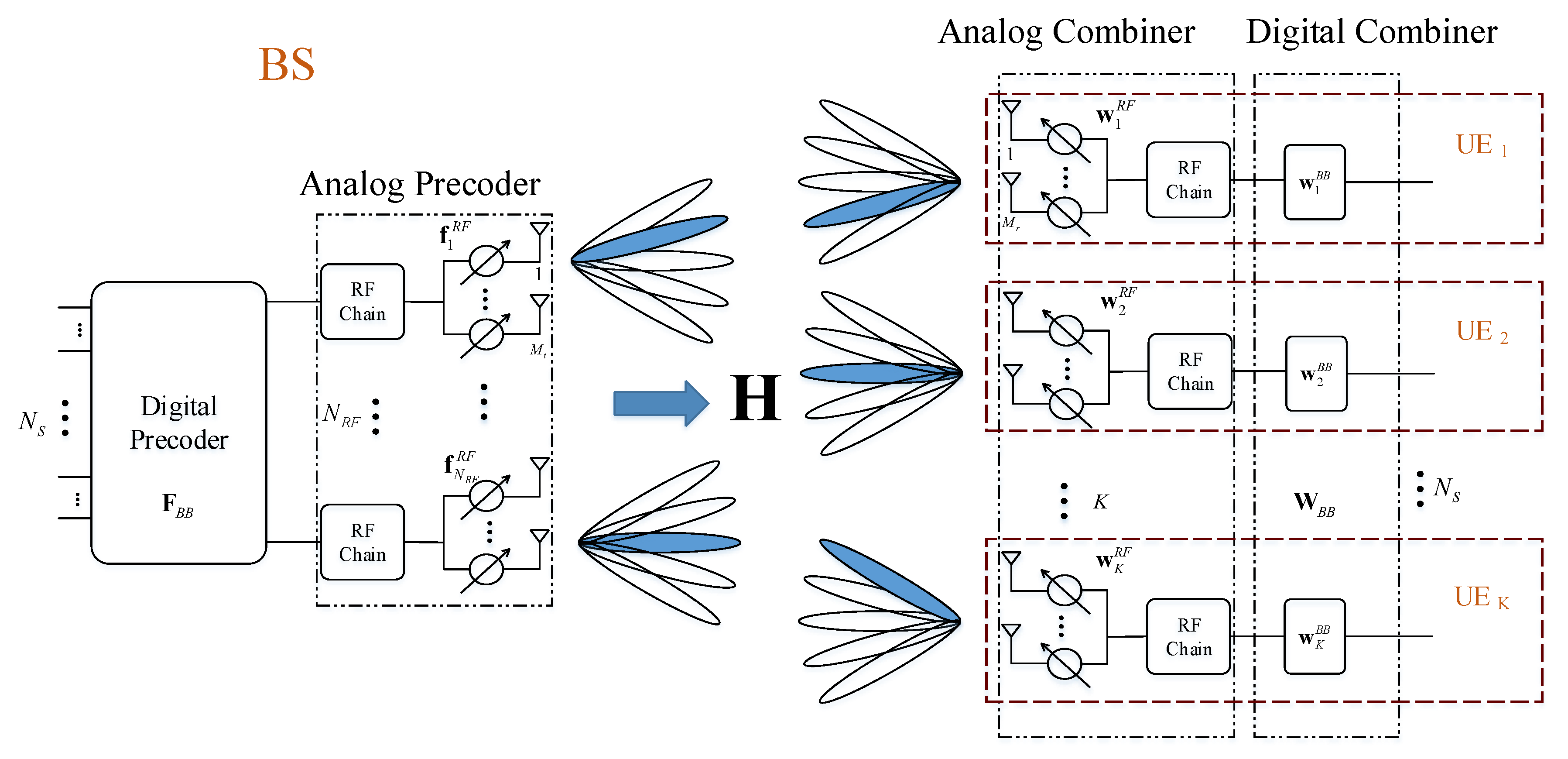
Figure 1, the base stations are deployed along the rail track, and each BS has the directional beam pointing to the relay of the high-speed railway. To simplify the research model without losing generality, a multi-user mmWave MIMO system is adopted in our research. As mentioned above, we consider the MU-MIMO system with partially connected HBF. It is shown in Figure 2 that each BS serves K users. Each BS and user equipment (UE) is equipped with N R F and 1 RF chains, respectively. Each RF chain at BS side connects an antenna sub-array with M t antenna elements and the RF chain at UE side connects with M r antenna elements. Therefore, the total numbers of antennas are N T = N R F M t and N R = K M r for BS and K UEs, respectively. N s is the number of data streams. For simplicity, we consider N s = N R F = K in our research.
The N s data streams are first processed by baseband precoder F B B ( N R F × N s ) at transmitter side. Then the data streams are handled by the analog precoder f n r f R F ( M t × 1 ), where n r f = 1 , , N R F . Analog precoder is made by finite phase shifters, which means the phase shift resolution is limited. Then the transmission signal is shown as
x = F R F F B B s ,
where s is the signal with size N s × 1 , and E s s H = P s N s I N s , P s is the total transmit power. F R F is analog precoder matrix with size N R F M t × N R F written as
F R F = f 1 R F 0 0 0 f 2 R F 0 0 0 f N R F R F N R F M t × N R F ,
where F R F F B B F 2 = N s . Then the total received signal of K UEs is expressed as
y = H F R F F B B s + n ,
where y is received vector with size K M r × 1 , H is channel matrix with size N R × N T , and is block diagonal matrix with K sub-channels, i.e., H = d i a g H 1 , , H K . n is a Gaussian distribution noise vector with C N 0 , σ n 2 . Then the received signal must first be processed by analog combiner w n r f R F ( n r f = 1 , , K ) at each UE side, where w n r f R F 2 = 1 M r . By using digital combiner W B B , the final signal is written as
y ˜ = W B B H W R F H H F R F F B B s + W B B H W R F H n ,
where W R F is analog combiner matrix with size K M r × K , and is shown as
W R F = w 1 R F 0 0 0 w 2 R F 0 0 0 w K R F K M r × K .
The received signal at each UE connects with only one RF chain, then the digital combiner matrix W B B becomes a diagonal matrix as W B B = d i a g w 1 B B , , w K B B . According to Equation (4) and Shannon formula, the achievable rate can be expressed as
R = log 2 I N s + P s N s W H B H H F H B F H B H H H W H B σ n 2 W H B W H B H ,
where W H B = W R F W B B , F H B = F R F F B B .

Channel Model

Considering the sparsity of mmWave and the antenna array correlation, the mmWave channel for the kth UE usually be expressed as
H k = M r M t ρ l = 1 L α k , l Λ r ϕ k , l r , θ k , l r Λ t ϕ k , l t , θ k , l t a k , r ϕ k , l r , θ k , l r a k , t ϕ k , l t , θ k , l t H exp j 2 π v l t ,
where ρ means channel path loss factor, L is number of channel path, α k , l is the lth channel path gain of the kth UE and obey a Gaussian distribution α k , l C N 0 , P ¯ R , l = 1 , 2 , , L , P ¯ R denotes the average power gain. ϕ l t θ l t and ϕ k , l r θ k , l r represent the azimuth (elevation) of arrival and departure of corresponding channel path. Λ r ϕ k , l r , θ k , l r and Λ t ϕ k , l t , θ k , l t denote the antenna gains at the corresponding angle of arrival and angle of departure. For simplicity, Λ r ϕ k , l r , θ k , l r and Λ t ϕ k , l t , θ k , l t can be set to 1. a t ϕ k , l t , θ k , l t are antenna array response vectors on transmit side with size C M t × 1 and a r ϕ k , l r , θ k , l r is the counterpart on receiver side. The antenna array response vectors can be expressed as
a ϕ , θ = 1 , , e j π m x 1 cos ϕ sin θ + m y 1 sin ϕ sin θ , , e j π M x 1 cos ϕ sin θ + M y 1 sin ϕ sin θ ,
where m x and m y are the antenna index along the x and y axes, and the total antenna elements are M x and M y . Doppler shift is denoted by the last part of channel H k , evaluated with the parameter
v l = r r , l T v ¯ λ ,
where r r , l is the spherical unit vector with azimuth of arrival ϕ l r and elevation of arrival θ l r , given by
r r , l = sin θ l r cos ϕ l r sin θ l r sin ϕ l r cos θ l r .
v ¯ denotes the UE velocity vector and expressed by v ¯ = v · sin θ v cos ϕ v sin θ v sin ϕ v cos θ v T , where v is the UE velocity, ϕ v and θ v means travel azimuth angle and elevation angle, respectively.

3. Problem Model

In this section, we establish the problem model of F-HBF in HSR scenario. The problem model aims to reduce the outage probability during the high-speed movement process while ensuring the QoS of UE. Then the F-HBF algorithm is proposed to achieve the optimal solution.

3.1. Received Signal Strength

As our research focuses on the high-speed railway scenario with F-HBF, the received signal strength (RSS) is one of key factors to be considered. The RSS is usually considered in dBm unit. Then
P r e c e i v e = 10 log 10 P r ,
where P r e c e i v e is the RSS in dBm unit, and P r is the RSS in mW unit. For an OFDM system, the inter-carrier interference (ICI) caused by Doppler frequency shift is the primary interference. Consequently, the RSS with ICI and normalized noise power at the mth time interval can be expressed as
P r e c e i v e m = 10 log 10 P r P r η + 1 ,
where η = 1 1 1 x 1 J 0 2 π f d T s x d x denotes the zeroth-order Bessel function of the first kind, f d means the maximum Doppler frequency shift, and T s represents the symbol duration.

3.2. Outage Probability

To evaluate the system performance of the proposed F-HBF scheme, link outage probability P o u t is introduced as the performance metric. As mentioned in [3,4], the link outage appears when the RSS at user side is smaller than the minimum communication threshold T. Therefore, P o u t represents the probability that RSS is smaller than threshold T. In another word, the smaller the P o u t is, the better performance of the proposed scheme can achieve. Then the outage probability at mth time interval can be expressed as
P o u t m = P P r e c e i v e m < T = 1 Q T P ¯ r e c e i v e σ = 1 2 1 2 · e r f M σ 2 ,
where G = P ¯ r e c e i v e T , σ denotes the standard deviation of the normally distributed shadow fading. The Taylor expression of error function e r f x can be written as
e r f x = 2 π n = 0 1 n x 2 n + 1 n ! 2 n + 1 .
When n 2 , the higher-order infinitesimal component of (14) can be ignored and (14) can be rewritten as
e r f x = 2 π x x 3 3 + O x 5 2 π x x 3 3 .
Then the outage probability has the upper bound that
P o u t m = 1 2 1 2 e r f G σ 2 1 2 1 π G σ 2 1 3 · G σ 2 3 = P o u t , u p m .

3.3. F-HBF Algorithm

It is shown that a joint transmitter-receiver HBF design problem is usually difficult to deal with [8,17]. Therefore, researchers usually focus on the two-step HBF design algorithm [8,18,19]. Most two-step HBF design algorithms need to assume the analog matrix F R F is fixed to find the optimal digital matrix F B B . Furthermore, the analog matrix F R F can be achieved by using the optimal F B B with iterative algorithm. However, it costs time to achieve the HBF matrix in HSR scenario. Consequently, we proposed a low-complexity F-HBF scheme to overcome this problem. Aiming to find the optimal HBF precoder and combiner matrices at both transmitter and receiver sides, the problem can be formed as follows,
max F B B F R F W B B W R F R s . t . T r F R F F B B F B B H F R F H 1 F R F i , j 2 = 1 , i , j W R F i , j 2 = 1 , i , j .
To simplify the algorithm complexity, we divided the problem into two sub-problems, which are shown in the next two sub-parts. The analog combiner and precoder are decided by fast beam-searching algorithm. Then the digital combiner and precoder are computed by a heuristic algorithm.

3.3.1. Analog Beam-Searching Algorithm

Due to the low-complexity and transmission energy consumption during beam-searching process, the ISWR-P beam-searching algorithm has been widely applied in [10,20,21,22]. However, this algorithm can only locate one beam pair during the beam-searching process, which represents low efficiency during the multi-beam-searching process at BS side. Consequently, we extend the beam-searching algorithm from one beam pair to multi-beam pairs in this paper to fit the multi-user HSR scenario. Meanwhile, the objective function of the optimal problem should be modified.
According to Equations (6) and (17), the communication QoS should be first maintained by SE and outage probability. Therefore, the main purpose is to find the optimal beam pairs to maximize the SE and meanwhile keep the theoretical outage probability smaller than the upper bound of outage probability. For the fixed digital precoder and combiner, the objective function of analog sub-problem can be written as
max W R F , F R F R = log 2 I N s + P r σ n 2 W H B F W H B F H s . t . P o u t m P o u t , u p m W R F i , j 2 = 1 , i , j F R F i , j 2 = 1 , i , j ,
where P ¯ r = P s N s W H B H H F H B 2 . Obviously, the minimization of OP is the most important part in HSR scenario. Therefore, combining with (16), we minimize the upper bound of OP by solving
min P o u t , u p m = 1 2 1 π G σ 2 1 3 · G σ 2 3 .
According to the objective function, it can obtain optimal value when G = ± 2 σ , and also because of G = P ¯ r e c e i v e T , then G should be positive. Then we get,
P ¯ r e c e i v e T = 2 σ .
As average RSS P ¯ r e c e i v e and minimum communication threshold T can be considered in dBm unit, then expression (20) means average RSS should be bigger than threshold in scale 2 σ dB . Then combining with (20), expression (18) can be transformed into
p o p t , q o p t = arg min p , q P ¯ r e c e i v e T + 2 σ = arg min p , q 10 log 10 P ¯ r P ¯ r η + 1 T + 2 σ s . t . P ¯ r = P s N s W H B H H F H B 2 η = 1 1 1 x 1 J 0 2 π f d T s x d x .
Which means to choose the optimal beam pairs to let the average RSS approach 2 σ + T dBm. In this way, the upper bound of outage probability can be minimum which can maintain the QoS of HSR scenario.
Then the beam-searching algorithm for HSR scenario based on ISWR-P [10] with improved objective function will be further elaborated in the following paragraphs.
The beam-searching algorithm is based on beam codebook, which can be defined by an M × N matrix F . M denotes the number of antennas and N is the number of beams. Each column of F expresses the phase rotation of every antenna, which can generate a specific beam pattern. If we represent the beam index by the number of columns, then the beam pair indexes on both transmitting and receiving sides can form a two-dimensional integer set p , q N .
The beam-searching algorithm is constituted with two parts, 2-D plane searching and refinement searching. First, the algorithm needs the kth UE’s initial main lobe direction φ 0 , ψ 0 k , which can be arbitrary direction. The number of working antennas is initialized to 2. Then find the closest beam pair index p 0 ( 1 ) , q 0 ( 1 ) k during the index set N 1 , where N 1 is formed with the column number of the beam codebook when the number of antennas is 2. Initial searching direction is d = 0 , 1 . Then we proceed to do a point-to-point search in the direction d from the initial point p 0 ( 1 ) , q 0 ( 1 ) k . If the searching point is out of the set N 1 , then let d = d . As we can see, there are only three main searching directions d = 0 , 1 , d = 1 , 1 , d = 1 , 0 and three inverse directions d = d . Consequently, we can change the searching directions to find the optimal point x j , k ( i ) = p j ( i ) , q j ( i ) k which can maximize the objective function (18).
Secondly, the refinement searching starts. With the optimal point x j , k ( i ) = p j ( i ) , q j ( i ) k found in first part, the initial main lobe direction can be updated with φ i , ψ i k . Then the working antennas will increase during each iteration from 2 i , i = 2 , 3 , 4 to M t or M r . It should be noted that the case i = 1 has been proceeded in the 2-D plane searching part. In each iteration, we first find the nearest point p 0 ( i ) , q 0 ( i ) k according to the new main lobe φ i 1 , ψ i 1 k , then let it be the searching center. There only 8 points around the searching center point should be checked by (18). It is because that the optimal point p 0 ( i ) , q 0 ( i ) k will be just around the optimal point from previous iteration p 0 ( i 1 ) , q 0 ( i 1 ) k according to [10]. Then update the main lobe direction φ i , ψ i k by using point p 0 ( i ) , q 0 ( i ) k . By finishing the iteration, we achieve the optimal analog precoder and combiner f ^ k q o p t and w ^ k p o p t . By using Equations (2) and (5) the total analog precoder and combiner are formed as
F R F = d i a g f ^ 1 q o p t , , f ^ K q o p t , W R F = d i a g w ^ 1 q o p t , , w ^ K q o p t .
The pseudo-code is shown in Algorithm 1.

3.3.2. Digital Precoder and Combiner Algorithm

With the analog precoder and combiner achieved from above subsection, the digital parts will be derived in this subsection. The objective function (18) can be rewritten as
max W B B , F B B R = log 2 I N s + P s N s W B B H H e q F B B 2 σ n 2 W B B H W B B s . t . P o u t m P o u t , u p m ,
where H e q = W R F H H F R F and W R F H W R F = I N t . Then the optimal digital precoder F ^ B B can be designed by zero-forcing (ZF) which performs well in MIMO systems [23,24]. F ^ B B should be expressed as
F ^ B B = H e q H H e q H e q H 1 .
Then the normalized result of F ^ B B is
F ^ B B = F ^ B B F ^ R F F ^ B B .
With the optimal digital precoder F ^ B B , the objective function (23) is equivalent to maximize the received signal to noise ratio (SNR)
max W B B SNR r = P s N s W B B H H e q F ^ B B F ^ B B H H e q H W B B σ n 2 W B B H W B B s . t . P o u t m P o u t , u p m .
Algorithm 1 Beam-searching algorithm
Require: 
Initial main lobe direction φ 0 , ψ 0 k , number of searching rounds m, number of antennas at transmitting and receiving sides M t , M r , initial 2-D plane searching direction d, refinement counter i = 0 , 2-D searching counter j = 0 .
Ensure: 
p o p t , q o p t k
1:
% Part I — 2-D plane searching
2:
Set i = 1 , the number of working antennas equals 2 on both sides and the beam pair index set N 1 . Find the nearest beam pair index x 0 ( 1 ) = p 0 ( 1 ) , q 0 ( 1 ) based on the initial main lobe direction φ 0 , ψ 0 k , and let x 0 ( i ) be the initial point of 2-D plane searching. The searching direction d.
3:
for each j [ 0 , 3 ] do
4:
 % Searching direction d only has 3 direction to change
5:
for each x j , k ( i ) N 1 do
6:
   x j , k ( i ) = x j , k ( i ) + d
7:
  if x j , k ( i ) N 1 then
8:
   Let d = d , x j , k ( i ) = x j , k ( i ) + d .
9:
  end if
10:
  Calculate (21), find the optimal point x j + 1 , k ( i )
11:
end for
12:
 Let d = d × cos π π 4 4 sin π π 4 4 sin π π 4 4 cos π π 4 4
13:
end for
14:
% Part II — Refinement searching
15:
Update the main lobe direction φ i , ψ i k with the optimal point x j + 1 , k ( i ) from Part I.
16:
Set the searching step index in every refinement search
Λ = [ ( 1 , 1 ) ; ( 1 , 0 ) ; ( 1 , 1 ) ; ( 0 , 1 ) ; ( 0 , 1 ) ; ( 1 , 1 ) ; ( 1 , 0 ) ; ( 1 , 1 ) ] .
17:
for each i [ 2 , m ] do
18:
 Set the working antennas on both sides min 2 i , M t , min 2 i , M r . Update the beam pair index set N i . According to the main lobe direction φ i 1 , ψ i 1 k , find the nearest beam pair p 0 i , q 0 i k .
19:
 Set the point x k ( i ) = p 0 i , q 0 i k be the initial searching point.
20:
for i n d e x [ 1 , 8 ] do
21:
  % 8 point around the searching point
22:
  Let x k ( i ) = x k ( i ) + Λ ( i n d e x ) .
23:
  if x k ( i ) N i then
24:
   Skip this round circulation.
25:
  end if
26:
  Calculate (21), find the optimal point x k , o p t = p o p t , q o p t k = x k ( i )
27:
end for
28:
end for
29:
Out put the kth UE’s optimal beam pair p o p t , q o p t k .
Let matrix A = H e q F ^ B B F ^ B B H H e q H , and A C N R F × N R F is a Hermitian matrix. Consequently, (26) can be formed as a Rayleigh-Ritz expression
SNR r = P s N s σ n 2 W B B H A W B B W B B H W B B .
Then the optimal W ^ B B is the corresponding eigenvector of the largest eigenvalue of A , i.e., A W ^ B B = λ max W ^ B B .

3.4. Complexity Analysis

In this subsection, the complexity analysis of Algorithms 1 and 2 will be provided. The complexity in the proposed algorithm has two parts: the beam-searching complexity and computation complexity.
The beam-searching complexity in Algorithm 1 is O k log N , where k is the number of searching points during every iteration of refinement searching and N is the number of antennas.
The computation complexity in Algorithm 2 is shown below. As a premise to analysis the complexity of matrix computation, we should explain some commonly used complexity. The complexity of eigenvalue decomposition and pseudo-inverse of a matrix with size of M × N is O min M 2 N , M N 2 ([25,26]). Consequently, line 2 and line 4 in Algorithm 2 contain matrix inverse and eigenvalue decomposition with complexity O N R F 3 . Then, the overall complexity of Algorithm 2 is O N R F 3 .
Algorithm 2 Digital beamforming matrix algorithm
Require: 
Analog precoder F ^ R F and combiner W ^ R F from Algorithm 1, wireless channel H
Ensure: 
F ^ B B , W ^ B B
1:
Calculate equivalent channel H e q = W R F H H F R F .
2:
Calculate optimal digital precoder F ^ B B by using (24), (25).
3:
Calculate Hermitian matrix A = H e q F ^ B B F ^ B B H H e q H .
4:
Calculate the eigenvalues of A , i.e., A x = λ x , and find the corresponding eigenvector x max of the largest eigenvalue λ max of A .
5:
Let W ^ B B = x max .

4. Simulation Results

In this section, the simulation results are presented to demonstrate the performance of the proposed F-HBF scheme for MU-MIMO systems. At BS side, each antenna sub-array serves one carriage of a high-speed train, and the number of antennas in each sub-array is M t = 8 . The receive antennas at UE side is M r = 4 . The standard deviation of normally distributed shadow fading is δ = 8 dB. The carrier frequency is 60 GHz and the velocity of high-speed train is v = 100 m/s. There are usually two relative motion patterns between HST and BS, i.e., moving to BS (MTB) and moving off BS (MOB). There may has the third motion pattern, move around BS. However, the motion radius usually very large for HST to keep the carriages stable. Therefore, this pattern can be approximately regarded as first two patterns.
Figure 3a indicates the effect of different beam-searching time intervals on the outage probability. In this case, we consider K = 3 carriages of an HST with the length of each carriage is 25 m, and SNR = 10 dB. The location relationship between HST and BS is shown in Figure 3b and the motion pattern is MTB. The initial position of HST shown in Figure 3b is 25 3 , 25 , and the distance between HST and BS is 50 m. The travelling direction is −2/3π. Moreover, the total OP of 3 carriages is defined as P o u t = 1 k = 1 K 1 P o u t , k . As we can see, with the growth of beam-searching time interval Δ t from 2 ms to 200 ms, the OP of 3 carriages also increase. Moreover, when Δ t growths from 2 ms to 80 ms, the OPs do not increase very much at the same time point, i.e., OPs increase from 0.3 to 0.4 at 0.8 s. However, for Δ t = 200 ms, the OP increase to 0.52 at 0.8 s. Consequently, even though the shorter the time interval can achieve better OP, it also brings higher beam-searching cost.
Figure 4a depicts the effect of periodic beam-searching on OP. The solid line and the dotted line indicate the with and without periodic beam-searching, respectively. As can be observed from the figure, the solid line outstrips the dotted line in the sense of OP. It can be observed from Figure 4a that the solid line indicates HST is in MTB pattern before 0.4 s and is in MOB pattern after 0.4 s. However, the dotted line reaches 100 % outage at around 0.38 s and 0.6 s. Because the initial beam pair does not change during the motion, and HST experience null beam at these two locations observed from Figure 4b.
Figure 5 shows the comparison of the proposed scheme with full digital beamforming and algorithms in [8,13,18] in terms of SE. The solid, star, rhombus, triangle, and square lines indicate the performances of full digital beamforming, the proposed F-HBF scheme, the compared HBF algorithms in [8,13,18], respectively. As can be observed from the figure, the proposed F-HBF scheme performs very close to the full digital beamforming. The HBF algorithm in [8,13,18] performance close to full digital beamforming and proposed algorithm at low SNRs, while the HBF algorithm in [8,13] has almost 5 dB gap compared with the full DBF when SNR increases. The algorithm in [13] only have ABF part, so we complement the DBF part. Therefore, the SE increases accordingly. Moreover, the gap of algorithm in [18] grows even larger when SNR is higher than 5 dB. This is because the algorithm uses greedy algorithm to achieve the analog beamforming vectors which will be worse than the other algorithm at higher SNRs.

5. Conclusions

In this paper, a fast HBF scheme has been proposed to deal with the beam misalignment problem and high QoS requirement in HSR scenario. In the proposed scheme, the upper bound of outage probability has been derived and used in the objective function during beam-searching process, which can improve the communication stability to ensure QoS. The simulation results also show that a proper beam switch time can improve the outage probability performance. Moreover, simulation results verify that the performance of proposed F-HBF scheme is closer to that of full digital beamforming compared with other algorithms.

Author Contributions

Conceptualization, Y.X.; Data curation, Y.X. and Y.W.; Formal analysis, Y.X. and Y.W.; Funding acquisition, G.Q.; Methodology, Y.W.; Software, Y.X.; Writing – original draft, Y.X. Writing – review & editing, Y.W. and Y.X.

Funding

This work was supported by the National Key Technology Research and Development Program of China under grant no. 2018ZX03001002-004.

Conflicts of Interest

The authors declare no conflict of interest.

References

  1. Ai, B.; Cheng, X.; Kürner, T.; Zhong, Z.; Guan, K.; He, R.; Xiong, L.; Matolak, D.W.; Michelson, D.G.; Briso-Rodriguez, C. Challenges Toward Wireless Communications for High-Speed Railway. IEEE Trans. Intell. Transp. Syst. 2014, 15, 2143–2158. [Google Scholar] [CrossRef]
  2. Guan, K.; Ai, B.; Peng, B.; He, D.; Li, G.; Yang, J.; Zhong, Z.; Kürner, T. Towards Realistic High-Speed Train Channels at 5G Millimeter-Wave Band—Part I: Paradigm, Significance Analysis, and Scenario Reconstruction. IEEE Trans. Veh. Technol. 2018, 67, 9112–9128. [Google Scholar] [CrossRef]
  3. Liu, Z.; Fan, P. An Effective Handover Scheme Based on Antenna Selection in Ground–Train Distributed Antenna Systems. IEEE Trans. Veh. Technol. 2014, 63, 3342–3350. [Google Scholar] [CrossRef]
  4. Ai, B.; He, R.; Li, G.; Guan, K.; He, D.; Shi, G.; Zhong, Z. Determination of Cell Coverage Area and its Applications in High-Speed Railway Environments. IEEE Trans. Veh. Technol. 2017, 66, 3515–3525. [Google Scholar] [CrossRef]
  5. Guan, K.; Ai, B.; Peng, B.; He, D.; Li, G.; Yang, J.; Zhong, Z.; Kürner, T. Towards Realistic High-Speed Train Channels at 5G Millimeter-Wave Band—Part II: Case Study for Paradigm Implementation. IEEE Trans. Veh. Technol. 2018, 67, 9129–9144. [Google Scholar] [CrossRef]
  6. Rappaport, T.S.; Xing, Y.; MacCartney, G.R.; Molisch, A.F.; Mellios, E.; Zhang, J. Overview of Millimeter Wave Communications for Fifth-Generation (5G) Wireless Networks—With a Focus on Propagation Models. IEEE Trans. Antennas Propag. 2017, 65, 6213–6230. [Google Scholar] [CrossRef]
  7. Park, S.; Alkhateeb, A.; Heath, R.W. Dynamic Subarrays for Hybrid Precoding in Wideband mmWave MIMO Systems. IEEE Trans. Wirel. Commun. 2017, 16, 2907–2920. [Google Scholar] [CrossRef]
  8. Sohrabi, F.; Yu, W. Hybrid digital and analog beamforming design for large-scale antenna arrays. IEEE J. Sel. Top. Signal Process. 2016, 10, 501–513. [Google Scholar] [CrossRef]
  9. Bogale, T.E.; Le, L.B. Beamforming for multiuser massive MIMO systems: Digital versus hybrid analog-digital. In Proceedings of the 2014 IEEE Global Communications Conference, Austin, TX, USA, 8–12 December 2014; pp. 4066–4071. [Google Scholar]
  10. Zou, W.X.; Du, G.L.; Li, B.; Zhou, Z. Step-Wisely Refinement Based Beam Searching Scheme for 60 GHz Communications. Wirel. Pers. Commun. 2013, 71, 2993–3010. [Google Scholar] [CrossRef]
  11. Wang, J.; Lan, Z.; Pyo, C.W.; Baykas, T.; Sum, C.S.; Rahman, M.A.; Funada, R.; Kojima, F.; Lakkis, I.; Harada, H.; et al. Beam codebook based beamforming protocol for multi-Gbps millimeter-wave WPAN systems. IEEE J. Sel. Areas Commun. 2009, 27, 1390–13999. [Google Scholar] [CrossRef]
  12. Hur, S.; Kim, T.; Love, D.J.; Krogmeier, J.V.; Thomas, T.A.; Ghosh, A. Millimeter Wave Beamforming for Wireless Backhaul and Access in Small Cell Networks. IEEE Trans. Commun. 2013, 61, 4391–4403. [Google Scholar] [CrossRef] [Green Version]
  13. Laiyemo, A.O.; Luoto, P.; Pirinen, P.; Latva-Aho, M. Higher frequency band beamforming scheme for high speed train. In Proceedings of the 2017 IEEE Vehicular Networking Conference (VNC), Torino, Italy, 27–29 November 2017; pp. 203–208. [Google Scholar]
  14. Xiao, Y.; Wang, Y.; Xiang, W. Dimension-Deficient Channel Estimation of Hybrid Beamforming Based on Compressive Sensing. IEEE Access 2019, 7, 13791–13798. [Google Scholar] [CrossRef]
  15. Molisch, A.F.; Ratnam, V.V.; Han, S.; Li, Z.; Nguyen, S.L.; Li, L.; Haneda, K. Hybrid beamforming for massive MIMO: A survey. IEEE Commun. Mag. 2017, 55, 134–141. [Google Scholar] [CrossRef]
  16. Ahmed, I.; Khammari, H.; Shahid, A.; Musa, A.; Kim, K.S.; De Poorter, E.; Moerman, I. A survey on hybrid beamforming techniques in 5G: Architecture and system model perspectives. IEEE Commun. Surv. Tutor. 2018, 20, 3060–3097. [Google Scholar] [CrossRef]
  17. Palomar, D.P.; Cioffi, J.M.; Lagunas, M.A. Joint Tx-Rx beamforming design for multicarrier MIMO channels: A unified framework for convex optimization. IEEE Trans. Signal Process. 2003, 51, 2381–2401. [Google Scholar] [CrossRef]
  18. Chiang, H.; Rave, W.; Kadur, T.; Fettweis, G. Hybrid Beamforming Based on Implicit Channel State Information for Millimeter Wave Links. IEEE J. Sel. Top. Signal Process. 2018, 12, 326–339. [Google Scholar] [CrossRef] [Green Version]
  19. Sun, S.; Rappaport, T.S.; Shafi, M.; Tataria, H. Analytical Framework of Hybrid Beamforming in Multi-Cell Millimeter-Wave Systems. IEEE Trans. Wirel. Commun. 2018, 17, 7528–7543. [Google Scholar] [CrossRef]
  20. Kutty, S.; Sen, D. Beamforming for Millimeter Wave Communications: An Inclusive Survey. IEEE Commun. Surv. Tutor. 2016, 18, 949–973. [Google Scholar] [CrossRef]
  21. Zhao, X.; Abdo, A.M.A.; Xu, C.; Geng, S.; Zhang, J.; Memon, I. Dimension Reduction of Channel Correlation Matrix Using CUR-Decomposition Technique for 3-D Massive Antenna System. IEEE Access 2018, 6, 3031–3039. [Google Scholar] [CrossRef]
  22. Wu, W.; Liu, D.; Li, Z.; Hou, X.; Liu, M. Two-Stage 3D Codebook Design and Beam Training for Millimeter-Wave Massive MIMO Systems. In Proceedings of the 2017 IEEE 85th Vehicular Technology Conference (VTC Spring), Sydney, Australia, 4–7 June 2017; pp. 1–7. [Google Scholar]
  23. Wang, S.; Xu, X.; Huang, K.; Ji, X.; Chen, Y.; Jin, L. Artificial Noise Aided Hybrid Analog-Digital Beamforming for Secure Transmission in MIMO Millimeter Wave Relay Systems. IEEE Access 2019, 7, 28597–28606. [Google Scholar] [CrossRef]
  24. Gao, H.; Lv, T.; Zhang, S.; Yuen, C.; Yang, S. Zero-forcing based MIMO two-way relay with relay antenna selection: Transmission scheme and diversity analysis. IEEE Trans. Wirel. Commun. 2012, 11, 4426–4437. [Google Scholar] [CrossRef]
  25. Golub, G.H.; Loan, C.F.V. Matrix Computations; The Johns Hopkins Univ. Press: Baltimore, MD, USA, 1996. [Google Scholar]
  26. Ahmed, I.; Khammari, H.; Shahid, A. Resource Allocation for Transmit Hybrid Beamforming in Decoupled Millimeter Wave Multiuser-MIMO Downlink. IEEE Access 2017, 5, 170–182. [Google Scholar] [CrossRef]
Figure 1. A diagram of HSR communication scenario.
Electronics 08 00998 g001
Figure 2. Block diagram of the mmWave communications system with partial connection HBF.
Electronics 08 00998 g002
Figure 3. The influence of different beam-searching time interval and MOB pattern. (a) Effect of beam-searching time interval on OP; (b) Location and MOB pattern.
Electronics 08 00998 g003
Figure 4. The influence of periodic beam-searching and motion pattern. (a) Effect of periodic beam-searching on OP; (b) Position diagram.
Electronics 08 00998 g004
Figure 5. SEs of different algorithms, and M t = 8 , M r = 4 , K = 3 .
Electronics 08 00998 g005

