Article

A Robust Double Active Control System Design for Disturbance Suppression of a Two-Axis Gimbal System

Department of Mechanical System Engineering, Pukyong National University, Busan 48513, Korea
*
Authors to whom correspondence should be addressed.
Electronics 2020, 9(10), 1638; https://doi.org/10.3390/electronics9101638
Submission received: 27 August 2020 / Revised: 18 September 2020 / Accepted: 23 September 2020 / Published: 4 October 2020
(This article belongs to the Section Systems & Control Engineering)

Abstract

:
This paper presents a robust controller design with disturbance decoupling and rejection of a two-degree-of-freedom (2-DOF) Inertially Stabilized Platform (ISP). The objective of these mechanisms is to stabilize the line of sight (LOS) of imaging sensors pointing towards a specific target. There is currently tremendous interest in ISP applications in marine systems. Such a harsh environment subjects the imaging sensors to multiple disturbances, which requires the design of robust control strategies to enhance the performances of ISP systems. The controller designed in this study is a double active controller composed of an inner compensator, and a feedback controller designed based on the H framework. The main advantage of the proposed controller is that it can be implemented in real time, with lower computational complexity and good performance. In this paper, a comparative experimental study was conducted between the designed controller and an integral sliding-mode controller (ISMC). The comparison was achieved through two major tasks of ISP systems: motion tracking and target tracking.

1. Introduction

Imaging sensors, such as radars, cameras, infrared (IR) sensors, lasers, and so forth, are widely used in different fields of industry for different objectives including, for safety, target tracking, astronomical telescopes, obstacle detecting, and more. To isolate these devices from vehicle motion and external disturbances, Inertially Stabilized Platforms (ISPs) have been introduced. An ISP is a mechanism involving gimbal assemblies controlling the inertial orientation of the payload, and a target tracker which involves image processing techniques [1]. Therefore, the fundamental objective of an ISP, when used with optical equipment, is to obtain good quality shots of the target and its surrounding area. The control strategies of these platforms consist of two parts—high level (outer loop) and low level (inner loop). Depending on the placement of rate sensors on the gimbal system, two methods can be deployed by high-precision controllers to assure the inertial stabilization of the line of sight (LOS). First, when the angular rate sensors are mounted on the LOS axis this is defined as direct LOS stabilization, which promotes precision pointing applications [2]. Second, indirect LOS stabilization is when the angular rate sensor is mounted on the base (vehicle). This results in unmeasured disturbances in the LOS frame, which reduces the robustness of the control scheme. The low level is the servo-control loop, which requires the design of a robust controller for uncertain systems to overcome these uncertainties and model imprecisions.
Numerous studies have been conducted aiming to maintain the stable performance of ISPs. The most commonly used controller to stabilize these mechanisms is the Sliding-Mode Control scheme, thanks to its robustness when facing nonlinear uncertainties. The work in [3] is one of the earlier studies using the Sliding-Mode Control scheme in a two-axis gimbal system. In [4], a Linear Quadratic Gaussian and Loop Transfer Recovery (LQG/LTR) controller was designed to improve the stabilization performance of a two-axis gimbal system. The same authors [5] continued improving the performance of this controller by designing a digital LQG/LTR controller with an anti-windup function, to avoid degradation of the stabilization loop due to nonlinearities.
Moreover, Hastürk et al. [6] devised a Proxy-Based Sliding Mode Controller (PBSMC) with an Unscented Kalman Filter (UKF) to filter data obtained from the MEMS rate sensor. Several experiments using different sinusoidal type angular rate disturbances were applied, and better disturbance rejection results were attained in a comparison study between the designed PBSMC and a proportional integral derivative (PID) controller. An adaptive fractional-order sliding-mode controller was introduced in [7] with the presence of disturbance effects for the stabilization of a two-axis gimbal system. This method incorporates the Lyapunov-based adaptation mechanism in the design procedure. In [8], a finite-time output feedback control strategy was proposed for a two-degree-of-freedom (2-DOF) Inertially Stabilized Platform (ISP) system, combining the NTSM (Nonsingular Terminal Sliding-Mode) technique and two HOSMOs (High-Order Sliding-Mode Observers) that have been designed to estimate the virtual state and uncertainties, respectively.
Furthermore, a new control design was proposed in [9] with an integral sliding-mode controller (ISMC) combined with an H controller embedded within a Disturbance/Uncertainty Estimator (D/UE). The detailed design of the D/UE-based control was discussed in detail by the same authors in [10]. The drawback of this study was that both the weighting functions and the controller were of high order.
Sangveraphunsiri and Malithong [11] chose to lead a comparative study between two robust control strategies; a Robust Inverse Dynamics Control and an SMC. Both controllers showed potential in stabilizing a two-axis gimbal system and rejecting disturbances. Similarly, in [12], the authors undertook a comparison study between the previously designed Robust Inverse Dynamics controller and an Adaptive controller. Following the same perspective, a continuous finite-time SMC (CSMC) was designed for a 2-DOF ISP system subjected to multiple disturbances [13]. These disturbances were considered as a lumped uncertainty, and they were estimated and compensated for using a Finite-Time Disturbance Observer (FTDO). By incorporating the disturbance estimation data with the CSMC-based designed controller, the feedback control gains can be reduced without sacrificing disturbance rejection.
The PID controller is the controller that is most widely used in the industry, which led Abdo et al. [14] to develop a fuzzy PID controller to improve the performances of a two-axis gimbal seeker. The application of this controller is easier than other control configurations, thanks to its simple mathematical calculations. On another note, Königseder et al. [15] proposed a control strategy for attitude control of a portable ISP, combining feedforward compensation of the disturbances and a feedback controller. The drawback of this strategy were the complex calculations needed to determine the desired orientation. Li et al. [16] suggested a composite control strategy, combining a disturbance observer and a feedback controller. The disturbance observer estimates the mismatched disturbances and the high-precision Decoupling Controller rejects these disturbances.
In [17], an uncertain linear ISP model was considered, which highlights the nonlinear nature of these mechanisms. Cable restraint, Stribeck friction, and Coulomb friction were the types of uncertainties considered in this study. A proportional integral (PI) compensator was designed for the stabilization loop, which led to good disturbance attenuation, but the overshoot of the system was prominent.
Adaptive control was also adopted in [18]. The controller was designed based on the inverse dynamics approach and adaptive strategy, which resulted in a non-strict positive real (non-SPR) error model. A comparison study was conducted between the adaptive strategy with a modified error structure on one hand, and with auxiliary error on the other hand. Zhou et al. [19] presented a control strategy to deal with the nonlinearity and the coupling of a 2-DOF ISP used in airborne power lines. This method combined the inverse system method and the Internal Model Control (IMC). A robust H framework-based controller was designed in [20] for line-of-sight stabilization. The control law was obtained using a linear representation of the electromechanical system. The mechanical coupling of the gimbal axes and the coupling due to gyro cross-coupling was considered, while an H mixed sensitivity configuration was adopted to design the feedback controller. Good frequency results were achieved in stabilizing the two-axis gimbal.
The following studies focused mainly on rejecting the uncertainties to which ISP systems can be subjected. Kodhanda et al. [21] used an uncertainty and disturbance estimator (UDE) to estimate the composite disturbances, resulting in a robust Feedback Linearization-based controller of a three-axis ISP. Additionally, Li et al. [22] proposed a composite angular speed tracking control method based on a two-order Cascade Extended State Observer (CESO). The coupling torque, nonlinear friction, and the ill-modeled dynamics of a two DOF gimbal system were considered, and decoupling between the azimuth and elevation gimbals was achieved with good angular speed tracking. Furthermore, a method to estimate unknown disturbances in gimbal systems was proposed in [23]. The estimated disturbances were compared with measured disturbances, and a Linear Quadratic Regulator (LQR) with an integral action was designed to improve the tracking performances of the system.
In this paper, we discuss the issue of performance degradation due to mutual interferences in the 2-DOF of a two-axis gimbal system. An experimental study was conducted to obtain system representations. The mutual disturbances were numerically defined based on the response of each axis to the motion of the other. The purpose of this paper was to design a control system to attenuate these disturbances and provide better tracking performances. To carry out these objectives, two compensators were designed in a double active control system, [24]. A real-time inner loop controller rejected the mutual interferences, and an outer loop compensator was designed following the mixed sensitivity H control framework. To verify the efficiency of the proposed controller, an experimental comparison study was conducted between the double active control system and an Integral Sliding-Mode Controller. Different experiments were conducted to put the robustness of the proposed controller to the test. The low-level controller design has two main objectives—motion following and target tracking. Good tracking performances were obtained with active online attenuation of the mutual interferences.
The remainder of this paper is organized as follows: Section 2 describes the mathematical modeling method of the two-axis gimbal system. In Section 3, the design of an ISMC and the proposed control system are described in detail. The experiment results obtained are presented in Section 4. Finally, the objective of the study is summarized in Section 5.

2. Dynamic Model of 2-DOF Gimbal System

A typical configuration of a 2-DOF gimbal system is shown in Figure 1. A gyro sensor is fixated to the inner platform of the gimbal system (pitch channel); its measurements help stabilize the LOS through feedback control schemes.
Three reference frames are introduced to facilitate the dynamic modeling of the gimbal system [25]. First, the frame B is a frame fixed to the body with its axes ( i , j , k ) . The frame Y is fixed to the azimuth gimbal and defined by the axes ( x , y , z ) . Finally, the frame P is fixed to the elevation gimbal with the coordinates ( u , v , w ) . The center of rotation of the frames is located at the origin. The frame B is fixed to the body of the gimbal and is carried to coincidence with the yaw gimbal frame Y by the positive angle α (around the k-axis). On the other hand, the yaw gimbal frame Y is carried into coincidence with the pitch gimbal frame P by the positive angle β (around the y-axis).
The transformation matrices F Y B and F P Y are respectively the transformation between the base and the yaw frame, and between the yaw and the pitch channels. These matrices are defined based on the previously stated rotations.
F Y B = ( cos α sin α 0 sin α cos α 0 0 0 1 )   and   F P Y = ( cos β 0 sin β 0 1 0 sin β 0 cos β ) .
The corresponding inertial angular rates of the frames B , Y , and P are given, respectively, as
ω B = [ ω i ω j ω k ] T ,   ω Y = [ ω x ω y ω z ] T ,   and   ω P = [ ω u ω v ω w ] T
where ω i , ω j , ω k are the base angular velocities of the B frame, ω x , ω y , ω z are the angular rates of the Y frame, and ω u , ω v , ω w are the angular rates of the P frame. The angular rates of the two gimbals expressed in the adjacent frame are calculated as
( ω x ω y ω z ) = F Y B ( ω i ω j ω k ) + ( 0 0 α ˙ ) = ( ω i cos α + ω j sin α ω i sin α + ω j cos α ω k + α ˙ ) ,
( ω u ω v ω w ) = F P Y ( ω x ω y ω z ) + ( 0 β ˙ 0 ) = ( ω x cos β + ω z sin β ω y + β ˙ ω x sin β + ω z cos β ) .
The inertia matrices of the two gimbals are denoted as follows:
J Y = ( Y x Y x y Y x z Y x y Y y Y y z Y x z Y y z Y z ) ,   and   J P = ( P u P u v P u w P u v P v P v w P u w P v w P w )
where J P and J Y are, respectively, the inertia matrix of the pitch and the yaw channel.
According to Newton’s second law, if a torque T is applied to a homogenous rigid mass with a moment of inertia J , then the body develops an angular acceleration α according to the following relationship: T = J · α . Therefore, if the applied torque is zero the controlled object can be prevented from rotating. If we consider the azimuth and the elevation gimbals as rigid bodies, then the motion equations of the gimbal system can be elaborated. Thus, the external torques applied to the gimbal channels are derived from the following relationship:
T = d d t H + ω × H   with   H = J · ω
where H is the angular momentum. Based on Equation (6), the pitch gimbal dynamic model is derived as follows:
P v ω ˙ v = T E + T D E 1 + T D E 2
where T E is the total external torque applied about the v-axis of the pitch gimbal, and T D E 1 represents the inertia disturbances generated by the base rotation. T D E 2 represents the cross-coupling resulting from the relative motion between the base and the azimuth channel. The derived expressions of these disturbances are such:
T D E 1 = [ P u v cos β + P v w sin β ] ( ω ˙ x + ω y ω z ) + [ P v w cos β P u v sin β ] ω y ω x + [ ( P u P w ) cos ( 2 β ) 2 P u w sin ( 2 β ) ] ω x ω z + 1 2 [ ( P u P w ) sin ( 2 β ) + 2 P u w cos ( 2 β ) ] ω x 2
T D E 2 = [ P u v sin β P v w sin β ] ω ˙ z 1 2 [ ( P u P w ) sin ( 2 β ) + P u w cos ( 2 β ) ] ω z 2 .
In the same manner, the dynamic model of the yaw channel is derived thus:
J A Z ω z = T A + T D A 1 + T D A 2 + T D A 3 + T D A 4
where T E is the total torque applied about the z-axis of the yaw gimbal, whilst J A Z is the moment of inertia. T D A 1 , T D A 2 , and T D A 3 represent the inertia disturbances generated by the base rotation. T D A 4 represents the cross-coupling resulting from the relative motion between influencing the azimuth and the elevation channels. The dynamic model expressions of these disturbances are listed as such:
J A Z = Y z + P u sin 2 β + P w cos 2 β P u w sin ( 2 β ) ,
T D A 1 = ω x ω y [ Y x y + P u cos 2 β + P w sin 2 β + P u w sin ( 2 β ) ( Y y + P v ) ] ,
T D A 2 = ( ω ˙ x ω y ω z ) [ Y x z + ( P w P u ) cos β sin β + P u w cos ( 2 β ) ] ( ω ˙ y + ω x ω z ) [ Y y z P u v sin β + P v w cos β ] ( ω x 2 ω y 2 ) [ Y x y + P u v cos β + P v w sin β ]
T D A 3 = ω ˙ y [ P v w cos β P u v sin β ] + [ ( P u P w ) cos ( 2 β ) + 2 P u w sin ( 2 β ) P v ] β ˙ ω x + [ ( P u P w ) sin ( 2 β ) 2 P u w cos ( 2 β ) ] ω y ω z [ P u v cos β + P v w sin β ] ω y 2
T D A 4 = [ P u v sin β P v w cos β ] ω ˙ v + [ P u v cos β + P v w sin β ] ω v 2 + [ ( P w P u ) sin ( 2 β ) + 2 P u w cos ( 2 β ) ] ω v ω z
Using the expression of ω w in Equation (4) to obtain ω z and its derivative ω ˙ z , and replacing these terms in Equation (10), transforms it into a differential equation in terms of the angular velocity of the pitch frame ω w [26]. Therefore, the resulting equation develops into
J A Z ω ˙ w = ( T A + T D A 1 + T D A 2 + T D A 3 + T D A 4 ) cos β + J A Z [ ω x sin β + ω v ( ω v ω y ) ]
This new adjustment defines the output of the yaw gimbal as the inertial angular rate of the pitch channel about the w-axis, which makes ω w the variable to control. In addition to the cross-coupling and the torque disturbances that the two axes of the gimbal are subjected to, frictions and other nonlinearities may interfere with the desired performances. Therefore, it is impossible to define all the disturbances accurately. Thus, in this study, the disturbances, as well as the plant dynamics modeling, are obtained experimentally, and the design of robust control strategies to overcome the uncertainties in real-time systems is required.

3. Control System Design

The overall objective of a gimbal control strategy is to follow the desired trajectory in real time in a short period, with a minimum steady-state error. Rapid and accurate performances require the design of robust control techniques. An Integral Sliding-Mode Controller (ISMC) and an H framework-based controller with an integral action will be discussed at length.

3.1. Design of the Integral Sliding-Mode Controller (ISMC)

The integral sliding-mode control (ISMC) designed in this paper has been previously discussed [10]. The sliding-mode control technique is largely preferred by control engineers, especially in systems with multiple nonlinearities and parameter uncertainties.
Let the mathematical representation of the plant be
α B ( s ) A ( s ) = α s m + b 1 s m 1 + b 2 s m 2 + · · · + b m s n + a 1 s n 1 + a 2 s n 2 + · · · + a n
with m < n and r = n m as the relative degree. The sliding manifold is defined as follows:
σ = ( D + λ ) r ( e I )
The suggested manifold is represented in operator notation, where λ > 0 , D is the time derivative operator, e I = e , e = y y d , and y d is the desired response of the system. Equation (18) implies that if σ = 0 , e I and its derivatives converge asymptotically to obtain y y d .
The initial state of the integrator e I can be configured to start the system straightaway on the manifold at t = 0 , eliminating the reaching phase, which is desirable for systems with uncertainties—ISPs, for instance. The initial condition proposed previously [10] was proven to be difficult to use directly due to practical limitations. Therefore, the authors suggested a control law that achieves tracking of the desired response under the practical constraints; it is given as follows:
u = k 0 α 0 s g n ( σ )
The block diagram of this control law is detailed in Figure 2. From several experimental trials, the values of the parameters in the aforementioned control law corresponding to the two axes of the gimbal system are listed in Table 1.
This controller was put to the test in comparison with another robust controller designed based on the H framework. Subsequently, we discuss the design steps of the latter controller and present the system identification process, as well as the mathematical representation of the azimuth and elevation gimbals.

3.2. Design Procedure of the H Controller with an Integral Action

The control system was designed based on the proposed control process studied in another paper [24]. A double compensator control system was devised to overcome the disturbances and parameter uncertainties. An inner compensator was designed to compensate for the mutual disturbances between the degrees of freedom. Moreover, an outer loop compensator was designed based on the control H framework to overcome the parameter uncertainties and the unknown disturbances. In this experimental study, the actuator used is a servomotor from COOLMUSCLE, and the model type is CM1-C-23S30C.
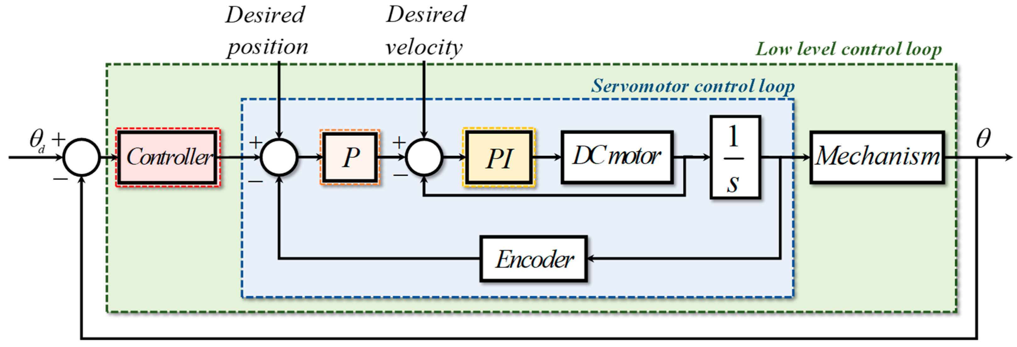
The servomotor consists of a Proportional controller for the position feedback loop, and a Proportional Integral regulator to track the desired velocities. The same model is used for both gimbal axes. Using this actuator and the low-level control loop of the gimbal system, the block diagram of the control configuration is shown in Figure 3.

3.2.1. Disturbance Suppression Compensator

An experimental approach was adopted to obtain the mathematical representations of the yaw and pitch gimbal, as well as the mutual disturbances between the two degrees of freedom [24]. The two axes of the gimbal were powered separately while identifying the system dynamics. When the yaw gimbal was powered, the mathematical model of the azimuth channel was obtained, and the disturbance on the pitch gimbal was recorded. The pitch channel mathematical representations were derived similarly. Instead of estimating the uncertainties that the system was subjected to, the novelty of this paper is the predefinition of the disturbances resulting from mutual interactions. According to this process, the transfer function of each member of the gimbal system and the corresponding mutual perturbations are described as follows:
  • G a ( s ) : The transfer function of the azimuth gimbal;
  • G e ( s ) : The transfer function of the elevation gimbal;
  • G a e ( s ) : The transfer function of the direct disturbance on the elevation gimbal;
  • G e a ( s ) : The transfer function of the direct disturbance on the azimuth gimbal.
A control configuration with two types of compensators was designed; namely, a double active control system. First, a real-time inner loop controller was designed based on the system configuration. Its objective was to cancel mutual disturbances; in other words, the predefined uncertainties. However, the control signal of this compensator can be considered a disturbance for the plant. Hence, the design of a second control system was required. The outer loop controller is a feedback controller designed based on the robust control theory for better tracking performances.
A very easy calculation defines the mathematical expression of the inner loop compensator to suppress the effect of the direct disturbance generated by one gimbal channel on the other. The disturbance compensator is denoted G ¯ i ( s ) where i = azimuth, elevation. To reject the signal of these direct disturbances from the overall output, the compensator is added to the control input.
The mathematical representation of the inner loop controller of the azimuth and elevation gimbals, respectively, are given as follows:
G ¯ a ( s ) = G e 1 ( s ) · G a e ( s ) ,
G ¯ e ( s ) = G a 1 ( s ) · G e a ( s ) .
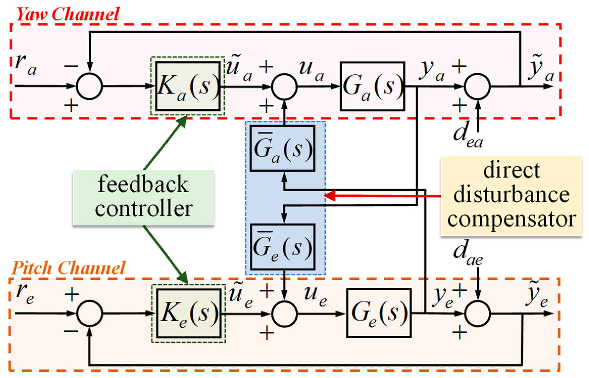
where G ¯ a ( s ) and G ¯ e ( s ) should be proper and real rational stable transfer functions. As mentioned above, the inner loop compensator was effective at suppressing the predefined mutual disturbances. However, the addition of the compensator’s signal might be a drawback, affecting the ability to achieve the desired response. This is due to the inaccurate mathematical modeling of the system (linear models), and the unpredictable uncertainties that the system is exposed to. Thus, to provide robust tracking performances, the above-presented situation has to be taken into consideration while designing the feedback controller. Hence, the gimbal system is controlled by a set of two controllers. The mutual disturbance compensators and feedback control systems suppress the parameter uncertainty and the unpredictable perturbations that may occur. The incorporation of the inner loop compensator in the control system is shown in Figure 4.
The mathematical representations of the system dynamics are
G a ( s ) = 0.2484 s 2 + 9.221 s 127.5 s 3 + 45.79 s 2 + 223.8 s + 2226 ,
G e ( s ) = 0.2118 s 2 + 3.038 s 162.4 s 3 + 16.97 s 2 + 598.5 s + 2305 .
The expressions of the mutual disturbances are given in the following equations:
G a e ( s ) = 10 4 × 0.015 s 2 + 0.8 s + 3.31 s 3 + 28 s 2 + 2957 s + 12331 ,
G e a ( s ) = 10 4 × 0.115 s 2 17.1 s 214.5 s 3 + 520.9 s 2 + 8557 s + 588.1 .
The inner loop compensators are calculated based on Equations (20) and (21), and their expressions are given as follows:
G ¯ a ( s ) = 1.15 e 05 s 5 + 0.001183 s 4 + 0.09718 s 3 + 1.339 s 2 + 8.607 s + 47.75 s 6 + 566.7 s 5 + 3.262 e 04 s 4 + 5.115 e 05 s 3 + 3.103 e 06 s 2 + 1.907 e 07 s + 1.302 e 06 ,
G ¯ e ( s ) = 1.5 e 06 s 5 5.455 e 05 s 4 0.00079 s 3 0.05004 s 2 0.3825 s 0.763 s 6 + 44.76 s 5 + 4028 s 4 + 8.086 e 04 s 3 2.045 e 06 s 2 + 1.375 e 07 s + 2.642 e 07 .

3.2.2. Feedback Controller Design

Inaccurate mathematical representations may be obtained using the experimental process to model the system dynamics. Additionally, the system may be exposed to unpredictable uncertainties. The inner loop compensator already rejects the mutual interferences, which lessens the burden on the feedback controller.
Nevertheless, some residual disturbances from the inner loop compensator, as well as unpredictable disturbances, may remain. Hence, a robust feedback control system has to be designed to enhance the tracking performance. The configuration of this control strategy is depicted in Figure 4. The feedback controllers K a ( s ) and K e ( s ) are, respectively, the azimuth and elevation gimbal controllers, designed based on the H framework.
a. H Control Problem
The objective of the H control theory is to handle two major robustness issues. The first is to find a stabilizing controller, such that the norm of the Linear Fractional Transformation (LFT) is minimized, for the minimization of the maximum error energy [27]. The second objective is to preserve the stability of the closed loop under unpredictable uncertainties with a bounded H norm. The standard H problem is stated as
T z w i < γ ( > 0 ) ,   where   i = yaw , pitch .
Several convenient algorithms were studied and developed to solve the preceding problem, for instance by solving the two Riccati equations in Doyle et al.’s work [28]. However, in this study, instead of the classic representation of the H controller, a mixed sensitivity H control configuration was considered.
b.Mixed Sensitivity Problem
Let G ( s ) denote the plant transfer matrix, and let K ( s ) denote the controller transfer matrix. The sensitivity function denoted as S ( s ) and the complementary sensitivity function denoted as T ( s ) are given by
S ( s ) = ( I + G K ) 1 ( s ) ,
T ( s ) = I S ( s ) = G K ( I + G K ) 1 ( s ) .
The minimization of the sensitivity function is possible at lower frequencies. On the other hand, the complementary sensitivity function is minimized at high frequencies, which handles the unstructured uncertainties and noises. The mixed sensitivity problem considered in this study is an S / T configuration, in which the controller K ( s ) is obtained to minimize the cost of the closed loop, Equation (28), and satisfy the nominal performance and robust stability [29]. The new H mixed sensitivity problem is denoted as
T z w i = W S i ( I + G i K i ) 1 W T i G i K i ( I + G i K i ) 1   where   i = azimuth ,   elevation .
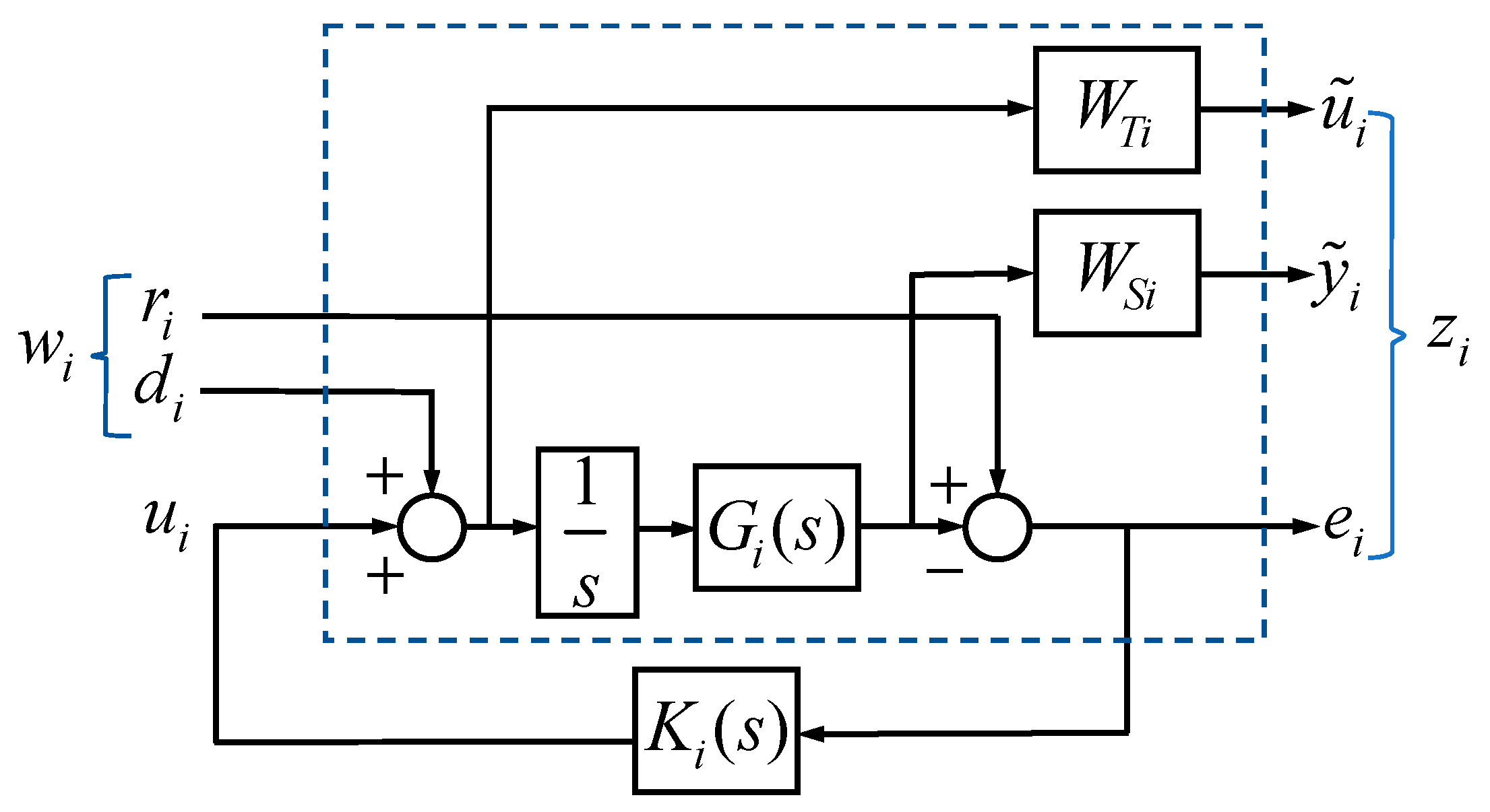
In Equation (31), W S i and W T i are the frequency-dependent weighting functions that depend on the characteristics of the disturbances. With W T i scaling the direct disturbances and W S i prioritizing the direct compensator, the feedback controller is obtained.
However, the response of the system to a step signal shows the instability of the internal model of the system, because the H control framework does not have any means to constrain the resulting controller to have one or more poles in the origin of the s-plane, [30,31]. Therefore, to overcome this problem, an integral action is introduced to the preceding mixed sensitivity H controller.
Two basic methods serve to introduce this integral action:
  • Introducing poles at the origin in the weighting filters related to the system error; an integrator is expected to appear in the controller to account for the error requirement.
  • Adding integrators in series with the plant; the H controller is calculated for the augmented plant.
The second alternative mentioned above has the drawback of producing a controller of a higher order than should be necessary. The first alternative, however, presents some numerical difficulties, since the pole at the origin is not observable nor controllable from the viewpoint of the closed-loop signals. This precludes the application of conventional H control design techniques. To solve this issue, we can replace the exact integrator by an approximation, as shown by the following:
1 s + ε   with ε   is   chosen   to   be   very   small ( ε = 0.0001 ) .
The corresponding H controller with the integral action in the forward path is illustrated in Figure 5. After several iterations, the resulting controller is of high order; therefore, Hankel singular values-based balanced reduction are used [29].
The computed H -based controller of the azimuth K a ( s ) and the elevation, K e ( s ) gimbals are as follows:
K a ( s ) = N a ( s ) D a ( s ) ,
N a ( s ) = s 9 + 1046 s 8 + 7.902 e 04 s 7 + 2.251 e 06 s 6 + 3.626 e 07 s 5 + 3.492 e 08 s 4 + 2.671 e 09 s 3 + 1.104 e 10 s 2 + 4.057 e 10 s + 2.747 e 09
D a ( s ) = s 9 + 1046 s 8 + 7.905 e 04 s 7 + 2.253 e 06 s 6 + 3.633 e 07 s 5 + 3.501 e 08 s 4 + 2.679 e 09 s 3 + 1.108 e 10 s 2 + 4.069 e 10 s + 2.755 e 09
K e ( s ) = N e ( s ) D e ( s ) ,
N e ( s ) = s 8 + 56.72 s 7 + 5094 s 6 + 1.528 e 05 s 5 + 5.15 e 06 s 4 + 8.097 e 07 s 3 + 1.274 e 09 s 2 + 7.521 e 09 s + 1.368 e 10
D e ( s ) = s 8 + 56.91 s 7 + 5105 s 6 + 1.537 e 05 s 5 + 5.177 e 06 s 4 + 8.19 e 07 s 3 + 1.287 e 09 s 2 + 7.732 e 09 s + 1.435 e 10
The weighting functions were chosen based on the system characteristics and the mutual disturbances that the system is subjected to, and they are proper and analytic in the right half of the s-plane. These weighting functions were chosen as
W T a ( s ) = 50 s 6 + 5 e 05 s 5 + 1.65 e 06 s 4 + 2.57 e 07 s 3 + 1.557 e 08 s 2 + 9.05 e 08 s + 6.17 e 07 s 6 + 1000 s 5 + 3.3 e 04 s 4 + 5.14 e 05 s 3 + 3.114 e 06 s 2 + 1.81 e 07 s + 1.234 e 06 ,
W S a ( s ) = 0.5 s 3 + 260.5 s 2 + 4278 s + 289.8 s 3 + 520.9 s 2 + 8557 s + 588.1 ,
W T e ( s ) = 50 s 6 + 2238 s 5 + 2.014 e 05 s 4 + 4.04 e 06 s 3 + 1.023 e 08 s 2 + 6.877 e 08 s + 1.321 e 09 s 6 + 44.76 s 5 + 4028 s 4 + 8.08 e 04 s 3 + 2.045 e 06 s 2 + 1.375 e 07 s + 2.642 e 07 ,
W S e ( s ) = 0.5 s 3 + 14 s 2 + 1479 s + 6166 s 3 + 28 s 2 + 2957 s + 12331 .
where W S a and W T a are properties of the azimuth (yaw) channel, along with W S e and W T e representing the elevation (pitch) channel.

3.3. The Proposed Control Algorithm Implementation

The calculation and implementation of the proposed controller can be summarized in the following steps:
  • The dynamics of the two-axis gimbal are identified experimentally. The channels of the gimbal system are powered on separate occasions, and when the yaw gimbal is active its transfer function is obtained. The effect of the yaw channel on the non-powered pitch channel is recorded. Then, the mathematical representation is calculated using the System Identification toolbox of MATLAB software, and vice versa for the pitch channel.
  • The inner loop controllers of the azimuth and elevation gimbals are calculated using Equations (20) and (21).
  • The mixed sensitivity configuration of the H control framework requires the definition of weighting functions. The mutual disturbances are chosen as the weighting function W S since they interfere with the overall output.
  • On the other hand, even though the inner loop controller helps suppress the mutual disturbances, it is considered as a disturbance to the control input. Therefore, the weighting function W T is simply chosen as the inner loop compensator, with minor modification during the calculation of the H controller.
  • The computation of the H -based controller is done using the MATLAB software; the function ‘hinfsyn’ is used.
  • The order reduction algorithm is not necessary after determining the feedback controller. The balanced truncation reduces the order of high-order representation (Hankel singular values).
The first five steps are necessary steps to design this controller, but the last step is optional. An order reduction might be necessary if the high-order controllers may cause lagging in real applications due to the long time needed for computations in real time.

4. Experiment and Results: Control of the High-Precision Gimbal System

4.1. Mutual Disturbances Effect

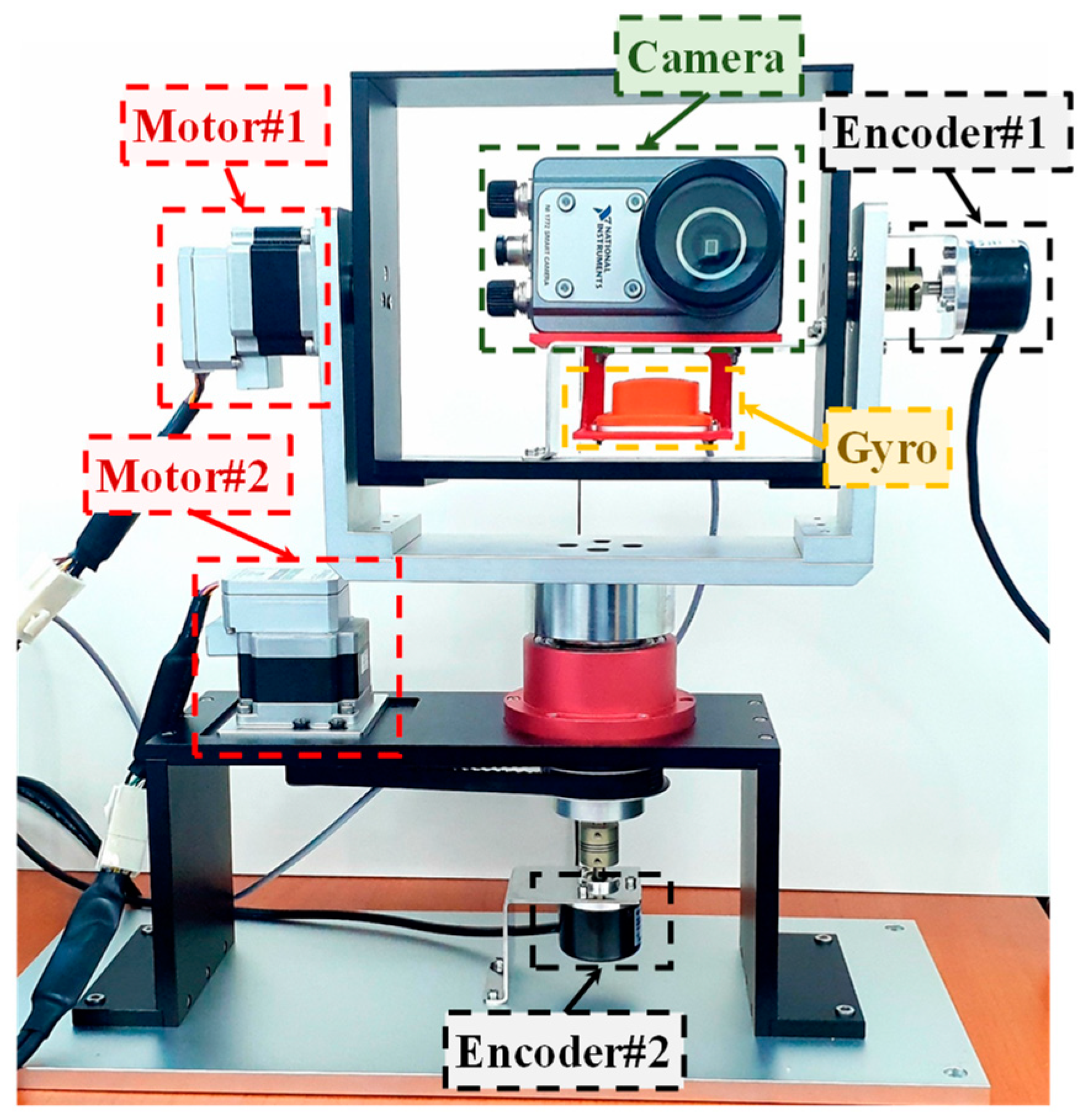
The experimental apparatus used for this study is illustrated in Figure 6. It consists of two DC servomotors CM1-23C30S, a gyro sensor XSENS MTi-28A53G35, and a National Instruments smart camera model NI 1772. The camera is used only as a payload in this study. The mounted encoders were used to identify the system dynamics.
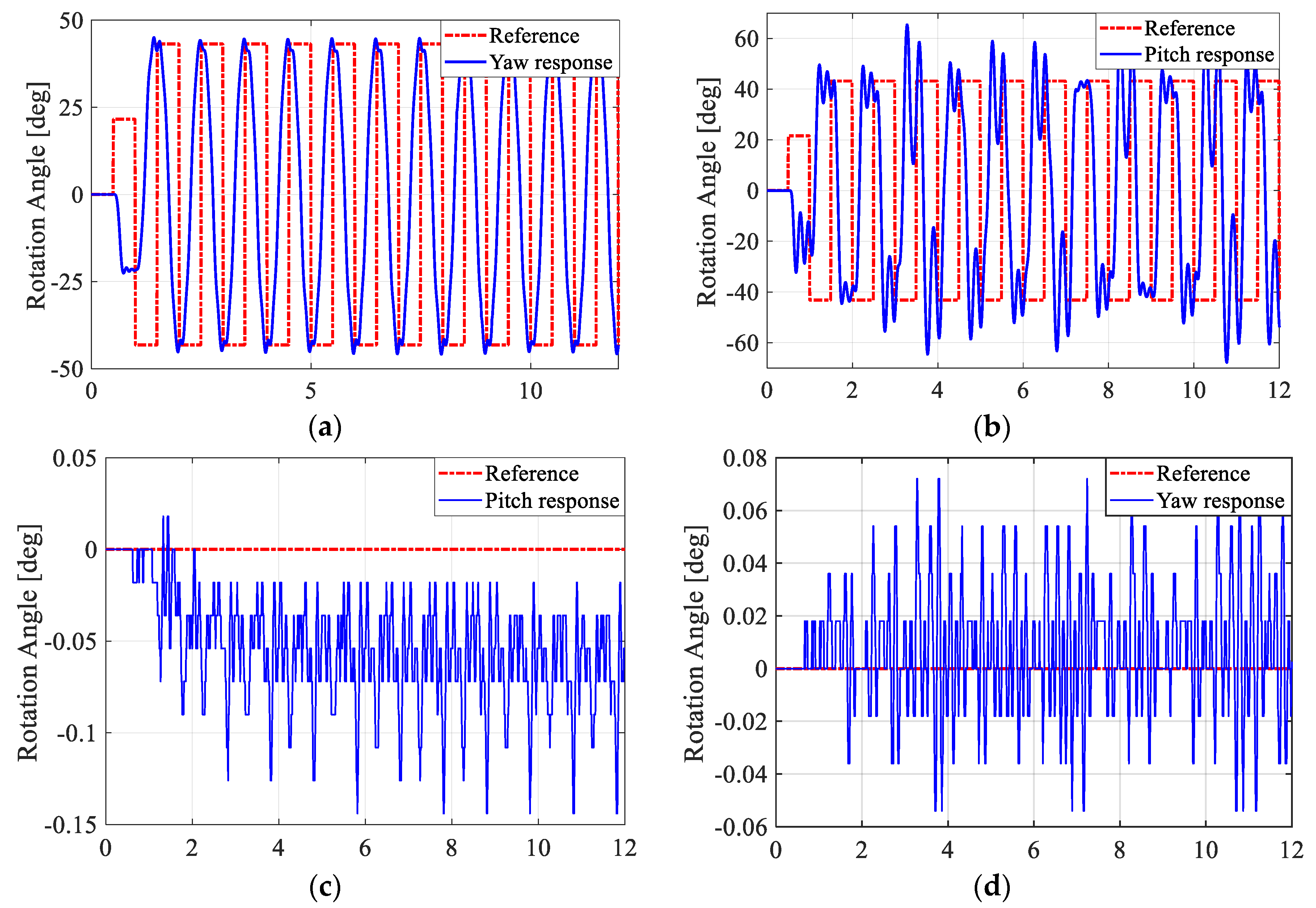
The first set of experimental results, depicted in Figure 7, show the uncontrolled responses of the yaw and pitch channels powered one at a time. Figure 7a represents the response of the powered yaw channel, and Figure 7c—the effect of this motion on the pitch channel. Figure 7b shows the uncontrolled response of the now active pitch channel, and Figure 7d—the effect of this action on the pitch channel.
Certainly, the effect of each channel is not considered an issue in a small field of view. However, when installed on naval systems or aerial vehicles, ISP systems are required to monitor a wide area. In this case, the slightest vibration of the gimbal camera system will lead the LOS to deviate from the target.
If the distance between the target and the ISP is known, and with data shown in Figure 7c,d, we can confirm the effect of the mutual disturbances on the precision of these systems. For instance, if a target is situated 500 m away from the ISP, the effect on the pitch channel is −0.14°, and the disturbance on the yaw channel is 0.07°. Then, the pitch channel deviates from the target by −1.22 m and the yaw channel by a distance of 0.66 m. Thus, the precision of the gimbal camera system is lost. Since gimbaled camera systems demand high-precision performance, the slightest deviation of the camera focus in real field applications is considered very detrimental and undesirable. Moreover, reducing the controller workload results in economizing the energy necessary to reach the objective of the control system. Therefore, it is beneficial for the overall performance of the system if these mutual interferences are canceled.

4.2. Experiment Methodology

In this section, the designed double active control system and the ISMC regulator are investigated. The experiments were conducted on a two-axis gimbal system intended for marine surveillance purposes. Two main tasks required of the ISPs, motion tracking and target tracking, are addressed, and are the objective of this experimental study. The LOS stabilization was direct in this case, since the rate sensor was mounted in line with the LOS axis.
The first trial scenario was to command the actuators of both axes of the gimbal to rotate by a predefined angle (data acquired from a radar.) The second set of trials was for the motion tracking problem. The desired trajectory of the motion tracking task is a circular path, and needless to say, the center of the LOS coincides with the center of the circular path at the beginning of the experiment. The trajectory generation process is described in Figure 8.
The radius of the circular track is denoted r , and the distance between the gimbal system and the target is l . θ is the rotation of the pitch gimbal, ψ is the yaw gimbal angle of rotation, and α represents the rotation angle of the LOS on the actual trajectory.
Through a simple mathematical calculation, the angle of rotation communicated to the pitch and the yaw actuators, respectively, was as follows:
θ = arctan ( y l ) = arctan ( r sin α l ) ,
ψ = arctan ( x l ) = arctan ( r cos α l ) .

4.3. Results

Feedback control was achieved by implementing the designed controllers described in Equations (33) and (34), as well as the inner loop compensators presented in Equations (26) and (27). The experiments were conducted using the ISMC controller whose parameters were defined in Table 1.
For the first test scenario, the pitch and yaw gimbals were powered and rotation commands were given simultaneously to test the robustness of the control systems. The actual rotation angle measurements of these tests are portrayed in Figure 9.
From the figures above, the designed controller smoothly and rapidly tracked the target angle with minimum steady-state error compared to the ISMC, which had a slow response, as seen in Figure 9a,b. The yaw channel, especially for the ISMC, struggled to reach the desired angle. In Figure 9c,d, the designed controller attenuated the control input without difficulty and rapidly compared to the ISMC. The effect of the mutual disturbances was less apparent thanks to the inner loop compensator used for both of the control strategies proposed. From the figures above, the designed controller easily tracked the target angle with minimum steady-state error compared to the ISMC.
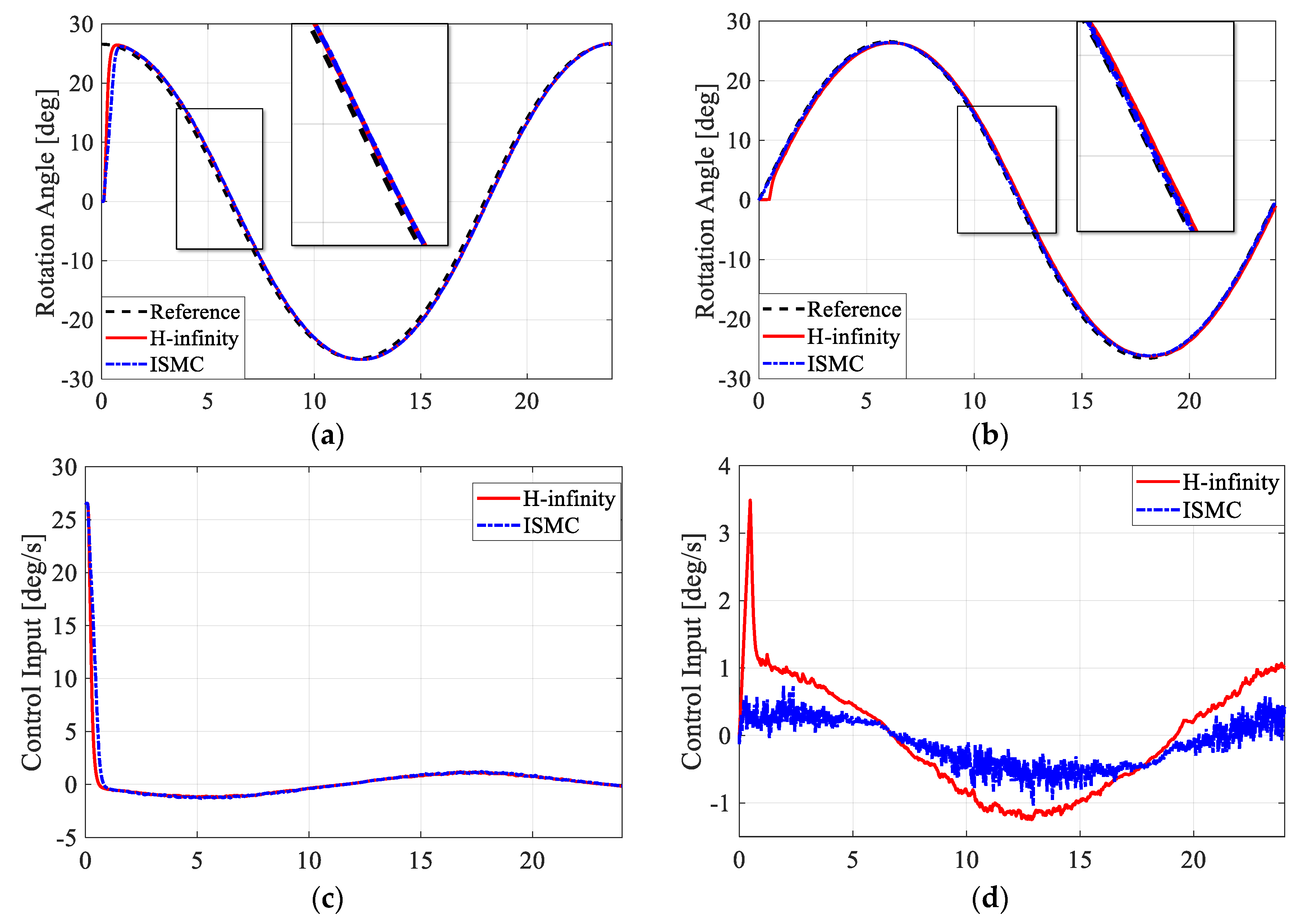
For the second scenario, Figure 10 and Figure 11 represent the results of the motion tracking quest. Figure 9 depicts the resulting circular trajectory of the LOS using the two control strategies. Figure 11a,b portray the resulting motion of the two gimbal channels, and Figure 11c,d illustrate the control input applied to the plant. The speed of the motion to track was set to 15 deg/s. The radius of the track was r = 50 m, and the distance between the gimbal and the target was l = 100 m.
One can conclude from the previous figures that the LOS follows the predefined circular trajectory well when using the two control techniques (Figure 10). However, the control inputs vary significantly from the yaw to the pitch gimbals (Figure 11). One thing worth mentioning is that the mechanical structure of the pitch channel is not desirable for inertial systems. The motor is directly coupled with the mechanism, which creates more uncertainties for the system to cope with. A quick look at Figure 11c,d shows the importance of coupling technologies between actuators and mechanical structures, especially in inertial systems.
Both control systems provide a good tracking performance. However, the performance varies according to the type of reference signal. Due to the mechanical structure of the pitch gimbal, the control input using the ISMC is unstable, and does not cope with the added constraint as smoothly as the designed controller (Figure 11d). Despite the unstable control input, the ISMC performs well in the motion tracking tests where the reference signal is continuous. However, when the reference signal is a pulse-type signal, the ISMC performs poorly in the target tracking experiments compared to the proposed control strategy. The ISMC rise time of the yaw channel, especially, is slower, which is not desirable. Briefly, the proposed control strategy performs somewhat better than the ISMC, which makes a difference in high-precision systems.

5. Conclusions

In this paper, the authors suggested a new control scheme based on the system dynamics to ensure better stabilization and enhance the tracking performances of a two-axis gimbal system. The novelty of this approach is in the exact modeling of the mutual disturbances, and the active compensation for their impact on the system performances.
The system dynamics were developed using the Newton–Euler law, where the eminent influence of the mutual disturbances is highlighted, especially if the system is of unbalanced mass distribution (as in the current case). On a second note, two robust control systems were designed. The proposed control scheme consists of two compensators, including an inner loop compensator that deals with the mutual disturbances that were experimentally determined. The second compensator is a robust feedback controller that assures better disturbance rejection and enhances control performance. Two control strategies were considered in this study: an Integral Sliding-Mode Controller (ISMC) and a robust controller designed based on the H framework.
To test the efficiency of the ISMC and the designed controller, two different experimental scenarios were presented. These included target tracking, which requires the gimbal channels to rotate by a certain angle, and motion tracking, which demands collaborated movement of the gimbal system’s two-axes. The experiment achieved promising results for the designed controller in maintaining the stability of the system, as well as enhancing the tracking performance. Without a doubt, ISMC is a very reliable control scheme for systems with nonlinear properties; however, based on the experiments conducted here, the proposed controller is more stable.
In short, the uncertainties surrounding the gimbal system can degrade the desired tracking performance. More specifically, in this paper, the mutual disturbances between the gimbal system’s degrees of freedom were discussed, defined, and rejected. The suppression of these disturbances reduces the workload of the feedback controller, which reduces energy consumption. This is a desirable feature for systems in high-uncertainty work environments.

Author Contributions

Conceptualization, Y.-B.K. and S.C.; methodology, S.C. and Y.-B.K.; software, S.C. and D.-Q.T.; validation, S.C., D.-H.L. and Y.-B.K.; writing—original draft preparation, S.C.; writing—review and editing, Y.-B.K. and S.C.; supervision, Y.-B.K. All authors have read and agreed to the published version of the manuscript.

Funding

This research received no external funding.

Conflicts of Interest

The authors declare no conflict of interest.

References

  1. Masten, M.K. Inertially Stabilized Platforms for Optical Imaging Systems. IEEE Control Syst. 2008, 28, 47–64. [Google Scholar] [CrossRef]
  2. Kennedy, P.J.; Kennedy, R.L. Direct versus indirect line of sight (LOS) stabilization. IEEE Trans. on Control Syst. Technol. 2003, 11, 3–15. [Google Scholar] [CrossRef]
  3. Smith, B.J.; Schrenk, W.J.; Gass, W.B.; Shtessel, Y.B. Sliding mode control in a two-axis gimbal system. IEEE Aerosp. App. Conf. Proc. 1999, 5, 457–470. [Google Scholar] [CrossRef] [Green Version]
  4. Seong, K.J.; Kang, H.G.; Yeou, B.Y.; Lee, H.P. The Stabilization Loop Design for a Two-Axis Gimbal System Using LQG/LTR Controller. In Proceedings of the 2006 SICE-ICASE International Joint Conference, Busan, Korea, 18–21 October 2006; pp. 755–759. [Google Scholar] [CrossRef]
  5. Seong, K.J.; Kang, H.G.; Yeou, B.Y.; Lee, H.P. The digital anti-windup LQG/LTR controller design for a two-axis gimbal system. In Proceedings of the 2007 International Conference on Control, Automation and Systems, Seoul, Korea, 17–20 October 2007; pp. 1717–1720. [Google Scholar] [CrossRef]
  6. Hastürk, Ö.; Erkmen, A.M.; Erkmen, İ. Proxy-Based Sliding Mode Stabilization of a Two-Axis Gimbaled Platform. In Proceedings of the World Congress on Engineering and Computer Science, San Francisco, CA, USA, 19–21 October 2011. [Google Scholar]
  7. Naderolasli, A.; Tabatabaei, M. Stabilization of the Two-Axis Gimbal System Based on an Adaptive Fractional-Order Sliding-Mode Controller. IETE J. Res. 2017, 63, 124–133. [Google Scholar] [CrossRef]
  8. Mao, J.; Yang, J.; Li, S.; Li, Q. Output Feedback Stabilization of Inertial Stabilized Platform with Unmatched Disturbances Using Sliding Mode Approach. IFAC-PapersOnLine 2017, 50, 5149–5154. [Google Scholar] [CrossRef]
  9. Kürkçü, B.; Kasnakoǧlu, C.; Efe, M.Ö. Disturbance/Uncertainty Estimator Based Integral Sliding-Mode Control. IEEE Trans. Automat. Contr. 2018, 63, 3940–3947. [Google Scholar] [CrossRef]
  10. Kürkçü, B.; Kasnakoǧlu, C.; Efe, M.Ö. Disturbance/Uncertainty Estimator Based Robust Control of Nonminimum Phase Systems. IEEE/ASME Trans. Mechatronics 2018, 23, 1941–1951. [Google Scholar] [CrossRef]
  11. Sangveraphunsiri, V.; Malithong, K. Control of Inertial Stabilization Systems Using Robust Inverse Dynamics Control and Sliding Mode Control. In Proceedings of the 6th International Conference on Automotive Engineering (ICAE-6) BITEC, Bangkok, Thailand, 29 March–2 April 2010; Volume 1, pp. 1–10. [Google Scholar]
  12. Wongkamchang, P.; Sangveraphunsiri, V. Control of Inertial Stabilization Systems Using Robust Inverse Dynamics Control and Adaptive Control. Thammasat Int. J. Sc. Tech. 2008, 13, 20–32. [Google Scholar]
  13. Mao, J.; Li, S.; Li, Q.; Yang, J. Design and implementation of continuous finite-time sliding mode control for 2-DOF inertially stabilized platform subject to multiple disturbances. ISA Trans. 2019, 84, 214–224. [Google Scholar] [CrossRef]
  14. Abdo, M.; Vali, A.R.; Toloei, A.R.; Arvan, M.R. Modeling control and simulation of two axes gimbal seeker using fuzzy PID controller. In Proceedings of the 2014 22nd Iranian Conference on Electrical Engineering (ICEE), Tehran, Iran, 20–22 May 2014; pp. 1342–1347. [Google Scholar] [CrossRef]
  15. Königseder, F.; Kemmetmüller, W.; Kugi, A. Attitude control strategy for a camera stabilization platform. Mechatronics 2017, 46, 60–69. [Google Scholar] [CrossRef]
  16. Li, H.; Ning, X.; Han, B. Composite decoupling control of Gimbal Servo System in double-gimbaled variable speed CMG Via disturbance observer. IEEE/ASME Trans. Mechatronics 2017, 22, 312–320. [Google Scholar] [CrossRef]
  17. Khodadadi, H.; Motlagh, M.R.J.; Gorji, M. Robust control and modeling a 2-DOF inertial stabilized platform. In Proceedings of the International Conference on Electrical, Control and Computer Engineering 2011 (InECCE), Pahang, Malaysia, 21–22 June 2011; pp. 223–228. [Google Scholar] [CrossRef]
  18. Khayatian, M.; Aghaee, P.K. Adaptive control of a two-axis gimbal system using modified error. In Proceedings of the 3rd International Conference on Control, Instrumentation, and Automation, Tehran, Iran, 28–30 December 2013; pp. 1–5. [Google Scholar] [CrossRef]
  19. Zhou, X.; Zhang, H.; Yu, R. Decoupling control for two-axis inertially stabilized platform based on an inverse system and internal model control. Mechatronics 2014, 24, 1203–1213. [Google Scholar] [CrossRef]
  20. Krishnamoorthy, J.A.R.; Marathe, R.; Sule, V.R. H control law for line-of-sight stabilization for mobile land vehicles. Opt. Eng. 2002, 41. [Google Scholar] [CrossRef]
  21. Kodhanda, A.; Kolhe, J.P.; Kuber, M.M.; Parlikar, V.V. Uncertainty and Disturbance Estimation based Control of Three-axis Stabilized Platform. Int. J. Latest Trends Eng. Technol. (IJLTET) 2014, 3, 289–297. [Google Scholar]
  22. Li, H.; Zheng, S.; Ning, X. Precise Control for Gimbal System of Double Gimbal Control Moment Gyro Based on Cascade Extended State Observer. IEEE Trans. Ind. Electron. 2017, 64, 4653–4661. [Google Scholar] [CrossRef]
  23. Kürkçü, B.; Kasnakoğlu, C. Estimation of Unknown Disturbances in Gimbal Systems. Appl. Mech. Mater. 2015, 789–790, 951–956. [Google Scholar] [CrossRef]
  24. Chakir, S.; Suh, J.H.; Ji, S.W.; Kim, Y.B. A composite control design for suppressing mutual interference of interconnected systems. J. Mech. Sc. Technol. 2020, 34, 867–875. [Google Scholar] [CrossRef]
  25. Ekstrand, B. Equations of motion for a two-axis gimbal system. IEEE Trans. Aerosp. Electron. Syst. 2001, 37, 1083–1091. [Google Scholar] [CrossRef]
  26. Abdo, M.; Vali, A.R.; Toloei, A.; Arvan, M.R. Research on the cross-coupling of a two axes gimbal system with dynamic unbalance. Int. J. Adv. Robot. Syst. 2013, 10. [Google Scholar] [CrossRef] [Green Version]
  27. Gu, D.W.; Petkov, P.H.; Konstantinov, M.M. H Design. In Advanced Textbooks in Control and Signal Processing: Robust Control Design with MATLAB, 2nd ed.; Springer: London, UK, 2013; pp. 31–48. [Google Scholar]
  28. Doyle, J.C.; Glover, K.; Khargonekar, P.P.; FRANCIS, B.A. State-Space Solutions to Standard H2 and H Control Problems. IEEE Trans. Automat. Contr. 1989, 34, 831–847. [Google Scholar] [CrossRef]
  29. Zhou, K.; Doyle, J.C. Essentials of Robust Control, 1st ed.; Prentice Hall: Upper Saddle River, NJ, USA, 1998; pp. 81–128. [Google Scholar]
  30. Miranda, M.F.; Takahashi, R.H.C.; Jota, F.G. H controllers with integral action: An experimental evaluation. Proc. Inst. Mech. Eng. Part I J. Syst. Control Eng. 2010, 224, 21–29. [Google Scholar] [CrossRef]
  31. Miranda, M.F.; Jota, F.G.; Takahashi, R.H.C. On H controllers with integral action: An experimental evaluation. IFAC Proc. Vol. 2002, 15, 419–424. [Google Scholar] [CrossRef]
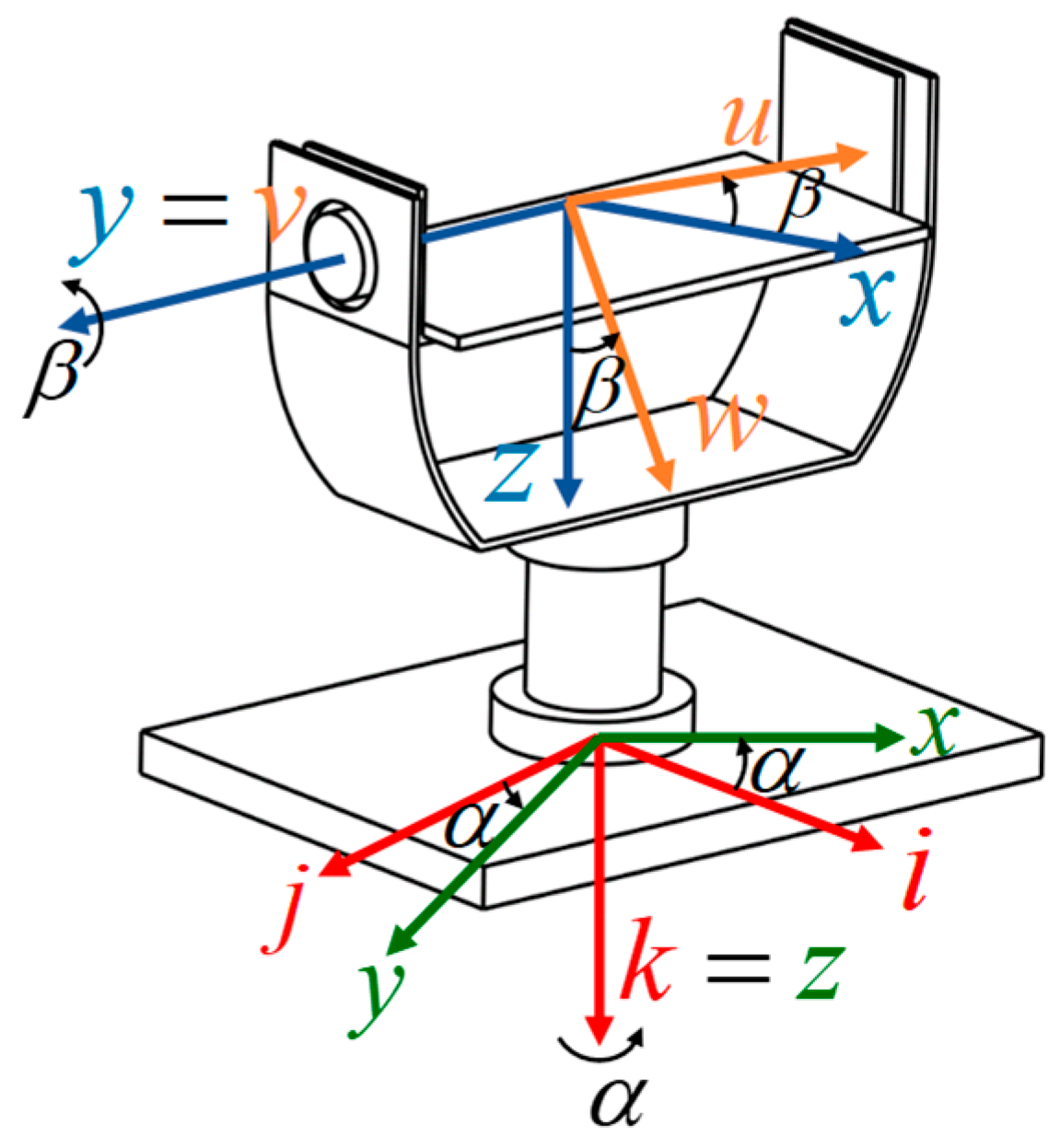
Figure 1. The two-axis gimbal system.
Electronics 09 01638 g001
Figure 2. Integral sliding-mode controller (ISMC) block diagram.
Electronics 09 01638 g002
Figure 3. Integrated servomotor configuration and ISP mechanism.
Electronics 09 01638 g003
Figure 4. Block diagram of the proposed controller.
Electronics 09 01638 g004
Figure 5. Schematic of the S / T mixed sensitivity design with an integrator inserted in the control input path.
Electronics 09 01638 g005
Figure 6. Experiment apparatus of the 2-DOF gimbal system.
Electronics 09 01638 g006
Figure 7. The uncontrolled response of the gimbal system. The rotation angle of the yaw gimbal (a), and its effect on the pitch gimbal (c). The rotation angle of the pitch gimbal (b), and (d) is the resulting motion of the yaw gimbal.
Electronics 09 01638 g007
Figure 8. Circular trajectory generation for motion tracking.
Electronics 09 01638 g008
Figure 9. Target tracking performance of the two-axis gimbal system. Rotation angle tracking of the yaw gimbal (a), and the pitch gimbal (b). The control input to the yaw gimbal (c), and (d) is the control input to the pitch gimbal.
Electronics 09 01638 g009
Figure 10. The circular trajectory of the line of sight (LOS) using the two control techniques.
Electronics 09 01638 g010
Figure 11. Motion tracking performance of the two-axis gimbal system. Rotation angle tracking of the yaw gimbal (a) and the pitch gimbal (b). The control input to the yaw gimbal (c), and (d) is the control input to the pitch gimbal.
Electronics 09 01638 g011
Table 1. ISMC parameters.
ParametersPitch ChannelYaw Channel
λ 100200
k 0 15.525.5
α 0 2.62.6