Article

A Novel Non-Isolated Three-Port Bidirectional DC/DC Converter for Photovoltaic Electric Scooter Charging Stations

Department of Electronic Engineering, National Kaohsiung University of Science and Technology, Kaohsiung 824, Taiwan
*
Author to whom correspondence should be addressed.
Electronics 2020, 9(10), 1741; https://doi.org/10.3390/electronics9101741
Submission received: 3 September 2020 / Revised: 24 September 2020 / Accepted: 19 October 2020 / Published: 21 October 2020
(This article belongs to the Section Power Electronics)

Abstract

:
This paper proposes a novel non-isolated three-port bidirectional dc/dc converter for photovoltaic (PV) electric scooter (ES) charging stations. The proposed converter combines an improved boost converter and a bidirectional buck-boost converter. When the PV energy is sufficient, the PV module is stepped up to provide dc load energy to the ES through the improved boost converter in order to charge the ES battery. When the PV energy is insufficient, the storage battery is stepped up to provide energy to the ES load dc bus, and the ES load dc bus charges the battery if the battery energy is low. The proposed converter reduces the number of components and circuit cost by using a switch internal diode. Finally, a 400-W modified boost converter and a 120-W/60-W bidirectional boost-buck converter were implemented to verify the three operating modes of the proposed non-isolated dc/dc converter. The results revealed that the highest efficiency levels achieved under PV module step-up, storage battery step-up, and storage battery step-down operation were 97.5%, 96.6%, and 92%, respectively.

1. Introduction

With the increasing awareness of environmental protection, solar power has come to be regarded as an attractive energy source. Solar panels have become optimal representatives of green energy under strong sunlight conditions. In addition, pollutants such as carbon dioxide, sulfur dioxide, nitrogen oxides, PM2.5, and volatile organic compounds are becoming considerably critical. People are paying attention to carbon dioxide and waste generated from gasoline and diesel vehicles. People are gradually accepting electric vehicles (EVs) because of their cleanness; moreover, EVs have become mainstream in several countries worldwide [1]. In Taiwan, because of the narrow roads and dense population, motorcycles constitute the primary transportation vehicles. Asia has the highest density of motorcycles in the world. In recent years, the popularity of electric scooters (ESs) has increased gradually. Although ES use can reduce fuel emissions, it is still marred by several limitations. For example, the power supply of ESs is a major problem for ES riders. Additional drawbacks include the limited availability of charging stations, large battery storage space, long charging time, and battery life.
Despite the aforementioned limitations, ESs have become a major factor in the future development of transportation systems in Taiwan; hence, improving ES charging systems is becoming increasingly crucial. Accordingly, photovoltaic (PV) power generation and ES charging have been combined to construct a highly convenient and environmentally friendly system. The market share of ESs is expected to grow substantially [2].
In general, a large gap exists between the output voltage of green energy systems and the voltage demand of an ES bus (load bus). Therefore, a set of boost converters is required. Only traditional boost, single-ended step-up, converters are used for ESs. Converters cannot be combined with energy storage systems to develop a converter system [3]. To effectively charge and discharge energy storage systems, a bidirectional buck-boost circuit is required [4]. In addition, a bidirectional buck-boost circuit should be used to step-up green energy to the ES bus. These requirements cannot be realized using traditional converters [5,6,7,8,9,10,11,12,13,14]. Accordingly, this study developed a novel nonisolated three-port bidirectional dc/dc converter for PV ES charging stations.
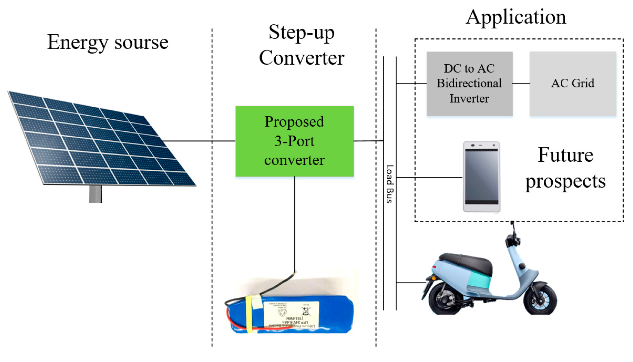
Figure 1 illustrates a block diagram of a green energy application. Green energy such as PV or wind energy constitutes the energy source of the dc/dc converter, and the design objective of this converter is to achieve high efficiency, small size, and low cost. Energy storage systems for PV system applications currently constitute a major research direction for scholars. In a system with battery energy storage, the storage battery voltage may differ considerably from the load bus terminal voltage; hence, a dc/dc converter with a step-up function is also required. Moreover, a step-down converter is required to charge the storage battery. Therefore, bidirectional converters that can achieve step-up and step-down functions in the same topology should be designed. Accordingly, reducing the size, cost, and component count of converters is a critical problem. Recently, several non-isolated [15,16,17] and isolated [18,19,20,21,22,23,24] bidirectional converters have been proposed for conversion of different voltages.
A previous study proposed an improved boost/buck bidirectional converter with step-up/step-down functions and a substantial cost; however, its boost and buck efficiencies are poor [25]. Furthermore, [26] is presented an improved boost/buck converter with a coupling inductor. The topology for this converter comprises two switches and a coupling inductor; its output power is only 100 W and efficiency is low. Another study developed a bidirectional converter between a battery terminal and dc bus terminal with a transformer [27]; the topology for this converter comprises four switches used to implement a 200-W output power. The staggered control method reduces the input ripple current but increases the complexity of its control and circuit.
Recently, several scholars have proposed three-terminal converter topologies [28,29,30,31]. Specifically, [28] proposed a non-isolated three-port converter with an energy storage system and PV. In this topology, a relatively high number of operating modes, switches, and diode components are used, resulting in poor efficiency. The converter proposed in [29] is based on an isolated topology with a transformer as well as three switches and four Schottky diodes; an LCL resonant circuit is also added to the primary side. However, the disadvantages of this topology are its complex structure, high cost, and poor efficiency. In [30], a unidirectional converter and bidirectional converter were combined with an energy storage system; this converter is based on a highly complicated and isolated topology comprising two switches and four Schottky diodes. However, the output power of the converter is only 150 W, and it cannot efficiently execute charge/discharge and power supply to the load bus simultaneously.
Figure 2 illustrates the proposed three-port bidirectional converter. When the PV energy is sufficient, the battery is charged and energy is supplied to the dc bus. When the PV energy is insufficient, the battery can supply energy to the dc bus. This topology contains different operating modes; thus, it can considerably reduce the circuit cost and size.

2. Proposed Converter and Operating Principles

Figure 3 illustrates the proposed three-port non-isolated step-up/step-down bidirectional dc/dc converter for PV ES charging stations. The converter topology comprises a unidirectional boost converter combined with an improved bidirectional buck/boost converter. The unidirectional boost converter is used to step up the PV module output to the ES load bus. The bidirectional buck/boost converter serves as the interface between the storage battery and ES load bus. If the energy of the ES load bus is sufficient, it is stepped down to charge the storage battery. However, if the energy of the ES load bus is insufficient, the storage battery output is stepped up to charge the ES load battery. The auxiliary inductance LBat at the port of the storage battery can change the output voltage of the ES load bus and provide a continuous current to charge the storage battery. The proposed topology focuses on combining PV energy, ES load battery, and storage battery energy; it comprises three switches (S1S3), a Schottky diode (D1), two inductors (LIn and LBat), and three capacitors (CIn, CLoad, and CBat).
The proposed three-port bidirectional dc/dc converter involves three operating modes. In the first mode, when the PV energy is sufficient, the PV module output is stepped up to the ES bus to charge the ES battery. In the second mode, when the ES bus has sufficient energy, the output is stepped down to charge the storage battery. In the third mode, when the storage battery has sufficient energy and no PV output, the storage battery provides energy to the ES bus and charges the ES battery.
To simplify the circuit analysis, the following assumptions can be made:
(1)
The capacitance levels of Cin, CLoad, and CBat are sufficiently high, and the output voltage can be maintained as a constant voltage source.
(2)
All switches S1, S2, and S3 and diode D1 are ideal components.
(3)
The inductor current is in continuous mode (maintains a positive value).
(4)
The switching period is T, the turned-on time of the switches is DT, and the turned-off time of the switches is 1 − DT.
A.
Stage 1: The PV output voltage is stepped up to the ES bus to charge the ES battery
When the energy supplied from the PV modules is sufficient, the PV module voltage is stepped up to the ES bus to charge the ES battery. Figure 4 illustrates the waveform of the operation of the main components in Stage 1.
a.
Mode 1 [t0t < t1]
When t = t0, S1 is turned on; S2, S3, and S4 are turned off; and D1 is turned off. Figure 5a presents the current flow direction. In this mode, the PV voltage provides energy for storage in the inductor LIn. At this time, the ES load is provided by CLoad.
b.
Mode 2 [t1t < t2]
When t = t1, S1 is turned off and S2 and S4 are continuously turned off. At this time, D1 is turned on. Figure 5b presents the current flow direction. In this mode, the energy of the inductor LIn is supplied to the ES bus, and the ES battery is charged by D1.
B.
Stage 2: ES bus is stepped down to charge storage battery
When the energy supplied by the PV modules is insufficient and the storage battery requires charging, the output voltage of the ES bus is stepped down to charge the storage battery. Figure 6 presents the waveforms of the operation of the main components in Stage 2.
a.
Mode 1 [t0t < t1]
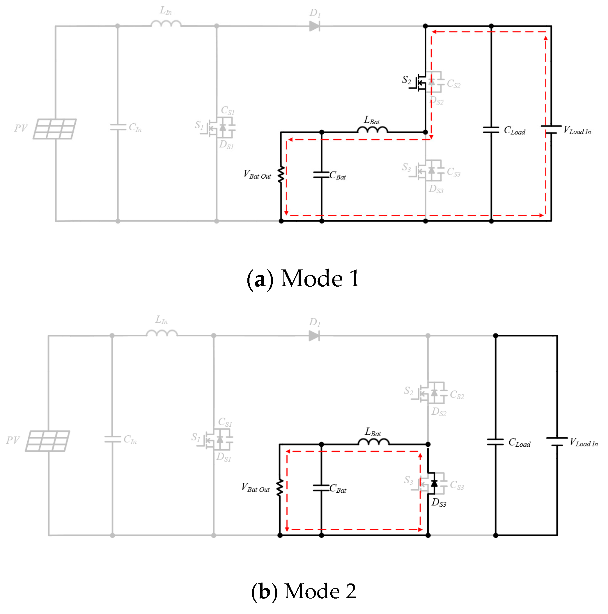
When t = t0, S2 is turned on, S1 and S3 are turned off, and D1 is turned off. Figure 7a presents the current flow direction. In this mode, the ES bus is used to store energy in the inductor LBat.
b.
Mode 2 [t1t < t2]
When t = t1, S1 and S3 are continuously turned off and S2 and D1 are turned off. Figure 7b displays the current flow direction. In this mode, the body diode of the switch S3 is turned on, and the capacitor CBat and inductor LBat release energy. The capacitor CBat and inductor LBat provide the energy at the output terminal of the energy storage battery.
C.
Stage 3: Storage battery provides energy to ES bus and charge the ES battery
When the energy supplied by the PV modules is insufficient, the storage battery is independently stepped up to the ES bus to charge the ES battery. Figure 8 presents the waveforms for the operation of the main components in Stage 3.
a.
Mode 1 [t0t < t1]
When t = t0, S3 is turned on, S1 and S2 are turned off, and D1 is turned off. Figure 9a illustrates the current flow direction. In this mode, the storage battery is used to store energy in the inductor LBat. At this time, the energy of ES bus terminal is provided by CLoad.
b.
Mode 2 [t1t < t2]
When t = t1, S3 is turned off, S1 and S2 are turned off, and the body diode of S2 is turned on. Figure 9b displays the current flow direction. In this mode, the energy of the inductor LBat is provided to the ES bus, and the ES battery is charged by the body diode.

3. Operation Mode Conversion Analysis

In mode 1, when the main switch is turned off, the energy of LIn and PV is transferred to VLoad through the D1 diode. When the energy of LIn is completely discharged and the circuit reaches the fully cut-off state, the power conversion of mode 2 can be performed.
In mode 2, when the main switch is turned off, the energy of LBat is transferred to VBat via the body diode of S3. When the energy of LBat is completely discharged and the circuit reaches the fully cut-off state, the power conversion of mode 3 can be performed.
In mode 3, when the main switch is turned off, the energy of LBat and VBat is transferred to VLoad via the body diode of S2. When the energy of LBat is completely discharged and the circuit reaches the fully cut-off state, it can go back to mode 2. Due to the simple circuit structure, the impact on transient energy conversion is small.

4. Steady-State Analysis

This section presents the mathematical derivation of the voltage conversion ratio and voltage stress of the components. First, the following assumptions can be made to simplify the analysis:
(1)
All components in the proposed topology are ideal components.
(2)
The capacitance is sufficiently large to maintain a constant voltage.
(3)
The system operates in a continuous conduction mode.

4.1. Voltage Conversion Ratio

Stage 1 is derived such that when PV energy is available, the PV module is stepped up to the ES bus to charge the ES battery. When the switch S1 is turned on, the voltage on the magnetizing inductance LIn can be expressed as follows:
V L I n = L I n d i L I n d t = V i
Because the rate of change of the inductor current is constant, when the switch is turned off, the current increases linearly with time. The change in the inductor current over time can be calculated as follows:
Δ i L I n Δ t = Δ i L I n D T = V i L I n
ΔiLIn can be expressed as shown in Equation (3) when the switch is turned off:
( Δ i L I n ) c l o s e d = V i D T L I n
When S1 is turned off (Figure 5), the inductor current does not change instantly, and the diode is turned on to provide the flow direction of the inductor current. If the output VCLoad is constant, the voltage across the inductor can be expressed as follows:
V L I n = ( V i V C L o a d ) = L I n d i L I n d t
( V i V C L o a d ) L I n = d i L I n d t
The rate of change of the inductor current is constant. The current changes linearly with time when the switch is turned off, and the change of the inductor current over time can be expressed as follows:
Δ i L I n Δ t = Δ i L I n ( 1 D ) T = ( V i V C L o a d ) L I n
( Δ i L I n ) o p e n = ( V i V C L o a d ) ( 1 D ) T L I n
According to the principle of voltage–second balance, the change of the inductor current must be zero under steady-state operation:
( Δ i L I n ) c l o s e d + ( Δ i L I n ) o p e n = 0
V i D T L I n + ( V i V C L o a d ) ( 1 D ) T L I n = 0
VCLoad is expressed as follows:
V i ( D + 1 D ) V C L o a d ( 1 D ) = 0
V C L o a d = V i 1 D
G V o = V C L o a d V i = 1 1 D
Mode 2 is derived when the energy at the ES load bus is sufficient. The voltage of the ES load bus is stepped down to charge the battery. When the switch is turned off (Figure 7), the diode is reverse biased, and the voltage across the inductor can be expressed as follows:
V L b a t = V C L o a d V B a t = L B a t d i L B a t d t
Δ i L B a t Δ t = ( V C L o a d V B a t ) L B a t
Because the differential value of the current is a positive constant, the current increases linearly with time:
Δ i L B a t Δ t = Δ i L B a t D T = ( V C L o a d V B a t ) L B a t
( Δ i L B a t ) c l o s e d = ( V C L o a d V B a t L B a t ) D T
When the switch S2 is turned off (Figure 7), the diode is forward biased to provide the flow direction of the inductor current. The voltage across the inductor is presented as follows:
V L b a t = V C L o a d = L B a t d i L B a t d t
d i L B a t d t = V B a t L B a t
Because the differential value of the current is a negative constant, the current decreases linearly with time:
Δ i L B a t Δ t = Δ i L B a t ( 1 D ) T = V B a t L B a t
( Δ i L B a t ) o p e n = ( V B a t L B a t ) ( 1 D ) T
According to the principle of voltage–second balance, the change of the inductor current within a cycle must be zero under steady-state operation:
( Δ i L B a t ) c l o s e d + ( Δ i L B a t ) o p e n = 0
( V C L o a d V B a t L B a t ) D T ( V B a t L B a t ) ( 1 D ) T = 0
VBat is:
V B a t = V C L o a t D
G V o = V B a t V C L o a d = D
Mode 3 is derived when the energy storage battery has sufficient power but no PV energy. The energy storage battery provides energy to the ES load bus and charges the ES battery. When the switch is turned off (Figure 9), the diode is reverse biased. According to Kirchhoff’s voltage law, VLBat can be presented as follows:
V L B a t = L B a t d i L B a t d t = V B a t
Because the rate of change of the inductor current is constant, the current increases linearly with time. The change of the inductor current over time can be calculated as follows:
Δ i L B a t Δ t = Δ i L B a t D T = V B a t L B a t
ΔiLBat is presented in Equation (27) when the switch is turned off:
( Δ i L B a t ) c l o s e d = V B a t D T L B a t
When S1 is turned off (Figure 9), the inductor current does not change instantaneously; therefore, the diode is forward biased to provide the flow direction of the inductor current. Assuming that the output VCLoad is a fixed constant, the voltage across the inductor can be expressed as follows:
V L B a t = ( V B a t V C L o a d ) = L B a t d i L B a t d t
( V B a t V C L o a d ) L B a t = d i L B a t d t
The rate of change of the inductor current is constant; therefore, the current changes linearly with time. When the switch is turned off, the change of the inductor current over time can be expressed as follows:
Δ i L B a t Δ t = Δ i L B a t ( 1 D ) T = ( V i V C L o a d ) L B a t
( Δ i L B a t ) o p e n = ( V B a t V C L o a d ) ( 1 D ) T L B a t
According to the principle of voltage–second balance, the change of the inductor current must be zero under steady-state operation:
( Δ i L B a t ) c l o s e d + ( Δ i L B a t ) o p e n = 0
V B a t D T L B a t + ( V B a t V C L o a d ) ( 1 D ) T L B a t = 0
VCLoad is:
V B a t ( D + 1 D ) V C L o a d ( 1 D ) = 0
V C L o a d = V B a t 1 D
G V o = V C L o a d V B a t = 1 1 D

4.2. Voltage Stress of Components

The voltage stress of each component can be derived by analyzing the components’ operation in the ON and OFF states.
The voltage stress of S1 in the ON state in Mode 1 can be determined as presented in Figure 5a, and the corresponding switching stress can be expressed as follows:
V i V L I n =   0
Therefore, the voltage stress of S1 can be derived as follows:
V S 1 =           1           1 D V i
The voltage stress of S2 in the OFF state in Mode 2 can be determined as illustrated in Figure 7b, and the corresponding switching stress can be presented as follows:
V S 2 = V L o a d
The voltage stress of S3 in the ON state in Mode 3 can be determined as displayed in Figure 9a, and the corresponding switching stress can be expressed as follows:
V B a t V L B a t =   0
Therefore, the voltage stress of S3 can be derived as follows:
V S 3 =           1           1 D V B a t
The voltage stress of the diode D1 in the ON state in Mode 1 can be determined as shown in Figure 5a. The corresponding diode stress is the voltage across the ES load bus.
V D 1 = V L o a d
The voltage stress of input capacitor CIn is VIn:
V C I n = V I n
The voltage stress of the output capacitor CLoad is VLoad:
V C L o a d = V L o a d
The voltage stress of the output capacitor CBat is VBat:
V C B a t = V B a t

5. Experimental Results and Analysis

Table 1 presents the electrical specifications and component parameters of the proposed nonisolated three-port bidirectional dc/dc converter.
Figure 10, Figure 11 and Figure 12 illustrate the efficiency curves obtained for the three operating modes of the proposed converter. As presented in Figure 10, in Mode 1, the efficiency was observed to be 97.45% under light-load operation (100 W), 95.8% under half-load operation (200 W), and 92.4% under full-load operation (400 W). The highest efficiency attained was 97.5% when the output power was 50 W. As displayed in Figure 11, in Mode 2, the highest efficiency was 92% under full-load operation (60 W), and the efficiency was observed to be 89.7% under half-load operation (30 W). Furthermore, in Mode 3, the efficiency levels were determined to be 97.7%, 97.4%, and 96.6% under light-load (29 W), half-load (60 W), and full-load (120 W) operation, respectively (Figure 12).
Figure 13 presents the voltage and current waveforms measured in Mode 1 at 100 W (light load) for S1 and IDS1. The duty cycle, input voltage, output voltage, input current, and output current of S1 were 55.3%, 24 V, 58 V, 4.3 A, and 1.72 A, respectively. Additionally, the voltage stress of S1 was 90 V, and the input current of LIn was 4.3 A.
Figure 14 presents the voltage and current waveforms measured in Mode 1 at 200 W (half load). The duty cycle, input voltage, output voltage, input current, and output current of S1 were 55.8%, 24 V, 58 V, 8.7 A, and 3.44 A, respectively. The voltage stress of S1 was 90 V, and the input current of LIn was 8.7 A (Figure 14a). Figure 14b shows the voltage and current waveforms of battery and output load operated under half load.
Figure 15 shows the voltage and current waveforms measured in Mode 1 at 400 W (full load). The duty cycle, input voltage, output voltage, input current, and output current of S1 were 57.8%, 24 V, 58 V, 18.4 A, and 6.9 A, respectively. The voltage stress of S1 was 90 V, and the input current of LIn was 18.4 A (Figure 15a). Figure 15b shows the voltage and current waveforms of battery and output load operated under full load.
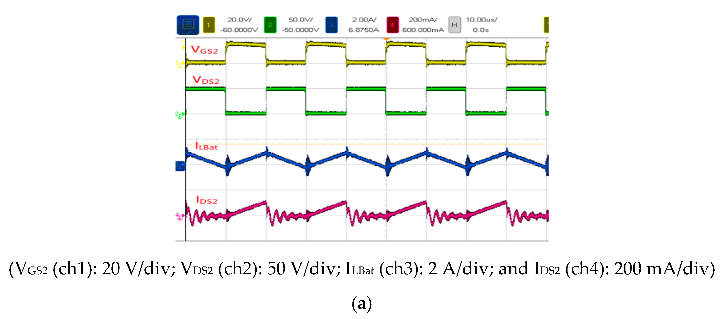
Figure 16 displays the voltage and current waveforms measured in Mode 2 at 14 W (light load) for IDS2 and S2. The duty cycle, input voltage, output voltage, input current, and output current of S2 were 41%, 58 V, 29.1 V, 0.3 A, and 0.5 A, respectively. The voltage stress of S2 was 50 V, and the battery inductance LBat current was 0.5 A.
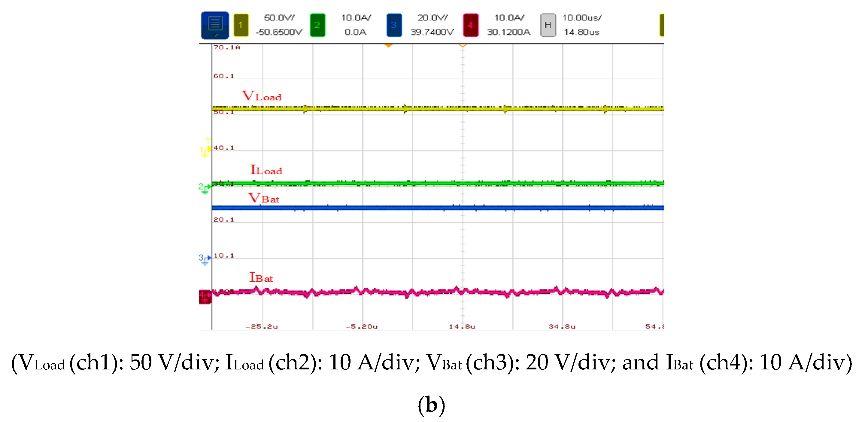
Figure 17 illustrates the voltage and current waveforms measured in Mode 2 at 30 W (half load). The duty cycle, input voltage, output voltage, input current, and output current of S2 were 46. 6%, 58 V, 29 V, 0.53 A, and 0.95 A, respectively. The voltage stress of S2 was 50 V, and the battery inductance LBat current was 0.95 A (Figure 17a). Figure 17b shows the voltage and current waveforms of battery and output load operated under half load.
Figure 18 presents the voltage and current waveforms measured in Mode 2 at 60 W (full load). The duty cycle, input voltage, output voltage, input current, and output current of S2 were 47.3%, 58 V, 29.1 V, 1.1 A, and 1.9 A, respectively. Moreover, the voltage stress of S2 was 50 V, and the battery inductance LBat current was 1.9 A (Figure 18a). Figure 18b shows the voltage and current waveforms of battery and output load operated under full load.
Figure 19 presents the voltage and current waveforms measured in Mode 3 at 30 W (light load). The duty cycle, input voltage, output voltage, input current, and output current of S3 were 56.8%, 24 V, 59 V, 1.26 A, and 0.5 A, respectively (Figure 19a). The voltage stress of S3 was 90 V, and the voltage stress of S2 was 50 V; the current waveform of IDS3 is also displayed in the figure. Figure 19b shows the voltage stress of S3 to be 90 V and the voltage stress of S2 to be 50 V; the current waveform of battery inductance LBat is also displayed in the figure.
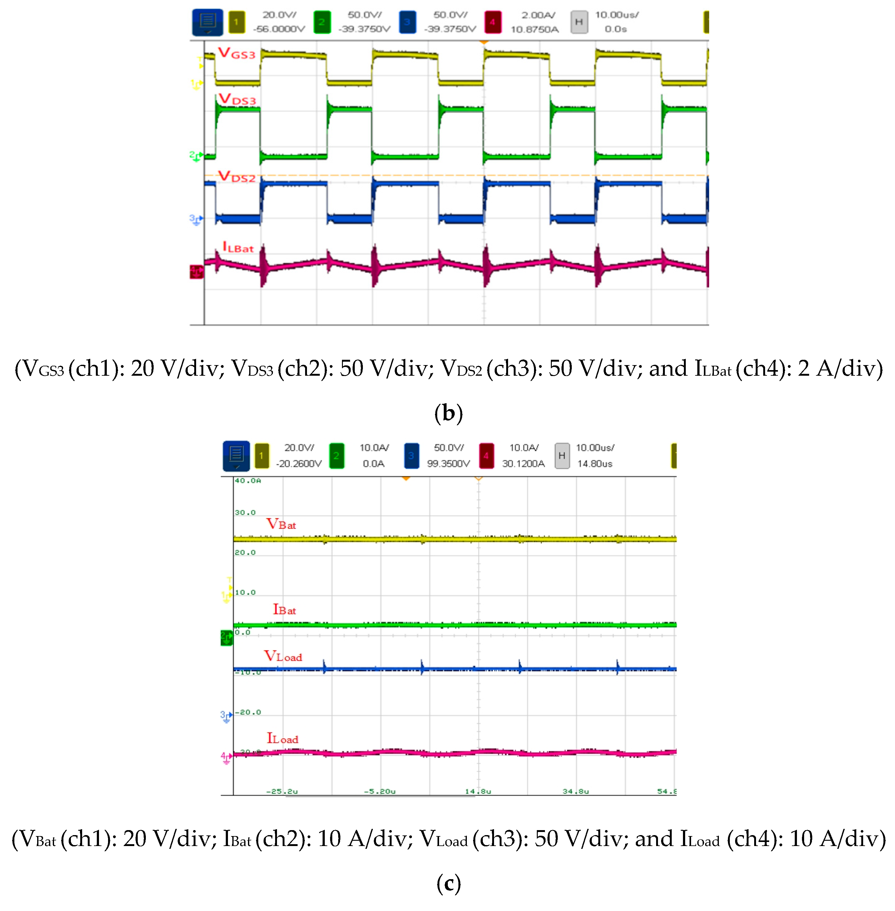
Figure 20 shows the voltage and current waveforms measured in Mode 3 at 60 W (half load). The duty cycle, input voltage, output voltage, input current, and output current of S2 were 58%, 24 V, 59 V, 2.5 A, and 1 A, respectively (Figure 20a). The voltage stress levels of S3 and S2 were 90 and 50 V, respectively (Figure 20b). The control waveform of S3 and current waveform of the battery inductance LBat are presented in the figures. Figure 20c shows the voltage and current waveforms of battery and output load operated under half load.
Figure 21 displays the voltage and current waveforms measured in Mode 3 at 120 W (full load). The duty cycle, input voltage, output voltage, input current, and output current of S3 were 57%, 24 V, 59 V, 5.1 A, and 2 A, respectively (Figure 21a). The voltage stress of S3 was 90 V, and that of S2 was 50 V; the current waveform IDS3 of S3 was obtained. Furthermore, the voltage stress levels of S3 and S2 were 90 and 50 V, respectively (Figure 21b); Figure 21b indicates the current waveform of the battery inductance LBat. Figure 21c shows the voltage and current waveforms of battery and output load operated under full load.
In addition, in order to verify the characteristics of the dynamic response of the proposed converter, Figure 22a,c respectively shows the measurement waveforms of the three operating modes under load variation from half load to full load, and then full load to half load.
It can be seen from these figures that the proposed DC/DC converter has excellent dynamic response. The load voltage (Vload) and battery voltage (Vbat) are minimally affected by load variation.
Figure 23 illustrates the physical circuit of the proposed three-terminal bidirectional converter.
To demonstrate that the proposed converter exhibits higher feasibility, higher efficiency, and a lower component count than do existing converters, this study selected converters proposed in the literature for comparison. Table 2 presents the comparison of the proposed converter with bidirectional converters in the literature. All converters involve nonisolated topologies. The number of components, input and output voltages, output power, efficiency, and number of operating modes are also presented in this table.
Figure 24 illustrates an efficiency comparison between the proposed converter and those in [25,26,27] under step-up operation. The proposed converter is shown to exhibit the highest efficiency.
Figure 25 displays an efficiency comparison between the proposed converter and those in [25,26,27] under step-down operation. The efficiency of the proposed converter is shown to be considerably higher than that of the converters in [25] and [27] but lower than that of the converter in [26].
Table 3 presents a comparison of the proposed converter with those in [28,29,30]. The proposed converter is shown to exhibit the highest efficiency and lowest component count. Figure 26 illustrates an efficiency comparison between the proposed converter and those in [28,29,30] under step-up operation. The figure indicates that the efficiency of the proposed converter is higher than that of the converters in [28,29,30].
On the basis of the preceding comparisons, the proposed converter exhibits higher efficiency and feasibility as well as a lower number of components and cost than do converters in the literature.

6. Conclusions

This paper presents a three-port bidirectional dc/dc converter for PV ES charging stations and provides a theoretical analysis of the converter under steady-state operation. Results obtained from experimental tests of the converter are also presented. The converter operates in PV step-up, battery step-up, and ES load bus step-down modes, reflecting the high functionality of the circuit. The proposed converter offers the advantages of high efficiency, three simple operating modes, small system size, low switch voltage stress and low cost. It can indeed achieve practical applications. Finally, a 400-W/60-W/120-W three-port bidirectional converter was implemented to verify its feasibility and practicability. The highest efficiency levels of the proposed converter under PV step-up, battery step-up, and step-down operation were 97.5%, 97.7%, and 92%, respectively.

Author Contributions

The contributions of Y.-E.W. include Conceptualization, methodology, original draft preparation, review and editing. The contributions of X.-Y.L. include validation, formal analysis and investigation. All authors have read and agreed to the published version of the manuscript.

Funding

This research received no external funding.

Conflicts of Interest

The authors declare no conflict of interest.

References

  1. Taiwan’s Response to the Climate Change Framework Convention Information Network. Available online: http://www.tri.org.tw/unfccc/ (accessed on 10 September 2019).
  2. Ministry of Economic Affairs. Available online: https://www.re.org.tw/default.aspx (accessed on 12 September 2019).
  3. Boujelben, N.; Masmoudi, F.; Djemel, M.; Derbel, N. Design and comparison of quadratic boost and double cascade boost converters with boost converter. In Proceedings of the 2017 14th International Multi-Conference on Systems, Signals & Devices (SSD), Marrakech, Morocco, 28–31 March 2017; pp. 245–252. [Google Scholar]
  4. Ismail, E.H.; Al-Saffar, M.A.; Sabzali, A.J. High Conversion Ratio DC–DC Converters with Reduced Switch Stress. IEEE Trans. Circuits Syst. I Regul. Studys 2008, 55, 2139–2151. [Google Scholar] [CrossRef]
  5. Pressman, A.I.; Billings, K.; Morey, T. Switching Power Supply Design, 3rd ed.; Quanhua Book Company: Taipei, Taiwan, 2012. [Google Scholar]
  6. Zhao, Q.; Lee, F.C. High performance coupled-inductor DC-DC converters. In Proceedings of the Eighteenth Annual IEEE Applied Power Electronics Conference and Exposition, 2003. APEC ’03, Miami Beach, FL, USA, 9–13 February 2003; pp. 109–113. [Google Scholar]
  7. Huber, L.; Jovanovic, M.M. A design approach for server power supplies for networking applications. In Proceedings of the APEC 2000 Fifteenth Annual IEEE Applied Power Electronics Conference and Exposition (Cat. No.00CH37058), New Orleans, LA, USA, 6–10 February 2000; pp. 1163–1169. [Google Scholar]
  8. Feng, X.; Liu, J.; Lee, F.C. Impedance specifications for stable DC distributed power systems. IEEE Trans. Power Electron. 2002, 17, 157–162. [Google Scholar] [CrossRef]
  9. Wu, T.F.; Yu, T.-H. Unified approach to developing single-stage power converters. IEEE Trans. Aerosp. Electron. Syst. 1998, 34, 211–223. [Google Scholar]
  10. Luo, F.L.; Ye, H. Positive output super-lift converters. IEEE Trans. Power Electron. 2003, 18, 105–113. [Google Scholar]
  11. Zhao, Q.; Tao, F.; Lee, F.C. A front-end DC/DC converter for network server applications. In Proceedings of the 2001 IEEE 32nd Annual Power Electronics Specialists Conference (IEEE Cat. No.01CH37230), Vancouver, BC, Canada, 17–21 June 2001; pp. 1535–1539. [Google Scholar]
  12. Chen, F.; Amirahmadi, A.; Batarseh, I. Zero voltage switching Forward-Flyback Converter with efficient active LC snubber circuit. In Proceedings of the 2014 IEEE Applied Power Electronics Conference and Exposition—APEC 2014, Fort Worth, TX, USA, 16–20 March 2014; pp. 2041–2047. [Google Scholar]
  13. EPARC. Power Electronics Review, 2nd ed.; Quanhua Book Company: Taipei, Taiwan, 2013. [Google Scholar]
  14. Hart, D.W. Power Electronics; Quanhua Book Company: Taipei, Taiwan, 2013. [Google Scholar]
  15. Jianhua, W.; Fanghua, Z.; Chunying, G.; Ran, C. Modeling and analysis of a buck/boost bidirectional converter with developed PWM switch model. In Proceedings of the 8th International Conference on Power Electronics—ECCE Asia, Jeju, Korea, 30 May–3 June 2011; pp. 705–711. [Google Scholar]
  16. Mohammadi, M.R.; Farzanehfard, H. A new bidirectional ZVS-PWM Cuk converter with active clamp. In Proceedings of the 2011 19th Iranian Conference on Electrical Engineering, Tehran, Iran, 17–19 May 2011; pp. 1–6. [Google Scholar]
  17. Dimna Denny, C.; Shahin, M. Analysis of bidirectional SEPIC/Zeta converter with coupled inductor. In Proceedings of the 2015 International Conference on Technological Advancements in Power and Energy (TAP Energy), Kollam, India, 24–26 June 2015; pp. 103–108. [Google Scholar]
  18. Song, Y.; Enjeti, P.N. A new soft switching technique for bi-directional power flow, full-bridge DC-DC converter. In Proceedings of the Conference Record of the 2002 IEEE Industry Applications Conference. 37th IAS Annual Meeting (Cat. No.02CH37344), Pittsburgh, PA, USA, 13–18 October 2002; pp. 2314–2319. [Google Scholar]
  19. Ma, Z.; Hu, R. Zero-voltage-switching condition of isolated-type symmetrical half-bridge bidirectional DC/DC converter. In Proceedings of the 2011 International Conference on Electrical and Control Engineering, Yichang, China, 16–18 September 2011; pp. 2347–2350. [Google Scholar]
  20. Duan, R.; Lee, J. High-efficiency bidirectional DC-DC converter with coupled inductor. IET Power Electron. 2012, 5, 115–123. [Google Scholar] [CrossRef]
  21. Wai, R.; Liaw, J. High-Efficiency-Isolated Single-Input Multiple-Output Bidirectional Converter. IEEE Trans. Power Electron. 2015, 30, 4914–4930. [Google Scholar] [CrossRef]
  22. Zhang, B.; Wang, P.; Bei, T.; Li, X.; Che, Y.; Wang, G. Novel topology and control of a non-isolated three port DC-DC converter for PV-battery power system. In Proceedings of the 2017 20th International Conference on Electrical Machines and Systems (ICEMS), Sydney, Australia, 11–14 August 2017; pp. 1–6. [Google Scholar]
  23. Li, W.; Xu, C.; Luo, H.; Hu, Y.; He, X.; Xia, C. Decoupling-Controlled Triport Composited DC/DC Converter for Multiple Energy Interface. IEEE Trans. Ind. Electron. 2015, 62, 4504–4513. [Google Scholar] [CrossRef]
  24. Hu, Y.; Xiao, W.; Cao, W.; Ji, B.; Morrow, D.J. Three-Port DC–DC Converter for Stand-Alone Photovoltaic Systems. IEEE Trans. Power Electron. 2015, 30, 3068–3076. [Google Scholar] [CrossRef] [Green Version]
  25. Das, P.; Mousavi, S.A.; Moschopoulos, G. Analysis and Design of a Nonisolated Bidirectional ZVS-PWM DC–DC Converter with Coupled Inductors. IEEE Trans. Power Electron. 2010, 25, 2630–2641. [Google Scholar] [CrossRef]
  26. Do, H. Nonisolated Bidirectional Zero-Voltage-Switching DC–DC Converter. IEEE Trans. Power Electron. 2011, 26, 2563–2569. [Google Scholar] [CrossRef]
  27. Liang, T.; Lee, J. Novel High-Conversion-Ratio High-Efficiency Isolated Bidirectional DC–DC Converte. IEEE Trans. Ind. Electron. 2015, 62, 4492–4503. [Google Scholar] [CrossRef]
  28. Cheng, T.; Lu, D.D.; Qin, L. Non-Isolated Single-Inductor DC/DC Converter with Fully Reconfigurable Structure for Renewable Energy Applications. IEEE Trans. Circuits Syst. Ii Express Briefs 2018, 65, 351–355. [Google Scholar] [CrossRef]
  29. Zeng, J.; Qiao, W.; Qu, L. An Isolated Three-Port Bidirectional DC–DC Converter for Photovoltaic Systems with Energy Storage. IEEE Trans. Ind. Appl. 2015, 51, 3493–3503. [Google Scholar] [CrossRef]
  30. Uno, M.; Oyama, R.; Sugiyama, K. Partially Isolated Single-Magnetic Multiport Converter Based on Integration of Series-Resonant Converter and Bidirectional PWM Converter. IEEE Trans. Power Electron. 2018, 33, 9575–9587. [Google Scholar] [CrossRef]
  31. Wu, Y.-E.; Chiu, P.-N. A High-Efficiency Isolated-Type Three-Port Bidirectional DC/DC Converter for Photovoltaic Systems. Energies 2017, 10, 434. [Google Scholar] [CrossRef] [Green Version]
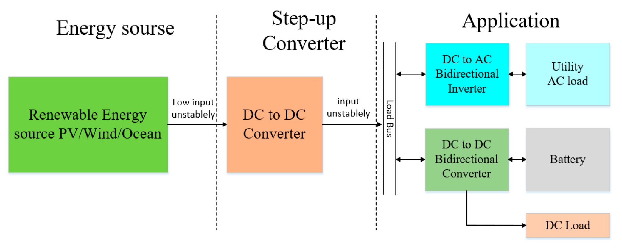
Figure 1. Block diagram of green energy application.
Electronics 09 01741 g001
Figure 2. Three-port bidirectional converter application.
Electronics 09 01741 g002
Figure 3. Proposed non-isolated three-port bidirectional dc/dc converter.
Electronics 09 01741 g003
Figure 4. Waveforms obtained for the operation of the main components in Stage 1.
Electronics 09 01741 g004
Figure 5. Circuit operation in each mode in Stage 1: (a) Mode 1 and (b) Mode 2.
Electronics 09 01741 g005
Figure 6. Waveforms obtained for the operation of main components in Stage 2.
Electronics 09 01741 g006
Figure 7. Circuit operation in each mode in Stage 2: Modes (a) 1 and (b) 2.
Electronics 09 01741 g007
Figure 8. Waveforms obtained for the operation of the main components in Stage 3.
Electronics 09 01741 g008
Figure 9. Circuit operation in each mode in Stage 3: Modes (a) 1 and (b) 2.
Electronics 09 01741 g009
Figure 10. Efficiency curves for the proposed converter in Mode 1 operation.
Electronics 09 01741 g010
Figure 11. Efficiency curves for the proposed converter in Mode 2 operation.
Electronics 09 01741 g011
Figure 12. Efficiency curves for the proposed converter in Mode 3 operation.
Electronics 09 01741 g012
Figure 13. Voltage and current waveforms measured in Mode 1 at 100 W (light load).
Electronics 09 01741 g013
Figure 14. Voltage and current waveforms measured in Mode 1 at 200 W (half load).
Electronics 09 01741 g014
Figure 15. Voltage and current waveforms measured in Mode 1 at 400 W (full load).
Electronics 09 01741 g015aElectronics 09 01741 g015b
Figure 16. Voltage and current waveforms of Mode 2 at 14 W (light load).
Electronics 09 01741 g016
Figure 17. Voltage and current waveforms measured in Mode 2 at 30 W (half load).
Electronics 09 01741 g017aElectronics 09 01741 g017b
Figure 18. Voltage and current waveforms measured in Mode 2 at 60 W (full load).
Electronics 09 01741 g018
Figure 19. Voltage and current waveforms measured in Mode 3 at 30 W (light load).
Electronics 09 01741 g019
Figure 20. Voltage and current waveforms measured in Mode 3 at 60 W (half load).
Electronics 09 01741 g020aElectronics 09 01741 g020b
Figure 21. Voltage and current waveforms measured in Mode 3 at 120 W (full load).
Electronics 09 01741 g021aElectronics 09 01741 g021b
Figure 22. Measured waveforms of the three operating modes under load changes, (a) Mode 1, (b) Mode 2, and (c) Mode 3.
Electronics 09 01741 g022aElectronics 09 01741 g022b
Figure 23. Proposed three-port bidirectional dc/dc converter.
Electronics 09 01741 g023
Figure 24. Efficiency comparison between the proposed converter and those in [25,26,27] under step-up operation.
Electronics 09 01741 g024
Figure 25. Efficiency comparison between the proposed converter and those in [25,26,27] under step-down operation.
Electronics 09 01741 g025
Figure 26. Efficiency comparison between the proposed converter and those in [28,29,30] under step-up operation.
Electronics 09 01741 g026
Table 1. Electrical Specifications and Component Parameters of the Proposed Converter.
ParameterSpecification
Input PV voltage Vin24 V
Battery voltage VBat24 V
Load bus voltage VLoad48 V
Maximus output battery power60 W
Maximus output load bus power400 W
Switching frequency fs50 kHz
ComponentModelSpecification
S1, S2, S3IRFP4332250 V/57 A
D1MBR40200200 V/40 A
CInElectrolytic Capacitor100 μF/100 V
CLoad, CBatElectrolytic Capacitor470 μF/450 V
LIn, LBatMPP Ring Core100 μH
Table 2. Comparison of the Proposed Converter with Bidirectional Converters in the Literature.
ReferencesProposed ConverterReference [25]Reference [26]Reference [27]
TopologyNon-IsolatedNon-IsolatedNon-IsolatedNon-Isolated
Input Voltage24 V24–30 V48 V24 V
Output Voltage58 V200 V120 V200 V
Output Power120 W200 W100 W200 W
Number of Switches3324
Number of Diodes1000
Number of Inductors2212
Number of Capacitors3123
Number of Coupled-inductors0111
Output Terminal2222
Maximum Conversion Efficiency (Step up/Step down)96.6%/92%91.5%/91%95.6%/95.3%96%/95%
CostLowHighMediumHigh
Converter Operational Mode2222
Table 3. Comparison of the Proposed Converter with Other Three-Port Converters.
ReferencesProposed ConverterReference [28]Reference [29]Reference [30]
TopologyNon-IsolatedNon-IsolatedIsolatedIsolated
Input Voltage24 V17 V16 V36 V
Battery Voltage28 V36 V7.5 V16 V
Load Bus Voltage58 V24 V50 V45 V
Output Power400 W500 W120 W150 W
Number of Switch3432
Number of Diode1544
Number of Transformer0011
Number of Inductor2120
Number of Capacitor3354
Transformer Turns005:149:25
Output Terminal2222
Maximum Conversion Efficiency (Step-up)96.6%85%94.5%87.4%
Converter Mode3733
Publisher’s Note: MDPI stays neutral with regard to jurisdictional claims in published maps and institutional affiliations.