1. Introduction
High torque capability per volume is the most desired performance characteristics among electrical machine designers today, of which permanent magnet (PM) machines are prioritized candidates. However, the need to design and continuously highlight alternative non-PM machine topologies has been a recent norm, given the rare-earth PM commodity price issues which surfaced between 2011 and 2012 [
1].
Among the available high torque density machines are the recently emerged flux modulation (FM) machines, which operate on the so-called FM principle, i.e., the presence of a flux modulator ensures that a magnetic gearing effect is always propagated [
2]. Whereby majority of FM machines are PM-based, the possibility to implement them as non-PM machines, using purely field-winding coils, is very established, although it goes without saying that the torque density could be less appealing. Notwithstanding, wound-field flux modulation machines (WF-FMMs) such as the wound-field flux switching machine (WF-FSM) and the DC-excited Vernier reluctance machine (DC-VRM) are very attractive in that they are non-PM variants with mainly stator-mounted coils, which means they are neither threatened by demagnetization nor do they need slip rings and brushes unlike in classical wound-rotor synchronous machines. Moreover, their robust rotor and concentrated winding structures are further impetus to their easy manufacturability, high reliability and wide utility [
3,
4,
5].
However, one of the main challenges with WF-FMMs is in terms of high magnetic saturation which limits their overload capability. Due to deep saturation and high armature reaction effects when operating in overload mode, the inductance prediction is affected, leading to distinct self- and mutual-components during excitation of the field and/or armature windings [
6,
7,
8]. Previous studies, which attempted the determination of the inductance components in PM-FSM are very basic and do not elucidate on the mutual (cross-coupling) components [
9,
10]. Similarly, one study which looked at the torque ripple analysis in DC-VRM attributed to the self- and mutual-inductances in the evaluation of the electromagnetic torque, but fell short on how to estimate them [
11]. The torque separation of the hybrid-excited (HE)-FSM, as proposed using the frozen permeability method (FPM), is done only with reference to the self-inductances [
12]. However, it has been shown, even for wound-rotor synchronous motors that the cross-coupling inductances can be severe under saturation, and do affect the effective torque, among others [
8,
13]. Therefore, the existence and prominence of the cross-coupling inductance in WF-FMMs, where both the field and armature windings are collocated on the same core, is expected to be much more, leading to certain defects in machine performance such as in torque and power factor calculations.
In this paper, an analytic cum numerical procedure based on the FPM is developed in the study to accurately estimate the self- and mutual-inductance parameters of the two variants of the WF-FMM i.e., WF-FSM and DC-VRM, while also evaluating the effects on machine performance, especially under deep saturation. The complete characterization of the inductance parameters in these machines helps in the accurate design, performance prediction, fault-tolerance analysis and control of these machines, while providing proper estimation on errors being incurred due to the ignorance of the cross-coupling inductances in the performance analysis of the benchmark WF-FMMs.
In the following section, the proposed FPM modeling procedure is fully derived for the desired performance variables. This is then followed up with simulated results and discussion from 2D finite element method (FEM) in
Section 3, and based on some design benchmarks of the proposed machines. It is also in this section where the validation of the proposed FPM modeling using a commercial FEM software package is given. Lastly in
Section 4, some conclusions are drawn.
2. Proposed Modeling
The steady-state FEM modeling approach which uses the decomposed total flux linkages of the machine is proposed. The flux linkages are net flux linkages produced by the currents from which parameters of the machine are determined, which guarantees accuracy of the modeling approach. Additionally, it is not only the non-linear operating region of the machine dealt with, but also the cross-magnetization and saturation saliency effects on the machine incorporating high-order harmonic and leakage fluxes produced by the winding and slotted air gap. With these decomposed total flux linkages, the inductance and performance variables of the machine can be calculated accurately.
In the case of a current-fed machine, the FEM uses the magnetic vector potential approach to solve for the Maxwell equations that describe fields in the magneto-static problem given by
where
,
and
are magnetic flux density, magnetic field intensity and current density vectors, respectively. The latter is done by finding the vector potential (
) which satisfies
where
is the reluctivity of the material. In 2D problem applications,
and
of (
3) only have the z component. The total current flowing through a coil of surface area (
s) is calculated from
Utilizing Park’s transformation [
14] i.e., direct (d) and quadrature (q) axes rotating at electrical angular frequency (
) fixed on the rotor, for a given electrical rotor position (
), the current source (or stator) k
th phase is calculated as
where
m is the number of phases. The magnetic fields are then obtain, followed by the k
th phase flux linkages calculated as
where
ℓ is the machine length,
is the surface area of the j
th slot and
is the number of conductors in the j
th of the k
th phase. Additionally, utilizing Park’ transformation, the stator d (
) and q (
) axes total flux linkage components are calculated as
Taking
, the stator phases (i.e., 1, 2 and 3) and dq-axes relative positions of the current and flux linkage components are defined in
Figure 1 where
and
are current and flux linkage angles respectively. Thus, both current and flux linkage dq-axes components can be expressed in terms of their respective magnitudes (
I and
) and angles as
In general,
and
of (
7) depend on
,
,
(field current) and
such that
It is important to state that
(field current) and
are not given as variables of (
9) as the study in this paper is to show only the effect of the dq-axes currents (
8) on the inductances and performance of the machines.
In the case of the classical (conventional) synchronous machines with sine-distributed windings and no saturation,
and
can be represented by simple dq-axes inductance terms, from
Figure 1 in generator mode as [
15]
where the equivalent dq-axes inductances (
,
and
) are given by conventional calculated self-inductances (
,
and
) as
As stated in the introduction, due to deep saturation and high armature reaction effects when operating WF-FMMs in overload mode, the inductance prediction is affected, leading to distinct self- and mutual-components during double excitation. Hence, the model of (
10) is not complete. For a complete model, all the effects of saturation must be included, thus according to the complete model in [
13,
16], Equation (
11) is replaced by a simplified expression given as
In Equation (
12), the non-classical (actual) calculated inductances
and
are due to
and
, respectively,
are due to
and
,
and
are due to axes cross-coupling. Note, the error in inductances of (
12) are given by the terms in curl brackets. Only the accuracy to which these parameters are predicted will influence the accuracy of the rotor position estimation [
17,
18]. In addition, to solve for currents, given voltages are only accurate if the terms in curl brackets of (
12) are included. Thus, the calculation methodology of WF-FMM inductances is extremely critical. The latter is implemented using classical and non-classical numerical analysis methods.
In both classical and non-classical numerical methods of calculating inductances, any operating point is defined by exciting the machine with all currents (
,
and
). A non-linear magneto-static simulation is then performed. The latter is to obtain the total dq-axis flux linkages (
and
) of (
10). Thus, a non-linear solution is conducted with all
,
and
, resulting in all
m-phase currents given by (
5). The corresponding all
m-phase total flux linkages of (
6) are then calculated using the obtained solution for magnetic vector potential according to (
3), and dq-axes total flux linkages of (
10) are then calculated as
To determine the conventional calculated inductances of (
11) at an operating point defined in (
13), a single non-linear magneto-static simulation is performed. The non-linear solution is conducted by setting
and
to zero and having only
, to calculate the d-axis flux linkage (
) due to
current excitation i.e.,
in (
10). All
m-phase field flux linkages of (
6) are then calculated using the obtained solution for magnetic vector potential according to (
3), and the d-axis conventional flux linkage is then calculated as
In Equation (
14), the q-axis conventional calculated flux linkage
since classically, the field winding is assumed to be aligned with the d-axis and only generates d-axis flux. The conventional calculated inductances in (
12) are then determined from (
13) and (
14) as
The most optimal strategy to determine the actual inductances of (
12) at any operating point as defined in (
13) and still preserve all the information about saturation in the machine is by utilizing the proposed FPM [
13]. Using the FPM, the total flux linkages can be decomposed into components due to individual current excitations (i.e.,
or
and or
). Thus at a certain operating point set by all
,
and
currents (i.e., (
13)), a non-linear magneto-static simulation is performed in order to obtain the values of the permeabilities in the nodes of the FE mesh. The values of the obtained (i.e., frozen) permeabilities are then used to conduct three linear magneto-static simulations (i = 1, 2 and 3) to obtain dq-axes flux linkages (
and
) from which
,
,
,
,
and
of (
12) are determined. By freezing the permeabilities all inductances (i.e., self and mutual) can be computed with high precision [
19].
The first linear simulation (i = 1) is conducted by setting
and
to zero and having only
. All
m-phase flux linkages of (
6) are then calculated using the obtained solution for magnetic vector potential according to (
3), and dq-axes actual flux linkages are then calculated as
The saturated values
f-axis and the cross-axes inductances
and
in (
12) are respectively determined from
The second linear simulation (i
) is conducted with only
, while
and
are set to zero, resulting in all
m-phase currents of (
5) given by
The corresponding all
m-phase flux linkages are calculated using the obtained solution for magnetic vector potential, according to (
3), and the actual flux linkages
and
are calculated as in (
16). The saturated d-axis and cross-axes inductances
and
in (
12) are respectively determined from
The third linear simulation (i
) is conducted with only
, while
and
are set to zero, resulting in all
m-phase currents of (
5) given by
The corresponding all
m-phase flux linkages are calculated using the obtained solution for magnetic vector potential, according to (
3), and the actual flux linkages
and
are calculated as in (
16). The saturated d-axis and cross-axes inductances
and
are calculated as
It should be noted that the dq-axes non-linear magneto-static solution of (
13) is equal to the sum of the three respective individual linear magneto-static solution discussed in (
16)–(
21) i.e.,
For the WF-FMM performance, the variables discussed in this paper are defined as the saliency (
), and field (
) ratios, the electromagnetic torque (
) and the power factor (PF). The actual calculated inductances of (
17), (
19) and (
21) determined from the FPM are used in the calculation to give a better representation of the performance variables.
The saliency and field ratios are calculated as
The electromagnetic torque, generated by the interaction between the total current and flux linkage components is calculated by
where
Q is the rotor teeth number of the WF-FMM. Furthermore, to understand the effect of inductances on the torque, the torque of (
24), redefined as
is calculated using inductances where
In Equation (
25),
,
and
are the field, reluctance (saliency) and mutual torques, respectively.
In addition, knowing the stator phase resistance (
), the power factor is calculated from the scalar product of current and terminal voltage components, as
where
I is given in
Figure 1,
and
. The equivalent inductances in (
28) are of (
12). In addition, to understand the effect of the different inductances on the power factor, if
is ignored in (
28), then the power factor of (
27) is expressed by
In Equation (
29),
given in
Figure 1 is the magnitude of the dq-axes total flux linkages.
3. Simulation Results
An in-house static FEM software package which uses total flux linkages on the machine solution domain is utilized in the simulation results of both WF-FMMs [
20]. These total flux linkages are the net flux linkages which include high-order harmonics and leakage fluxes produced by the winding, slotted air gap and magnetic saturation. The latter is essential because a complete parameter prediction model of the machine is obtained.
Figure 2 shows optimized 15 kW WF-FMMs static 2D FEM developed models. The model meshes are carried out as user-controlled mesh. The flexible triangle nodes are used to create complex geometry triangular meshes in the solution domains.
Table 1 gives the specification of the two WF-FMMs shown in
Figure 2 used in the simulations described in
Section 2. A M400-50A lamination steel
curve is used. For the current-controlled machines at rated current magnitude, the different operating points are achieved by varying the current angle
, defined in
Figure 1 and expressed in (
8).
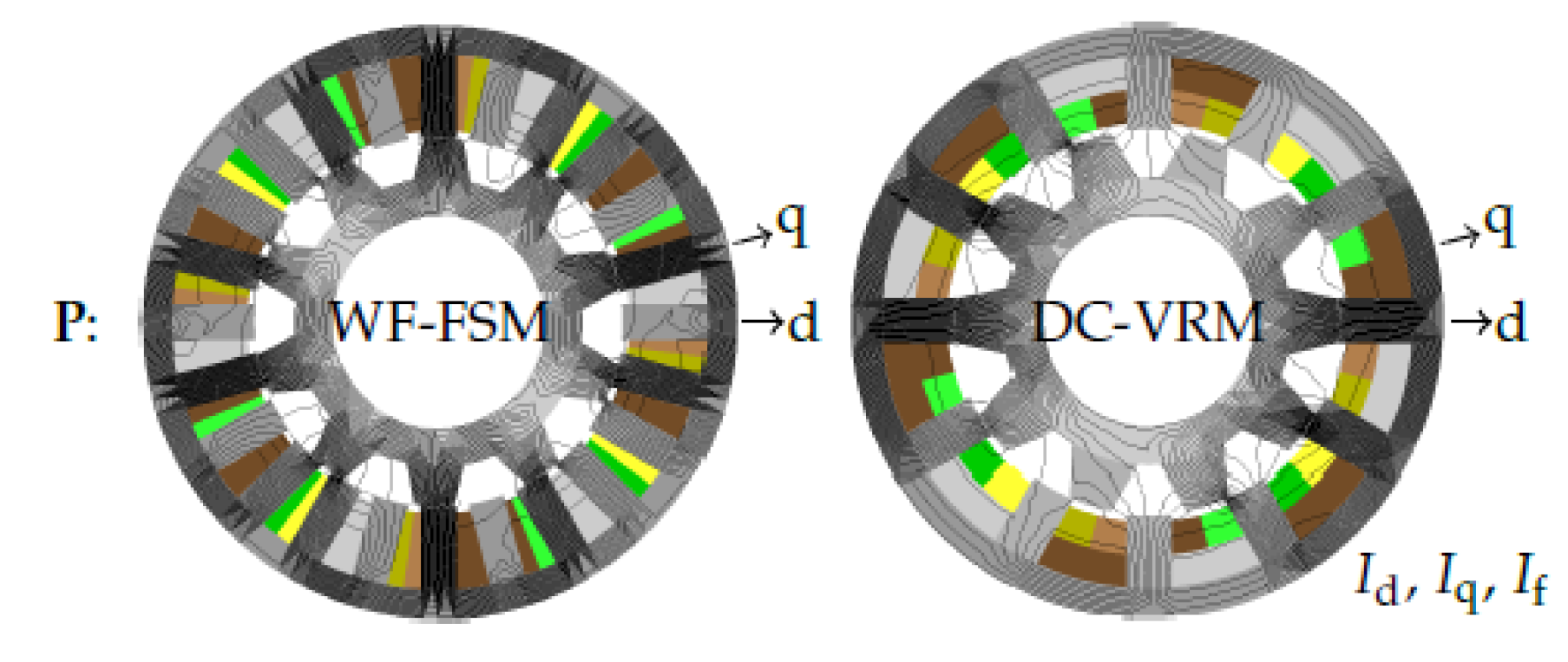
Figure 3 shows the field solution using the non-linear simulation on both WF-FSM and DC-VRM machines at an operating current angle of
, which is at or close to maximum torque. The field solution
P in
Figure 3 is a non-linear FEM solution with all currents excited, i.e.,
,
and
.
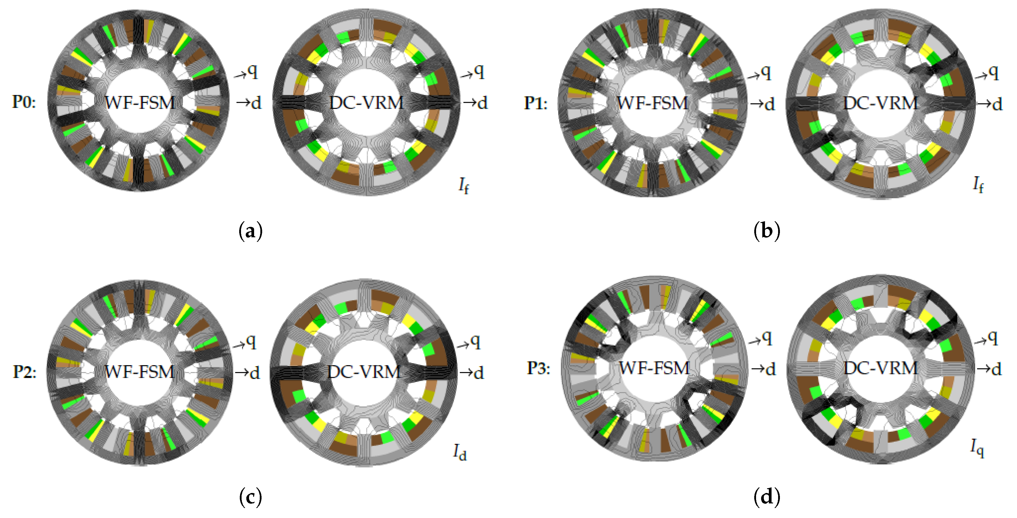
Figure 4 shows the field solutions using the conventional numerical method and the FPM on both the WF-FSM and DC-VRM machines at an operating defined in
Figure 3. For the conventional method
P in
Figure 3 is followed by a non-linear FEM solution with field excitation, i.e.,
P0 of
Figure 4a with only
current. For the FPM, freezing the element permeabilities of
P in the
Figure 3 solution is followed by three corresponding linear FEM solutions with single excitations, i.e.,
P1 of
Figure 4b with only
current,
P2 of
Figure 4c with only
current, and
P3 of
Figure 4d with only
current.
The non-linear field solution
P is used in the calculation of the total flux linkages [
,
] of (
13). The corresponding non-linear
P0 and linear
P1,
P2 and
P3 field solutions are used in the calculation of the flux linkages [
] of (
14) and [
,
], [
,
] and [
,
] as of (
16), respectively. These resulting flux linkages are then used for the calculation of inductances [
,
,
] according to (
15) and [
,
], [
,
] and [
,
] according to (
17), (
19) and (
21), respectively.
It is important to state that (
22) is used to check if the FPM procedure using the FEM works correctly. The correct working can also be observed in
Figure 3 and
Figure 4. At solution
P of
Figure 3, the field line distribution is clearly dense in both excited axes. The single excited field solutions
P0–
P3 of
Figure 4a–d show less dense field line distributions and are aligned to the excited axes.
Figure 5,
Figure 6,
Figure 7,
Figure 8,
Figure 9 and
Figure 10 show the simulated average parameter results at different operating points i.e.,
solved at each rotor position using the analysis described in
Section 2 by calculating the mean value of all rotor position. In
Figure 6,
is the average magnetic stress tensor torque, which is shown to be the same value to the inductance calculated torque of (
25). In addition, during the simulations it was found that always
; hence, in
Figure 5 the inductance
.
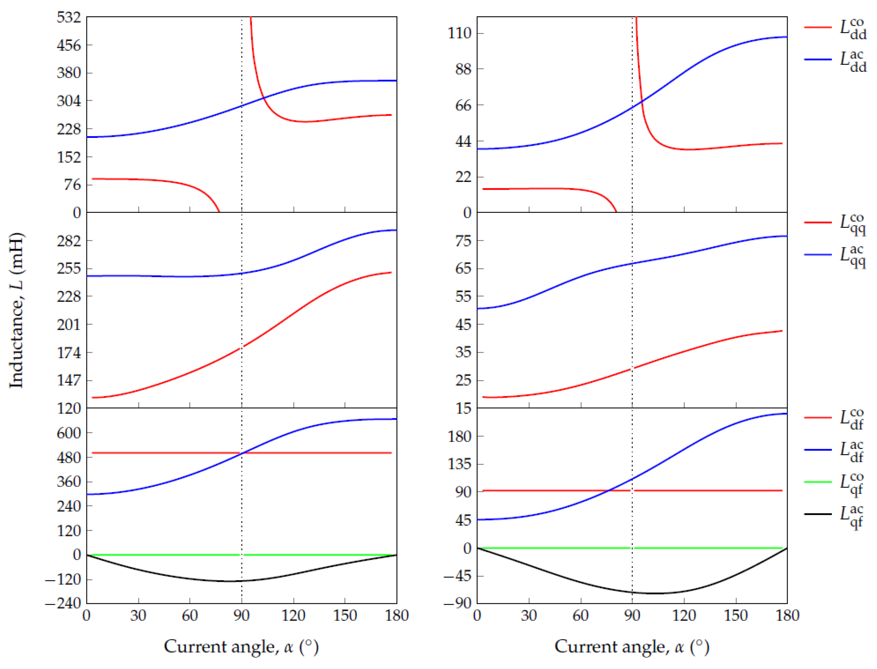
The actual calculated inductances of (
17), (
19) and (
21) are shown in
Figure 5. It is evident that saturation has a significant effect on the dq magnetic axes of both WF-FSM and DC-VRM machines. As
increases, the d-axis comes out of saturation, especially for the DC-VRM. Accordingly,
and
increase as shown in
Figure 5. At lower values of
, the d-axis inductance is not considerably affected by cross-coupling i.e.,
L ≈ 0. As
increases, cross-coupling becomes more prominent. Thus, with evidence from the d-axis inductances shown in
Figure 5, the d-axis inductance is affected by the component of current on the orthogonal axis. The above described d-axis analysis can also be applied to describe the q-axis, in which as
increases, the q-axis gets saturated and the d-axis cross-coupling exists. The latter is shown in
Figure 5 as evidence.
The effect of asymmetric saturation is also noticed in
Figure 5 which results in significant negative values of
larger than
L as
increases. In both machines,
is easily influenced by
before saturation. However, asymmetric saturation is sensitive in the DC-VRM. The latter is justified with reference to the field ratio
value of (
23) shown in
Figure 7. It is important to note that absolute values of
, classically assumed zero in (
15), are even greater than
and
at some operating points of the DC-VRM e.g., at maximum torque current angle of
Figure 5.
The effect of saturation-saliency is also noted in the decreasing saliency ratio
of (
23) from
Figure 7 for both machines. However, the WF-FSM is less affected by saturation-saliency effects compared to the DC-VRM.
The effect of cross-coupling and saturation-saliency introduces positive and negative
and
, which largely reduces
from
at maximum torque current angle values, as shown in
Figure 6. As expected, these torque plot results suggest that cross-coupled saturation has more influence at high current conditions where the q-axis current is a maximum e.g.,
is significant at maximum torque current angle in
Figure 6. As
, (
26) can also be expressed in terms of current magnitude and angle following
Figure 1 as
The torques of (
30) show that the reluctance and mutual torques are
out of phase in variation of the current angle
, a result confirmed in
Figure 6. Thus, in
Figure 6, the near maximum torque is shown to be at
, where the reluctance torque is zero and the cross-coupling mutual torque is at its negative maximum.
The power transferred to and from the machines during the current angle simulation range is represented by the power factor plots of
Figure 8 calculated from (
27). According to (
29), at
and
the power factor is zeros, as shown in
Figure 8. The power factor increases with the current angle to a maximum value near
in both machines. Both machines achieve nearly the same power factor value at maximum torque current angle.
From the above described results of
Figure 5,
Figure 6,
Figure 7 and
Figure 8 it can be noticed that in both machines maximum torque and power factor are achieved when
is approximately a unit and
is near maximum, respectively. The latter essential parameter characteristics entirely depend on the influence of saturation. Hence, the proposed FPM procedure can be used not only in the design of the machines but also in the development of better controller strategies of the two variants of the WF-FMMs [
21]. Consequently, useful hints for design and control of the WF-FMM are illuminated. The latter is also presented in
Figure 9 where the conventional calculated inductances of (
15) are shown compared to actual calculated inductances of (
17), (
19) and (
21) in
Figure 5. This is further demonstrated with the equivalent inductances shown in
Figure 10. In
Figure 10, the inductances [
(
11),
(
11)] and [
(
12),
(
12)] are calculated according to (
11) and (
12), respectively. Thus, it is evident from
Figure 10 that the conventional calculated equivalent dq-axes inductances includes the effect of saturation. However,
(
11) do not match
(
12) because of the differences in the way the conventional (
of (
15) and actual (
of (
17) in
Figure 9) are calculated as explained in
Section 2. As a result that the total q-axis will result in the equal total flux linkages after decomposition in both conventional numerical method and FPM, the equivalent inductances
(
11) and
(
12) are equal as shown in
Figure 10.
A commercial FEM software package Ansys–Maxwell is utilized for validation of the described analysis in this paper.
Figure 11 shows the WF-FMM models developed in Ansys–Maxwell.
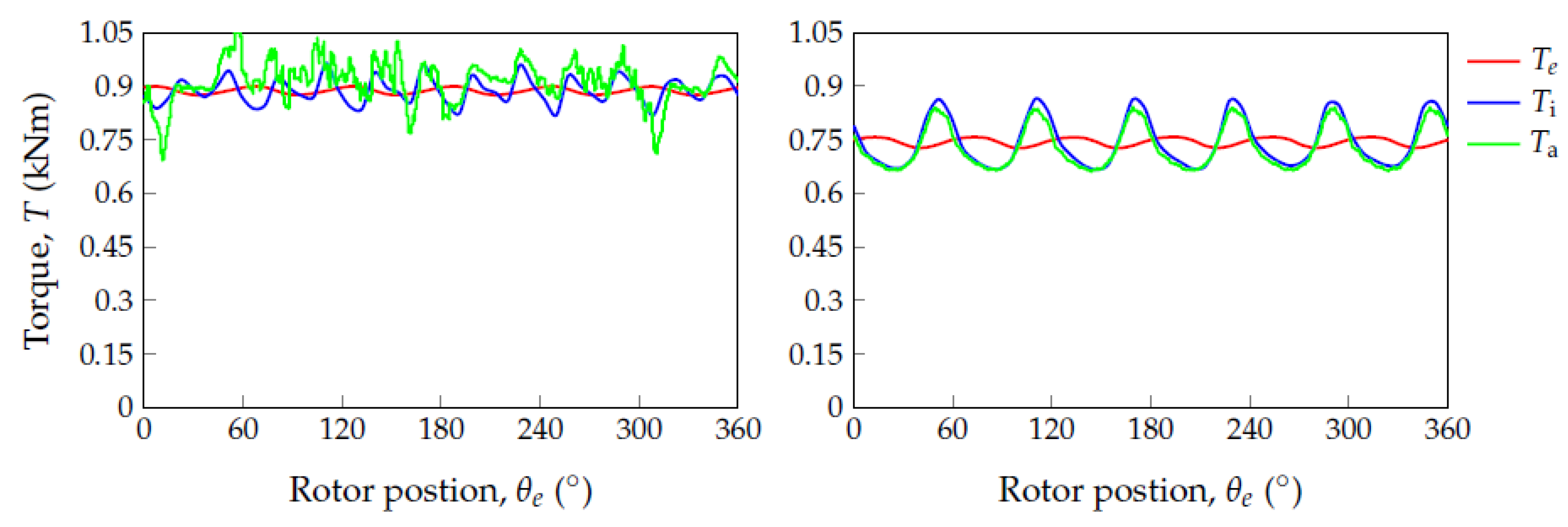
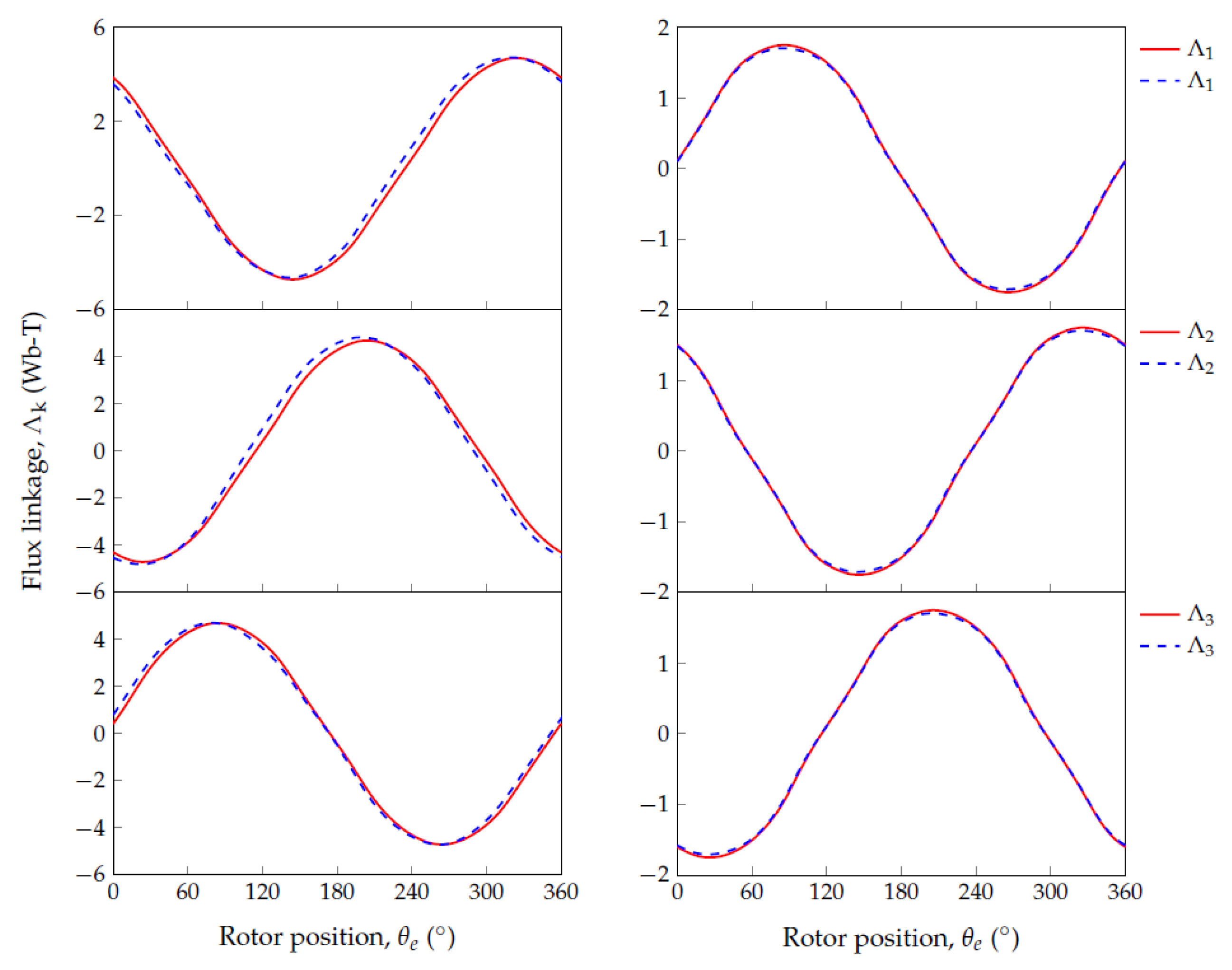
Figure 12 and
Figure 13 shows the steady-state total phase flux linkages and torque at rated current and near maximum torque current angle i.e.,
versus the electrical rotor position angle
defined in
Figure 1. The red continuous and blue dashed lines represent the flux linkages calculated from the proposed model (of (
10) using (
12)) and from Ansys–Maxwell, respectively. In
Figure 13,
,
are steady-state Maxwell stress tensor torques calculated using in-house, Ansys–Maxwell FEM software packages, respectively, and
is of (
24). The results depict a good agreement which proves the validation of the analysis presented in this paper. Note has to be taken that although Ansys–Maxwell is used for validation purposes, the transient simulation is time consuming when compared to the proposed static FEM-based analysis. The latter makes it suitable the proposed analysis in design optimization.
4. Conclusions
The use of an FEM-based non-classical modeling approach for WF-FS and DC-VR machines on a 15 kW power level has been illustrated in this paper. The approach illuminates the severe saturation effects (saturation-saliency and cross-coupling) on the model parameters of the machines at different operating points, leading to better analysis and understanding. Using electromagnetic static finite element solutions, the approach ensures accurate and computational efficient performance calculation of the two variants of WF-FMMs. In the following, the main conclusions drawn from the work in this paper are stated:
Accuracy is guaranteed on the calculation of the WF-FM machine parameters for performance, only if cross-magnetization and asymmetric saturation are considered. This is found to be critical when the q-axis current is high at maximum torque.
A less saturated WF-FSM could be more affected by cross-magnetization effect compared to the the less saturated DC-VRM, due to overlapping and less spacing between the phase- and field-winding of the former.
It is interesting that the field windings of WF-FM machines, which are aligned with the d-axes, also generates a cross-coupling q-axis field caused by relatively huge asymmetric distribution of the saturated finite element permeabilities in the machine. The q-axis field inductance is calculated to be as high as 20% and 63% of the d-axis field inductance for the WF-FSM and DC-VRM respectively. In the case of the DC-VRM, is even absolutely larger than the self inductances and under deep saturation, i.e., . This leads to a large error in the equivalent q-axis inductance, , if not taken into account.
The torques of both WF-FM machines as shown can be effectively segregated into components using the accurately calculated machine parameters. The contribution of each torque component can be used a better analyses tool in the synthesis and design optimization of both machines. It is shown, for example, that the reduced coupling or mutual torque is relatively large in both machines at maximum torque current angle. Thus, although the cross-coupling inductances are shown to be small in both machines, these inductances must not be ignored in both equivalent inductances and are essential in the torque calculation.
From the evaluated saliency () and field () ratios, it is clear that maximum torque and power factor of both WF-FM machines occur when is slightly more than and slightly below , respectively. This is clearly an indication of trade-off in their drive performance desirabilities.


