Abstract
Multi-motor systems are strong coupled multiple-input–multiple-output systems. The main objective in multi-motor drive control is to achieve synchronized operation of all motors in the system. In this paper, multi-motor systems are classified in accordance with their control demands. This paper also provides a systematic categorization of multi-motor synchronization techniques. The review of recent research literature indicates that fuzzy algorithms are widely used in multi-motor control. Finally, in this paper, a review of fuzzy logic controllers and their functionalities in multi-motor control is given.
1. Introduction
Multi-motor drives are an optimal solution for high-inertia and high-power drives, such as belt conveyors [1], as well as for long continuous lines [2]. In recent years, multi-motor drives have been increasingly implemented in electric vehicles [3] and robot manipulators [4]. Depending on drive application, control objectives are defined. Clearly, the control objectives can considerably differ depending on drive application. For example, the main objective of drive control used in continuous lines is the decoupled tracking of speed and tension. On the other hand, in electrical vehicles, the main goal of drive control is speed control with torque distribution to ensure the stability of such a vehicle. The energy efficiency improvement of the multi-motor system is also an important demand in industry and transport applications. The multi-motor system’s energy efficiency improvement possibilities are presented in [1,5].
The development of a multi-motor system control begins with choosing the relationships between motor drive units and determining the number and type of feedbacks and controllers, i.e., establishing the multi-motor control strategy. The next step is development and implementation of control algorithms which will ensure the stability and desired behavior of the system. The variety of control algorithms is developed for multi-motor system control, such as classic proportional-integral-derivative (PID) control, optimal control, control methods based on artificial intelligence, etc. In the development of new multi-motor control strategies, fuzzy logic control is widely used. It has been reported that the implementation of fuzzy logic control gives encouraging results in real-time speed error compensation [4], drive efficiency increase [1], and in rather simple and fast synchronizing rules.
The main goal of this paper is to provide a survey of multi-motor system control with emphasis on fuzzy logic control, whilst taking into consideration different control objectives of different multi-motor systems. The paper is organized as follows: Section 2 examines the categorization of multi-motor systems considering their demands and specific characteristics. Section 3 provides the classification and analysis of multi-motor synchronization strategies. In Section 4, an overview of fuzzy logic algorithms used in multi-motor control is given with the analysis of different functionalities that fuzzy controllers handle in multi-motor synchronization strategies. Finally, Section 5 presents the conclusion of the research analysis presented in the paper.
2. Multi-Motor Systems Classification
In Reference [6], multi-motor systems are divided into two major categories: systems with independent motors and systems with mechanically interconnected motors. In the literature, the term multi-motor system usually corresponds to systems with interconnected motors. Typically, each mechanical section of such a system is driven by a fully controlled drive unit, and all these drives are electronically synchronized through the master reference command [7]. A drive unit usually consists of a frequency converter and a motor, whereas the master reference command is generated in the master programmable logic controller (PLC).
Multi-motor systems are complex, often with nonlinear behavior that cannot be neglected. In addition, coordinated performance of all multi-motor system parts is affected by various external factors [8]. This yields a need for the development of fast and reliable multi-motor synchronization techniques. The proper synchronization technique depends on multi-motor system objectives and demands. Based on the objectives stated in the reviewed literature, the multi-motor systems with interconnected motors can be divided into three categories: continuous lines, robotic manipulators and electrical vehicles. The overview of objectives for these categories is presented in Table 1. These categories will be described in this section in detail.

Table 1.
Multi-motor system control objectives.
Some multi-motor systems have very specific demands and cannot be placed in the mentioned categories. Examples of such systems are the cutterhead driving system of shield machines [9] and vibration systems [10]. For the cutterhead driving system of shield machines, it is very important to achieve an equal speed and equal torque of all motors, otherwise some motors may be overloaded. Vibration systems have multiple vibration exciters for which speed and phase synchronization must be ensured.
Some complex systems incorporate multi-motor subsystems of different categories. An example of such a system is gantry cranes. The first subsystem is the hoist for raising and lowering the cargo. The second is the trolley for positioning the hoist, and the third is a gantry for driving the gantry crane through the working area. The most important feature for maintaining the stability of gantry cranes is load torque distribution. The load torque distribution techniques applicable on gantry crane systems are categorized and described in [11].
2.1. Multi-Motor Systems in Continuous Lines
Continuous lines can be modeled as nonlinear multiple-input–multiple-output (MIMO) systems with a strong mutual effect between the individual input and state quantities [2]. The mechanical interconnections between motor shafts are characterized by effects of elasticity, friction and backslash. The two-motor drive system model considering these effects is given in [8,12]. The control goals for continuous lines are summarized in [13] as follows: decoupled control of tension and speed values, invariance against additive disturbances, robustness against changes of important line parameters, dynamic responses of controlled variables without any overshoots, and stability of the controlled system. According to [14], the main objective in the regulation of such systems is to ensure that the belt or processed material’s velocity is as high as possible, while controlling its tension over the entire production line. Examples of continuous line systems are web winding systems and conveyor belts. If the control of a web winding system is not properly synchronized, then damaging, breaking and folding of material will occur [14]. In the case of conveyor belts, the lack of system synchronization may lead to spillage of the material over the belt or nonsymmetrical distribution of the material across the profile of the belt [1].
Another example of continuous lines is filling systems in the food packaging industry. According to [15], the specific problems occur in the case of filling thick sauces and sticky food because of sudden load changes at the filling motor. These abrupt load changes lead to large synchronization errors in the multi-motor system.
2.2. Multi-Motor Systems in Robotic Manipulators
Robotic manipulators are another type of multi-motor systems [4]. In this type of multi-motor systems, the main goals are to ensure the precision of tool positioning, the precise amount of force acting on a processed object, and coordinated movement according to the reference path defined by inverse kinematics in the dynamical state. As stated in [4], at present, robot manipulators are still built with weak anti-interference ability, i.e., it is still hard for robots to interact dynamically with their environment, which, in most cases, must be controlled [16]. To improve robot manipulator performance, the authors of [4] point out the importance of studying multi-motor coordinated technology. In this multi-motor system category, all other machines with synchronized multi-axis positioning tasks, such as machines for complex parts manufacturing, can be incorporated.
2.3. Multi-Motor Systems in Electrical Vehicles
In recent years, electrical vehicles have been developed with multi-motor drives. In this type of multi-motor drive, the most important objective is to maintain stability of the vehicle. To achieve stability of the vehicle, the driving torque and motor speeds must be properly distributed in every operation point (e.g., acceleration, deceleration, and vehicle turning left/right). According to [3], the two-side motor-independent drive is the most widely used transmission scheme, and the synchronization and coordination control problem is a key problem in the research and development of this kind of vehicle. The authors of [17] point out another feature necessary for the reliability of electrical vehicles: the electrical vehicle must be a fault-tolerant system, i.e., in the case of one drive unit failure, the stability of the system must be maintained with the rest of the drive units. This being the case, the authors propose a fault-tolerant controller based on sliding mode techniques. Further bibliographic review and study of fault-tolerant diagnosis and control systems for multi-motor electric vehicles can be found in [18]. The implementation of the electrical vehicle drive control algorithm with torque distribution on an FPGA platform is described in [19]. In Reference [20], a new type of braking power distribution for distribution-driven electrical vehicles is introduced. The road state and condition estimation as well as the relationship between the tire and road surface are described and considered in slip controller design.
3. Multi-Motor Synchronization Techniques
A successful synchronization technique of the multi-motor system must include the control of two motor mechanical variables: the speed and the torque [21]. The methods used in single-input–single-output systems may provide stability in stationary operating points; however, as pointed out in [2], they cannot ensure the desired autonomy of control of individual output quantities in dynamical states. An additional issue that often arises in multi-motor system control is significant lagging of control and disturbance signals.
The categorization of multi-motor control strategies can be divided into two main categories, the classical control strategy and modern control strategy. In the following subsections, each category will be discussed in detail.
3.1. Classical Multi-Motor Control Strategies
The classical multi-motor control strategies are based on PI (proportional-integral) or PID controllers and can be divided into [3] parallel control, master–slave control and cross-coupling mode.
In the parallel control strategy (Figure 1a), there is one reference signal which is brought parallel to all drive units. This control strategy is simple, but in the case of disturbances, the synchronous operation of drive units will be lost, since there is no feedback signal from the single unit to the master control of the system.
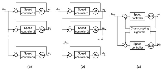
Figure 1.
Classical multi-motor control strategies: (a) parallel control, (b) master–slave control, (c) cross-coupling control.
In the master–slave control strategy (Figure 1b), the speed of one drive is the reference signal for the next drive unit. In this way, the speed of the slave motor always tracks the change in speed of the previous motor, but in the case of disturbances occurring at the slave unit, the synchronism will not be preserved as there is no feedback from the slave units, and all prior motors will not track such a change in speed. The speed of all motors after such disturbance becomes equal after a certain delay, but synchronization in the meaning of position cannot be restored.
The cross-coupling strategy (Figure 1c) establishes the coupling relation between all motor units in the system. In this way, the control and tracking precision is high, and synchronization of motors will be preserved in the case of disturbances. However, the complexity of this strategy significantly increases with the number of controlled drive units and, as stated in [4], may become unstable for occasions with high synchronization precision requirements.
3.2. Modern Multi-Motor Control Strategies
The literature overview shows significant development of new multi-motor control strategies in recent years. The modern multi-motor control strategies can roughly be divided into the ring coupling control strategy, the relative coupling strategy, the adjacent tracking strategy and coordinated control. Various combinations of these strategies are also being developed, e.g., combined cross-coupling error control.
3.2.1. Ring Coupling Control
The ring coupling control strategy (Figure 2a) combines the principles of classical multi-motor control strategies to ensure the synchronization in the case of disturbances occurring at any place in the system whilst keeping the control structure rather simple. As in the parallel control strategy, there is only one speed reference signal. Additionally, the speed of each motor is compared to the speed of the following motor and brought to the compensator, which generates the additional input signal in the speed controller of a drive unit. The speed of the last motor is compared to the speed of the first motor in the system, which ensures the synchronization of all motors regardless of the place that disturbance appears. This finally leads to the conclusion that for the n-motor system, there will be 2n controllers in the ring coupling control strategy [22].
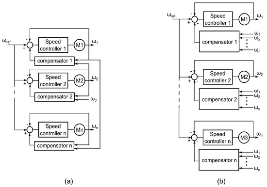
Figure 2.
Modern multi-motor control strategies: (a) ring coupling control and (b) relative coupling control.
3.2.2. Relative Coupling Control
The relative coupling control strategy (Figure 2b) solves the problem of successful system synchronization for disturbance occurring at any drive unit by considering all speed feedbacks for acquiring an additional control signal for every drive unit. The advantage of this method is that all motor speed feedbacks are equally important, and the algorithm used to obtain the additional control signals is rather simple. For the i-th drive unit, the additional signal is calculated as follows [23]:
where is the coupling coefficient and denotes the inertia of the i-th motor. represents the angular velocity of the i-th motor. In Reference [23], an improved relative coupling control structure is proposed. In this structure, the importance of speed of each motor is taken into consideration through an importance factor. Setting the importance factor for each motor speed provides the possibility to define a weighted average value of all motor speeds in the system called the system speed. In this way, the whole system contains only one feedback process, the system speed. This being the case, the complexity of the system is reduced. Another advantage of the proposed method is that tracking and synchronization performances are decoupled to some extent by adjusting synchronization and tracking coefficients independently.
3.2.3. Adjacent Coupling Control
In the adjacent coupling strategy (Figure 3a), a speed tracking controller and a speed synchronization controller are also needed for every motor. The speed tracking controller generates the control signal for tracking the speed reference value, and the speed synchronization controller is used to synchronize the speed among the controlled motor and its two adjacent motors [24]. The outputs of these controllers are summarized in one torque command of the motor. The speed and synchronization controller can be constructed in accordance with various control methods. In References [24,25], speed and tracking controllers are based on the sliding mode control method. In Reference [25], the enhanced adjacent coupling strategy is proposed. The authors introduce coupling coefficients into the adjacent coupling approach to simplify the controller structure. The stability of the controlled system is more easily proved in this case than in the case of the classical adjacent coupling strategy.
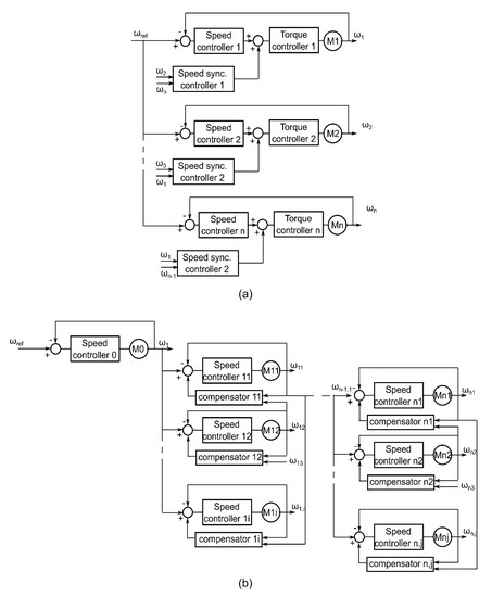
Figure 3.
Modern multi-motor control strategies: (a) adjacent coupling control and (b) combined cross-coupling error control.
3.2.4. Combine Cross-Coupling Error Control
A novel control strategy for complex multi-motor systems containing a larger number of drive units is proposed in [26]. The proposed strategy divides the complex multi-motor system into subsystems, as shown in Figure 3b. There is one main master drive unit in the system, which is the reference for synchronization of subsystems in accordance with the master–slave control strategy. In each subsystem, one drive unit is the master unit, and for drive synchronization in the subsystem, the ring coupling strategy is used. The authors in [26] refer to subsystem drive synchronization as synchronization between layers. The synchronization of subsystems is denoted as synchronization between axes.
3.2.5. Coordinated Coupling Control
In the coordinated control strategy (Figure 4), besides the main reference speed and speed controllers in each drive unit, as in the case of the classical parallel control strategy, the coordinated controller is introduced. As explained in [8], the coordinated controller is presented to quickly compensate the motor speed with the highest relative error while preserving the stability of other motors. This controller must act fast and is by nature experience based. This is why the coordinated controllers are based on artificial intelligence techniques, such as neural networks and fuzzy algorithms. An example of an adaptive mutation particle swarm optimization PID neural network learning algorithm of motor synchronization control can be found in [27]. As explained in [3], the most suitable technique for coordinated controller design recognized by researches to date is fuzzy logic control. Examples of the coordinated control strategy based on fuzzy algorithms are discussed in the next section.
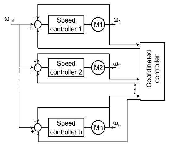
Figure 4.
Modern multi-motor control strategies: coordinated coupling control.
3.3. Comparison of Multi-Motor Control Strategies
Each control strategy presented in the previous subsections has its advantages and drawbacks. The most appropriate control strategy should be chosen for the multi-motor system depending on specific demands of the system and control strategy features. A detailed comparison of the synchronization strategies is given in Table 2.
Table 2.
Comparison of multi-motor synchronization strategies.
For example, for continuous lines, it is often more important that the specific motor follows the speed of the previous motor in the system than achieving the main reference speed. This being the case, master–slave control could be a good option for continuous lines without the need for position synchronization. If the continuous line is a very complex system with the need for synchronized positioning of some subsystems, a combine cross-coupling error control could be the appropriate choice. On the other hand, these two methods are not the appropriate choice for robotic manipulators. For robotic manipulators, coordinated control is often used because of its simple control structure and minimal lagging of the control signal.
4. Fuzzy Algorithms in Multi-Motor System Control
As discussed in Section 2, multi-motor systems are strongly coupled nonlinear MIMO systems. These systems are complex and hard to model considering all nonlinearities and mechanical coupling effects. In addition, many uncertainties caused by external conditions (wind gusts and unpredictable road conditions for electrical vehicles, material thickness and spacing on the conveyor belts for continuous lines, etc.) can affect the operating conditions of individual motors in the system. This being the case, fuzzy algorithms are convenient for implementation in multi-motor system control because of the following two advantages: the fuzzy algorithm is based on defining states similar to narrative expression of experience, and the needed knowledge of controlled technology is minimal. This means that nonlinear input/output relationships can be expressed by a set of qualitative “if–then” rules [2]. Further on, as pointed out in [4], fuzzy control can be used to distinguish different types of disturbances to different fuzzy areas during operation and, thus, improve the coordination of the multi-motor operation. Two different fuzzy inference systems exist, namely, the Mamdani and the Takagi–Sugeno inference systems. The Takagi–Sugeno fuzzy rule base uses linear functions of inputs to predict the output, whereas the Mamdani inference system determines outputs through fuzzy sub-sets [28]. A detailed review of Mamdani inference systems is given in [29], and in [30] Takagi–Sugeno fuzzy modeling is described.
In research papers dealing with multi-motor control, there are several different functionalities of fuzzy logic control reported. The fuzzy algorithms are used for modelling nonlinear coupling effects between individual drives in the system; for speed control of individual motors; and as compensators used in the ring coupling control strategy, the relative coupling strategy, the adjacent tracking strategy or coordinators if the coordinated control strategy is used. The fuzzy-based model of nonlinear coupling effects between individual drives in the continuous line system is developed in [2].
The theoretical background of fuzzy PID controllers can be found in [31]. Fuzzy controllers used as compensators or for speed regulation usually have two inputs, error e and error change ec = de/dt and one [4,8] or two outputs [25,32]. The authors mostly use three [12,32], five [25,33,34] or seven [4,35] membership functions for inputs. The number of membership functions defined for output variables in most cases is the same as the number of membership functions for input variables, but may be smaller [1] or larger [8,36] depending on application. For example, in [8], there are seven membership functions for each input and thirteen membership functions for the output variable. For fuzzy logic controllers used in multi-motor system control, to calculate the output scale value, the most often used methods are the center of gravity and the weighted average. As stated in [28], the center of gravity method is used with the Mamdani model and weighted average in the Takagi–Sugeno model. The center of gravity defuzzification method for continuous functions is given with the following equation [4]:
where denotes the output fuzzy set corresponding to the z-th error fuzzy set , the j-th fuzzy set of error change , denotes the membership function of the output, and is the control output value. For discrete functions, the center of gravity method is given with Equation (3) [37]:
where represents the sub-area of the total area A of output membership function distribution, represents the centroid of the sub-area, and n represents the number of the sub-area of A. The weighted average is defined as [35]:
In Equation (4), denotes the membership function, represents the middle element of the i-th fuzzy set, and n represents the number of output membership functions. It is important to note that the weighted average method can be used only with symmetrical membership functions.
When designing a fuzzy controller, authors often encounter the problem of a large overshoot in the case of larger input value changes. This problem can be solved by introducing a larger number of membership functions for a more detailed description of the desired behavior of the controller. An example of this phenomenon is motor start-up. In this case, the control error is big and positive, and the control error change is also big and positive, thus, the control output should be big and positive. As the motor speed increases, the control error decreases. If the output remains the same, a large speed overshoot will occur. This means that the control output should now be small and positive, or even negative, depending on the control error change rate. However, it should be noted that the larger number of membership functions describing behavior of input and output variables implies a larger number of fuzzy rules (typically, if the number of membership functions for each variable is n, the number of rules equals n2) and a slower control algorithm. Another problem is the time-consuming tuning of the fuzzy controller. These two problems can be solved using artificial intelligence algorithms, such as neural networks [2], immune control [36], particle swarm optimization or simulated annealing [32] for tuning the fuzzy controller.
4.1. Fuzzy Speed Controllers for Individual Motors of Multi-Motor System
The fuzzy PID algorithm for control of the slave motor speed in the two-motor system is reported in [38]. The chosen synchronization strategy for the two-motor system is master–slave. A similar adaptive fuzzy PID controller is developed in [8] for the three-motor system. According to the authors, such a controller enables fast tracking and disturbance elimination. In Reference [39], a genetic algorithm is used to adjust the rules and membership functions of speed fuzzy PID controllers implemented in the digital signal processor (DSP) for control of a multi-fingered robot manipulator.
In Reference [35], the authors propose variable universe fuzzy PI speed controllers for permanent magnet synchronous motors of a multi-motor system. The main goal of introducing the variable universe interpolation is to enable a change in fuzzy rules without increasing the rule number. In this way, if the controlled object (a motor with an operating mechanism) changes, the control quality of the existing controller can be easily improved.
In References [25,40,41], fuzzy logic rules are used to adjust the coefficients of the extended state observer (ESO) to improve the speed control of each drive. The ESO is introduced in control schemes to observe multi-motor system states and lumped disturbances, including nonlinearities and uncertainties. In this way, fuzzy active disturbance rejection control is achieved, which enables disturbance estimation and compensation of a multi-motor system.
Nonlinear fuzzy immune control is implemented in [36]. The presented experimental results show that the multi-motor control strategy with such speed controllers enables decoupling of speed and tension tracking.
4.2. Fuzzy Speed Controllers
In Reference [8], the authors developed a fuzzy coordinator of a multi-motor system. The coordinated controller is tuned to quickly compensate the speed error of a motor with the largest relative error while preserving the stability of the whole system.
In Reference [12], the authors introduced a fuzzy technique proposed by Takagi–Sugeno–Kang to eliminate the chattering phenomenon which occurs in the two-motor drive system with an adaptive sliding mode controller used to obtain tracking effectiveness. The fuzzy algorithm is used to adjust the coefficient of the sliding mode controller.
The authors in [34] introduce robust fuzzy PID controllers of the three-motor system using Simulated Annealing Optimization (SAO). The SAO algorithm is introduced to reduce strong coupling influences between drive units. The proposed method is tested in MATLAB/Simulink simulation of a three-motor system of a belt–pulley. The theoretical background of fuzzy algorithm systems with reduced parametric sensitivity based on simulated annealing optimization can be found in [32].
4.3. Fuzzy Compensators Used in Multi-Motor Systems
In Reference [1], the authors reported practical implementation of fuzzy logic control based on Mamdani’s reasoning methods to achieve the variable acceleration and deceleration of an excavator–conveyor–spreader system on an open-pit mine. Fuzzy logic control was introduced to calculate the acceleration and deceleration rate for a single belt conveyor motor of a drive based on the speed of the previous belt conveyor motor, cross-section of incoming material and the drive torque. The master PLC generates the reference speed which is the input for a classical PI controller that generates the torque reference for the direct torque control. The fuzzy algorithm used in [1] is explained in detail in [33]. In the paper, the relative coupling synchronization strategy is used. The energy efficiency improvement with the newly proposed fuzzy logic controller is experimentally proved. In Reference [42], a combination of particle swarm optimization and fuzzy control was applied in coordinated control of an automated guided vehicle. It is concluded that the proposed control ensures stable operation of such a vehicle with a faster response to disturbances.
The authors in [4] introduced fuzzy compensators in the cross-coupled ring strategy. The fuzzy algorithm is implemented to change the control parameters of the motor speed controllers in real time based on the speed errors of two adjacent motors. The proposed control quality is tested in semi-physical simulation of a four-motor system with the MATLAB/Simulink and the RT-LAB real-time simulation platform. The results show that fuzzy control improves the tracking performance of a multi-motor system.
5. Discussion
In recent years, the multi-motor systems have been increasingly developed and implemented for industry applications and electrical vehicles. The first step to ensure fast and precise operation of a system prone to disturbances as well as the stability of such a system is to state all of its control demands and objectives. Then, an appropriate synchronization strategy and control methods can be chosen.
The literature overview shows that for high-demand multi-motor systems, modern synchronization strategies are the appropriate choice. These synchronization strategies ensure synchronization in the case of disturbances occurring at any place in the system and enable decoupled control of important system values, such as speed and tension. However, they are still rather complex and demand a large number of feedbacks. Typically, to implement such a synchronization strategy for coordinated operation of a n-motor system, 2n controllers are needed.
Furthermore, the literature overview shows that the presented multi-motor control strategies are suitable for use in practical multi-motor systems, as many research papers report successful experimental implementation of the proposed control algorithms. The experimental setups can be found in [2,23,39]. Successful implementation of the coordinated control strategy based on fuzzy ring network control is proven with real-time simulation in [4]. In Reference [1], the proposed multi-motor control strategy is implemented to control a real excavator–conveyor–spreader system. Due to its nonlinear behavior and the complexity of the system, the control rules are difficult to obtain analytically. Besides, to achieve fast dynamics in reference tracking and disturbance compensation, additional control delay should be avoided. This leads to the conclusion that the control algorithms used in multi-motor system control should be as simple as possible. The control method that fulfills all stated demands is fuzzy logic control. The literature overview presented in this paper shows that the fuzzy logic control algorithms for multi-motor control and synchronization are being increasingly developed. Moreover, successful implementation of fuzzy logic algorithms as speed controllers, compensators and coordinators for multi-motor systems is reported.
Fuzzy logic control has drawbacks that still need to be solved. Setting up a rule base with more than three inputs while preserving end-user interpretability is nearly impossible [43]. Additionally, the performance of fuzzy controllers in boundary states can lead to problems with control dynamics and stability [2].
It can be concluded that further research objectives should be the reduction of the number of controllers and feedbacks needed for multi-motor system control and development of flexible control algorithms based on artificial intelligence. The coordinated control strategy based on artificial intelligence control algorithms gives the most promising results because of the simple control structure, but there is still the need for further improvement of control algorithms.
Author Contributions
Conceptualization, V.J.Š.; methodology V.J.Š. and T.V.; validation T.V. and T.B.; formal analysis, V.J.Š. and M.B.; investigation V.J.Š.; resources: V.J.Š. and T.V.; data curation: V.J.Š. and M.B.; writing—original draft preparation, V.J.Š.; writing—review and editing, T.V., T.B. and M.B.; visualization, V.J.Š., supervision: M.B.; project administration, M.B.; funding acquisition, M.B. All authors have read and agreed to the published version of the manuscript.
Funding
This work has been supported in part by the Croatian Science Foundation under the project number UIP-05-2017-8572.
Conflicts of Interest
The authors declare no conflict of interest.
References
- Ristić, L.; Bebić, M.; Jetvić, D.; Jeftenić, B.; Štatkić, S.; Nikolić, A. Controlled multi motor drives of high power belt conveyors: Practical experiences during the exploitation of the system on open pit mine. In Proceedings of the 13th WSEAS International Conference on Electric Power Systems, High Voltages, Electric Machines (POWER 13), Chania, Greece, 27–29 August 2013; pp. 65–70. [Google Scholar]
- Perdukova, D.; Fedor, P.; Bacik, J.; Herčko, J.; Rofar, J. Multi-motor drive optimal control using a fuzzy model based approach. J. Ambient. Intell. Smart Environ. 2017, 9, 329–344. [Google Scholar] [CrossRef]
- Huang, H.; Tu, Q.; Jiang, C.; Ma, L.; Li, P.; Zhang, H. Dual motor drive vehicle speed synchronization and coordination control strategy. In ADVANCES IN MATERIALS, MACHINERY, ELECTRONICS II: Proceedings of the 2nd International Conference on Advances in Materials, Machinery, Electronics (AMME 2018); AIP Publishing: College Park, MD, USA, 2018; Volume 1955, p. 040005. [Google Scholar] [CrossRef]
- Wu, Y.; Cheng, Y.; Wang, Y. Research on a Multi-Motor Coordinated Control Strategy Based on Fuzzy Ring Network Control. IEEE Access 2020, 8, 39375–39388. [Google Scholar] [CrossRef]
- Ganiev, R. Reversible frequency converters in the composition of multimotor electric drives. IOP Conf. Series: Mater. Sci. Eng. 2019, 643, 012068. [Google Scholar] [CrossRef]
- Yanbo, C.; Lin, S.; Cheng, K.W.E. Variable Gain Intelligent Control of Multi-motor Synchronization System. In Proceedings of the 2006 2nd International Conference on Power Electronics Systems and Applications, Hong Kong, China, 12–14 November 2006; pp. 68–72. [Google Scholar] [CrossRef]
- Valenzuela, M.A.; Lorenz, R.D. Electronic line-shafting control for paper machine drives. In Proceedings of the Conference Record of 2000 Annual Pulp and Paper Industry Technical Conference, Atlanta, GA, USA, 19–23 June 2000; pp. 106–112. [Google Scholar] [CrossRef]
- Gao, D.C.; He, F. Fuzzy Coordinated Control for Multi-Motor Drive System. Appl. Mech. Mater. 2014, 631, 676–679. [Google Scholar] [CrossRef]
- Liu, R.; Sun, J.Z.; Luo, Y.Q.; Sun, W.; Li, W.D. Research on Multi-Motor Synchronization Control Based on the Ring Coupling Strategy for Cutterhead Driving System of Shield Machines. Appl. Mech. Mater. 2011, 52–54, 65–72. [Google Scholar] [CrossRef]
- Huang, Z.; Li, Y.; Song, G.; Zhang, X.; Zhang, Z. Speed and Phase Adjacent Cross-Coupling Synchronous Control of Multi-Exciters in Vibration System Considering Material Influence. IEEE Access 2019, 7, 63204–63216. [Google Scholar] [CrossRef]
- Mitrovic, N.; Kostić, V.; Petronijevic, M.; Jeftenic, B. Multi-Motor Drives for Crane Application. Adv. Electr. Comput. Eng. 2009, 9, 57–62. [Google Scholar] [CrossRef]
- Tinh, T.X.; Thanh, P.T.; Van Tuyen, T.; Van Tien, N.; Dao, P.N. A fuzzy adaptive sliding mode controller for uncertain nonlinear multi motor systems. In MATEC Web of Conferences; EDP Sciences: Ulis, France, 2018; Volume 161, p. 02013. [Google Scholar]
- Perdukova, D.; Fedor, P.; Fedák, V.; Padmanaban, S. Lyapunov Based Reference Model of Tension Control in a Continuous Strip Processing Line with Multi-Motor Drive. Electronics 2019, 8, 60. [Google Scholar] [CrossRef]
- Abjadi, N.; Askari, J.; Soltani, J.; Markadeh, G.A. Nonlinear sliding-mode control of a multi-motor web-winding system without tension sensor. IET Control. Theory Appl. 2009, 3, 419–427. [Google Scholar] [CrossRef]
- Zhang, C.; Xiao, M.; He, J. Multimotor Improved Relative Coupling Cooperative Control Based on Sliding-Mode Controller. Math. Probl. Eng. 2020, 2020, 1–10. [Google Scholar] [CrossRef]
- Jimenez-Fernandez, A.; Jimenez-Moreno, G.; Linares-Barranco, A.; Dominguez-Morales, M.J.; Vicente, R.P.; Civit-Balcells, A. A Neuro-Inspired Spike-Based PID Motor Controller for Multi-Motor Robots with Low Cost FPGAs. Sensors 2012, 12, 3831–3856. [Google Scholar] [CrossRef] [PubMed]
- Almeida, S.; Araujo, R.E. Fault-tolerant control using sliding mode techniques applied to multi-motor electric vehicle. In Proceedings of the IECON 2013-39th Annual Conference of the IEEE Industrial Electronics Society, Vienna, Austria, 10–13 November 2013; pp. 3530–3535. [Google Scholar] [CrossRef]
- Silveira, A.M.; Araujo, R.E.; De Castro, R. Survey on Fault-Tolerant Diagnosis and Control Systems Applied to Multi-motor Electric Vehicles. In IFIP Advances in Information and Communication Technology; Springer: Berlin, Germany, 2011; Volume 349, pp. 359–366. [Google Scholar] [CrossRef]
- De Castro, R.; Araujo, R.E.; Oliveira, H. Control in Multi-Motor Electric Vehicle with a FPGA platform. In Proceedings of the 2009 IEEE International Symposium on Industrial Embedded Systems, Lausanne, Switzerland, 8–10 July 2009; pp. 219–227. [Google Scholar] [CrossRef]
- Yu, D.; Wang, W.; Zhang, H.; Xu, D. Research on Anti-lock Braking Control Strategy of Distributed-Driven Electric Vehicle. IEEE Access 2020, 8, 1. [Google Scholar] [CrossRef]
- He, F.; Tong, W.; Wang, Q. Synchronization Control Strategy of Multi-motor System Based on Profibus Network. In Proceedings of the 2007 IEEE International Conference on Automation and Logistics, Jinan, China, 18–21 August 2007; pp. 3029–3034. [Google Scholar]
- Li, L.-B.; Sun, L.-L.; Zhang, S.-Z.; Yang, Q.-Q. Speed tracking and synchronization of multiple motors using ring coupling control and adaptive sliding mode control. ISA Trans. 2015, 58, 635–649. [Google Scholar] [CrossRef] [PubMed]
- Shi, T.; Liu, H.; Geng, Q.; Xia, C. Improved relative coupling control structure for multi-motor speed synchronous driving system. IET Electr. Power Appl. 2016, 10, 451–457. [Google Scholar] [CrossRef]
- Zhao, D.; Li, C.; Ren, J. Speed synchronization of multiple induction motors with adjacent cross coupling control. In Proceedings of the Proceedings of the 48th IEEE Conference on Decision and Control (CDC) held jointly with 2009 28th Chinese Control Conference, Shanghai, China, 15–18 December 2009; pp. 6805–6810. [Google Scholar]
- Tao, L.; Chen, Q.; Nan, Y.; Dong, F.; Jin, Y. Speed Tracking and Synchronization of a Multimotor System Based on Fuzzy ADRC and Enhanced Adjacent Coupling Scheme. Complexity 2018, 2018, 1–16. [Google Scholar] [CrossRef]
- Xu, J.; Lu, H.; Liu, X. Synchronization control strategy in multi-layer and multi-axis systems based on the combine cross coupling error. Adv. Mech. Eng. 2017, 9, 1–11. [Google Scholar] [CrossRef]
- Gao, Z.; Sun, J. Application of Improved PSO and PID Neural Network Controller for Multi-motor Proportion Synchronous Control System. DEStech Trans. Comput. Sci. Eng. 2017, 2016, 217–225. [Google Scholar] [CrossRef][Green Version]
- Özger, M. Comparison of fuzzy inference systems for streamflow prediction. Hydrol. Sci. J. 2009, 54, 261–273. [Google Scholar] [CrossRef]
- Cordón, O. A historical review of evolutionary learning methods for Mamdani-type fuzzy rule-based systems: Designing interpretable genetic fuzzy systems. Int. J. Approx. Reason. 2011, 52, 894–913. [Google Scholar] [CrossRef]
- Hadjili, M.L.; Kara, K. Modelling and control using Takagi-Sugeno fuzzy models. In Proceedings of the 2011 Saudi International Electronics, Communications and Photonics Conference (SIECPC), Riyadh, Saudi Arabia, 24–26 April 2011; pp. 1–6. [Google Scholar] [CrossRef]
- Xu, J.-X.; Hang, C.-C.; Liu, C. Parallel structure and tuning of a fuzzy PID controller. Automatica 2000, 36, 673–684. [Google Scholar] [CrossRef]
- Precup, R.-E.; David, R.-C.; Petriu, E.M.; Preitl, S.; Rădac, M.-B. Fuzzy Control Systems With Reduced Parametric Sensitivity Based on Simulated Annealing. IEEE Trans. Ind. Electron. 2011, 59, 3049–3061. [Google Scholar] [CrossRef]
- Ristic, L.B.; Jeftenic, B.I. Implementation of Fuzzy Control to Improve Energy Efficiency of Variable Speed Bulk Material Transportation. IEEE Trans. Ind. Electron. 2011, 59, 2959–2969. [Google Scholar] [CrossRef]
- Salem, F.; Bayoumi, E.H.E. Robust Fuzzy-PID Control of Three-Motor Drive System Using Simulated Annealing Optimization. IEEE Trans. Ind. Electron. 2013, 3, 284–292. [Google Scholar]
- Tian, Z.; Li, S.; Wang, Y.; Zang, Q. Multi Permanent Magnet Synchronous Motor Synchronization Control based on Variable Universe Fuzzy PI Method. Eng. Lett. 2015, 23, 1–9. [Google Scholar]
- Hui, L.; Xingqiao, L.; Jing, L. The research of Fuzzy Immune Linear Active Disturbance Rejection Control Strategy for three-motor synchronous system. Control. Eng. Appl. Inform. 2015, 17, 50–58. [Google Scholar]
- Samanta, D. Defuzzification Methods, Chapter 5, course Soft Computing Applications. Available online: https://cse.iitkgp.ac.in/~dsamanta/courses/archive/sca/Archives/Chapter%205%20Defuzzification%20Methods.pdf (accessed on 18 May 2020).
- Li, M.; Meng, X. Analysis and Design of System for Multi-motor Synchronous Control. In Proceedings of the Neural Networks for Modelling and Control of Dynamic Systems, Wuhan, China, 21–22 August 2011; pp. 268–273. [Google Scholar]
- Ataei, E.; Afshari, R.; Pourmina, M.A. Fuzzy Logic Control of a Multifingered Hand Robot Using Genetic Algorithm Based on DSP. Int. Rev. Autom. Control. 2011, 4, 1–6. [Google Scholar]
- Tang, L.; Liu, X.; Zhu, L. Study on Three-motor Synchronous System of Fuzzy Active Disturbance Rejection Control. Appl. Mech. Mater. 2012, 224, 543–546. [Google Scholar] [CrossRef]
- Shen, C.; Yang, H. A New Three-Motor Drive System Using Fuzzy Active Disturbance Rejection Control. Autom. Control. Comput. Sci. 2020, 54, 207–215. [Google Scholar] [CrossRef]
- Hu, Y.; Sun, Z.; Zhou, H. Research on Improved Deviation Coupling AGV Multi-motor Coordinated Drive Control Based on PSO-Fuzzy. In Proceedings of the 2019 4th International Conference on Automatic Control and Mechatronic Engineering, Chongqing, China, 30–31 May 2019; pp. 185–189. [Google Scholar] [CrossRef]
- Albertos, P.; Sala, A.; Olivares, M. Fuzzy Logic Controllers. Methodology, Advantages and Drawbacks. In Proceedings of the X Congreso Español sobre Tecnologías y Lógica Fuzzy, Sevilla, Spain, 20–22 September 2000; pp. 1–11. [Google Scholar] [CrossRef]


Publisher’s Note: MDPI stays neutral with regard to jurisdictional claims in published maps and institutional affiliations. |
© 2020 by the authors. Licensee MDPI, Basel, Switzerland. This article is an open access article distributed under the terms and conditions of the Creative Commons Attribution (CC BY) license (http://creativecommons.org/licenses/by/4.0/).