Article

Optimal Transient Search Algorithm-Based PI Controllers for Enhancing Low Voltage Ride-Through Ability of Grid-Linked PMSG-Based Wind Turbine

by
Mohammed H. Qais
1,*,
Hany M. Hasanien
2 and
Saad Alghuwainem
1
1
Electrical Engineering Department, College of Engineering, King Saud University, Riyadh 11421, Saudi Arabia
2
Electrical Engineering Department, Faculty of Engineering and Technology, Future University in Egypt, Cairo 11835, Egypt
*
Author to whom correspondence should be addressed.
Electronics 2020, 9(11), 1807; https://doi.org/10.3390/electronics9111807
Submission received: 6 October 2020 / Revised: 20 October 2020 / Accepted: 29 October 2020 / Published: 31 October 2020
(This article belongs to the Section Industrial Electronics)

Abstract

:
This paper depicts a new attempt to apply a novel transient search optimization (TSO) algorithm to optimally design the proportional-integral (PI) controllers. Optimal PI controllers are utilized in all converters of a grid-linked permanent magnet synchronous generator (PMSG) powered by a variable-speed wind turbine. The converters of such wind energy systems contain a generator-side converter (GSC) and a grid-side inverter (GSI). Both of these converters are optimally controlled by the proposed TSO-based PI controllers using a vector control scheme. The GSC is responsible for regulating the maximum power point, the reactive generator power, and the generator currents. In addition, the GSI is essentially controlled to control the point of common coupling (PCC) voltage, DC link voltage, and the grid currents. The TSO is applied to minimize the fitness function, which has the sum of these variables’ squared error. The optimization problem’s constraints include the range of the proportional and integral gains of the PI controllers. All the simulation studies, including the TSO code, are implemented using PSCAD software. This represents a salient and new contribution of this study, where the TSO is coded using Fortran language within PSCAD software. The TSO-PI control scheme’s effectiveness is compared with that achieved by using a recent grey wolf optimization (GWO) algorithm–PI control scheme. The validity of the proposed TSO–PI controllers is tested under several network disturbances, such as subjecting the system to balanced and unbalanced faults. With the optimal TSO–PI controller, the low voltage ride-through ability of the grid-linked PMSG can be further improved.

1. Introduction

The remarkable development of wind power has become a pressing modern energy subject all over the world. This is due to the need to obtain new electrical power sources, avoid the need for fossil fuels, and the target to obtain clean energy, considering the environmental concerns [1]. Wind power represents the second-largest source after hydropower sources worldwide [2]. The wind power industry is extensively developed, resulting in a bright future of renewable energy sources. Based on the Global Wind Energy Council’s statistical analysis and annual report, the last year (2019) was an outstanding year for the wind power industry, where 60.4 GW was globally installed by the end of 2019 [3]. The total cumulative wind power capacity reached 651 GW. An increase in wind power installation by 17% was achieved compared with that obtained in 2018. It is expected that this type of renewable energy source shall increase in the future and will rigorously contribute to the electricity market [4]. It can be noted from this numerical analysis that a high level of wind power is penetrated in electric power networks [5]. Therefore, several problems have arisen, and these issues should be studied, investigated, and solved to obtain an efficient operation of wind energy conversion systems [6]. In fact, most of these problems come from the sophisticated and intermittent nature of wind power, which is based on the cube of wind speed [7]. One of the main problems that this wind power system faces is enhancing the low voltage ride through (LVRT) of the grid-connected wind energy systems [8]. Power grids have recently imposed grid codes on wind power systems to remain connected and support the power grid during grid faults [9]. This generally enhances the power grids’ stability and reliability. Therefore, wind power plants should satisfy the LVRT requirements [10]. This study focuses on strengthening the LVRT of grid-linked variable-speed wind turbine (VSWT) that drives a permanent magnet synchronous generator (PMSG).
The variable-speed wind turbines are the most commonly used in the wind power industry. These turbines have higher capture power, better control of maximum power point, higher efficiency, and lower mechanical stress than fixed-speed wind turbines [11]. Several generators have been implemented in this technology like doubly-fed induction generator (DFIG) [12], PMSG [13,14,15], and switched reluctance generator [16]. PMSGs possess many magnetic poles with large air gaps. Hence, the PMSG can rotate at lower speed compacting with the wind turbine without needing a gearbox. This technology reduces system costs and losses [17].
The VSWT–PMSG system is directly coupled with the main grid via a generator-side converter (GSC), a DC link capacitor, and a grid-side inverter (GSI) [18]. In general, the cascaded control scheme is utilized in controlling both converters. The cascaded control system controls the generator’s real and reactive power and the generator currents through the GSC. Moreover, the vector control can control the point of common coupling (PCC) voltage, the DC link voltage, and the grid currents through the GSI. Several control strategies have been used to control VSWT–PMSG systems. In [19], a linear quadratic regulator controller is introduced to obtain high performance of the VSWT–PMSG. However, many mathematical calculations are needed to simplify the quadratic regulator. In addition, the fuzzy logic controllers are presented to achieve better performance of such systems by using the Sugeno fuzzy system [20]. Although the fuzzy logic controllers can efficiently deal with the system nonlinearity and do not need the system’s mathematical model, they depend mainly on the designer experience. Additionally, optimal fuzzy logic controllers are very complex, where they involve many design variables to be fine-tuned. In [21], an adaptive neuro-fuzzy inference system is proposed to improve the system performance with the cooperation with genetic algorithms. However, this type of controllers is very complex and has several mathematical procedures. In the wind power industry, the proportional-integral (PI) controller is still the most capable of doing the control task, where it possesses a large stability margin. However, the PI controller suffers from its high sensitivity to the system parameters variation nonlinearity of the system under study. In these heavy nonlinear systems, like the wind energy conversion system, it is not easy to represent the system by transfer functions or state-space models mathematically. Therefore, many optimization methods and algorithms have been applied to design the PI controllers in such systems, such as genetic algorithm [22], the Taguchi method [23], water cycle algorithm [24], grey wolf optimizer [25], enhanced whale optimization algorithm [26], symbiotic optimization [27], enhanced salp swarm optimization algorithm [28], and hybrid cuckoo search and grey wolf optimization algorithm [29]. The tremendous revolution of meta-heuristics and soft computing algorithms represents the authors’ principal motivation to apply a novel transient search optimization algorithm (TSO) to design all PI controllers of the fully developed VSWT–PMSG system. In today’s world, meta-heuristic algorithms and their emerging strategies are highly welcomed as they are expected to obtain better results. However, no algorithm can solve all engineering problems; it can solve one and fails with another application (this is on the basis of the no-free-lunch theorem).
The TSO is a novel meta-heuristic-based algorithm. It was introduced by the same authors of this study in 2020 [30]. The proposed algorithm is motivated by switching electric circuits, including inductors and capacitors. The TSO has been successfully applied to twenty-three optimization problems, and its results have proven its high performance over other conventional and meta-heuristic algorithms. Many performance tests have been carried out for this issue like non-parametric sign test and p-value test. Furthermore, the TSO has been used to optimally design engineering applications like coil spring, welded beam, and pressure vessel. Recently, it was applied to determine the electrical parameters of the photovoltaic model [31].
In this paper, a new attempt in the application of the TSO algorithm is proposed to fully design the PI controllers of the GSC and GSI of grid-linked VSWT–PMSG systems. The GSC is optimally controlled by the TSO–PI controllers to efficiently control the maximum power point, the reactive generator power, and the generator currents. In addition, the GSI is optimally controlled by the TSO–PI controllers to control the PCC voltage, DC link voltage, and the grid currents. All these control strategies are built using cascaded or vector control schemes to produce the firing pulses of the converters’ electronic switches. The TSO is applied to minimize the fitness function, which has the sum of these variables’ squared error. The optimization problem’s constraints include the range of the proportional and integral gains of the PI controllers. All the simulation studies, including the TSO code, are implemented using PSCAD software [32]. This represents a salient and new contribution of this study, where the TSO is coded using Fortran language within PSCAD software. The TSO–PI control scheme’s effectiveness is compared with that achieved by using a recent grey wolf optimization (GWO) algorithm–PI control scheme. The proposed TSO–PI controllers’ validity is tested under several network disturbances, such as subjecting the system to symmetrical and unsymmetrical faults. With the optimal TSO–PI controller, the LVRT ability of the grid-linked VSWT–PMSG can be further improved.
The paper’s detailed structure is as follows: Section 2 points out the power system model components in detail. In Section 3, the frequency converter, GSC, and GSI models are presented. Section 4 presents the optimization methodology of using TSO algorithm. Section 5 demonstrates the optimization and simulation results under various network disturbances with many analyses. Lastly, a conclusion of this paper is formed in Section 6.

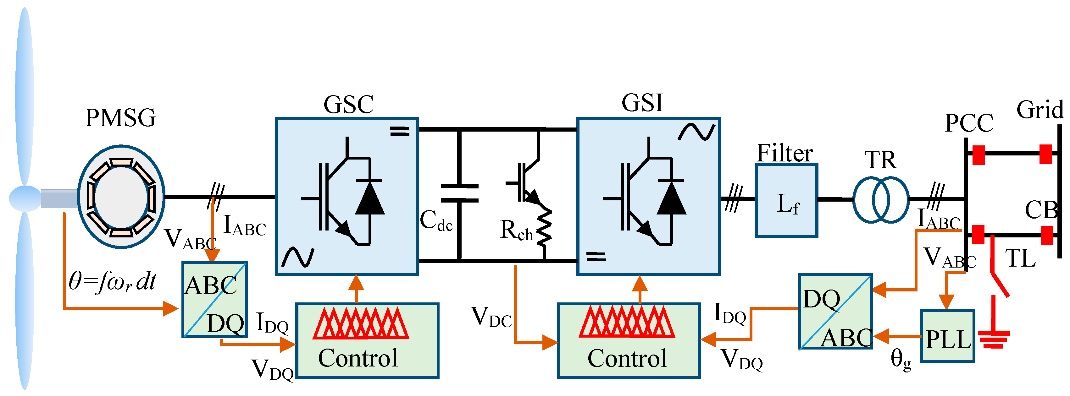
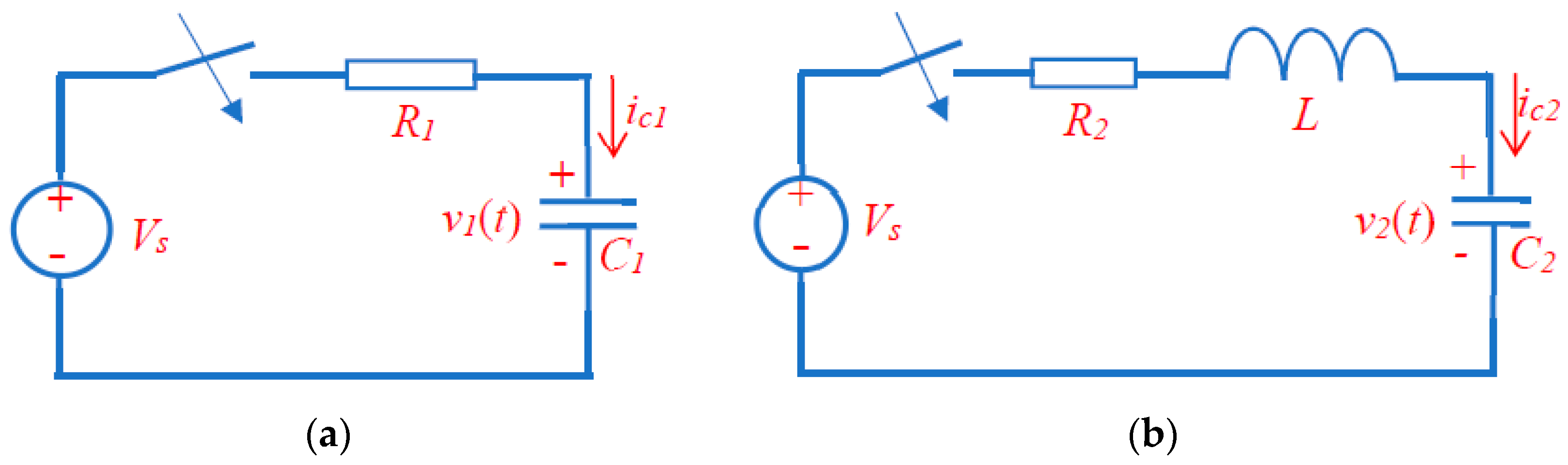
2. Power System Modeling

In this study, the wind power harvesting, conversion, and supply to the electrical grid are modeled as depicted in Figure 1. This model consists of a three-bladed horizontal-axis wind turbine (WT), which harvests the kinetic energy of wind and converts it into mechanical power. Then, the WT is interconnected directly (without gearbox) to the shaft of the PMSG, which will convert the mechanical power to electrical power. However, the rotor side’s rotation speed is deficient, so the frequency converter links the generator and the grid sides. The GSC converts the AC power into DC power, where the DC link capacitor (Cdc) and a chopper resistor (Rch) exists. The GSI converts the DC power to AC power, which is delivered to the electrical grid through inductance filter (Lf), a step-up transformer, and double-circuit overhead transmission lines (TLs). The control system synchronizes the rectifier and the inverter with the voltage and frequency on each side. The data of the power system are listed in the Appendix A.

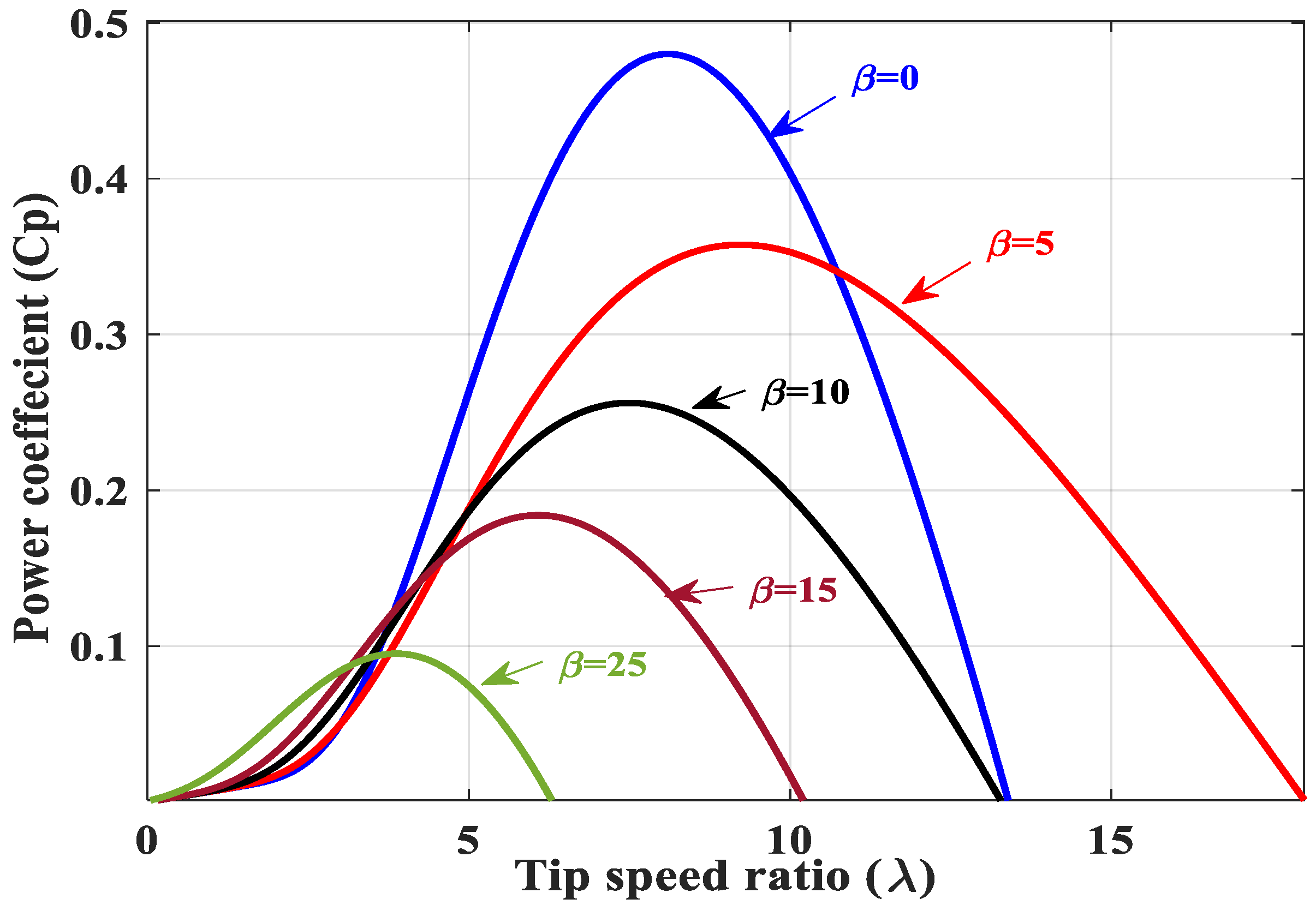
2.1. Horizontal-Axis WT Modeling

A horizontal-axis three-bladed wind turbine is the most widespread type of wind turbine, where the generator is placed on the top of the tower. The airflow is with density ρa = 1.225 kg/m3. va is the velocity and the blades have radius (Rb). The kinetic power (Pk) is converted into rotating power (Pr) with efficacy called power coefficient (Cp) as in Equation (1). However, the efficacy of WT is limited by the Betz constant (0.593) [33].
C p = P r P k
P k = 0.5 ρ a ( π R b 2 ) v a 3
P r = T r ω r
where Tr is the rotor torque, and ωr is the rotor speed. Cp is expressed in Equation (4), where its variables are the tip-speed ratio (TSR λ) and pitch angle (β) of three-blades. Cp is plotted against λ at different values of β, as depicted in Figure 2, where the peak value of Cp occurs at β = 0. Additionally, the rotor power and maximum power (Pmax) are expressed in Equations (7) and (8). Figure 3 shows the rotor power variations and the locus of maximum power versus the rotor speed at different wind speed values [34].
C p ( λ , β ) = 0.5176 ( 116 γ 0.4 β 5 ) e 21 γ + 0.0068 λ
γ = 1 λ + 0.08 β 0.035 1 + β 3
λ = ω r × R b v a
P r = 0.5 ρ a ( π R b 2 ) C p ( λ , β ) v a 3
P max = 0.5 ρ a i r A b C p max ( ω m R λ max ) 3

2.2. Gearless Shaft Modeling

The shaft of PMSG is interconnected to the wind turbine’s shaft without a gearbox, so the rotor speed is low, resulting in a low frequency in the electrical side of PMSG. Therefore, the frequency converter is applied to convert the low frequency to the grid frequency. On the other hand, the frequency converter reduces the grid stresses to the PMSG. A single shaft model can then be used to model the shafts of wind turbines and PMSG, as in Equation (9) [35].
j s d ω r d t + D s ω r = T r T g
where Ds is the shaft damping, js is the shaft inertia, and Tg is the generated torque by the PMSG.

2.3. Generator-Side Modeling

The generator converts the rotational power to electrical power, where the input of the generator model is ωr, and its outputs are the stator voltages, as in Equation (10). The generator voltages (vd, vq), currents (id, iq), and inductances (Ld, Lq) are expressed in the direct and quadrature axis (d-q axis) [36].
( v d v q ) = R s ( i d i q ) d d t ( L d i d L q i q ) + ω g ( L q i q L d i d + ψ f )
where Rs is the stator resistor, ωg is the electric generator speed, and the ψf is the rotor flux linked the stator.

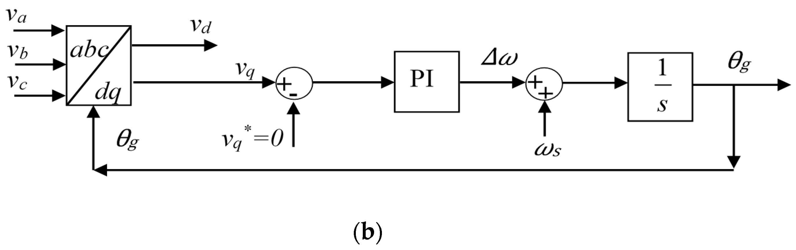
2.4. Grid Side Modeling

In this study, the grid is an extensive power system, which can be modeled by inductance in series with a controlled voltage source. The equivalent inductance (Lg) represents the inductances of the filter, transformer, and TLs. The terminal voltages at the GSI (vid, viq) are expressed in terms of the grid currents (igd, igq) and grid voltages (vgd, vgq) that are measured at the point of common coupling (PCC), as in Equation (11).
( v i d v i q ) = ( v g d v g q ) + L g d d t ( i g d i g q )

3. Frequency Converter Modeling

The frequencies in the generator and grid sides are not synchronized, so the frequency converter is utilized in this study. The frequency converter is constructed from two voltage source converters connected in a back-to-back manner. These converters are based on the insulated gates bipolar transistors (IGBTs) paralleled with diodes. The converter at the generator side, called the GSC, converts the generated AC power to DC power. However, the converter at the grid side, which is called GSI, converts the DC power to AC power that is synchronized with the grid frequency. The IGBTs are switched on and off using pulse width modulation (PWM) signals produced by cascaded control systems of GSC and GSI. The control system consists of four proportional-integral (PI) controllers at each side, so eight PI controllers are used in total. Each PI controller has two parameters (proportional gain (kp) and integral time constant (Ti)).

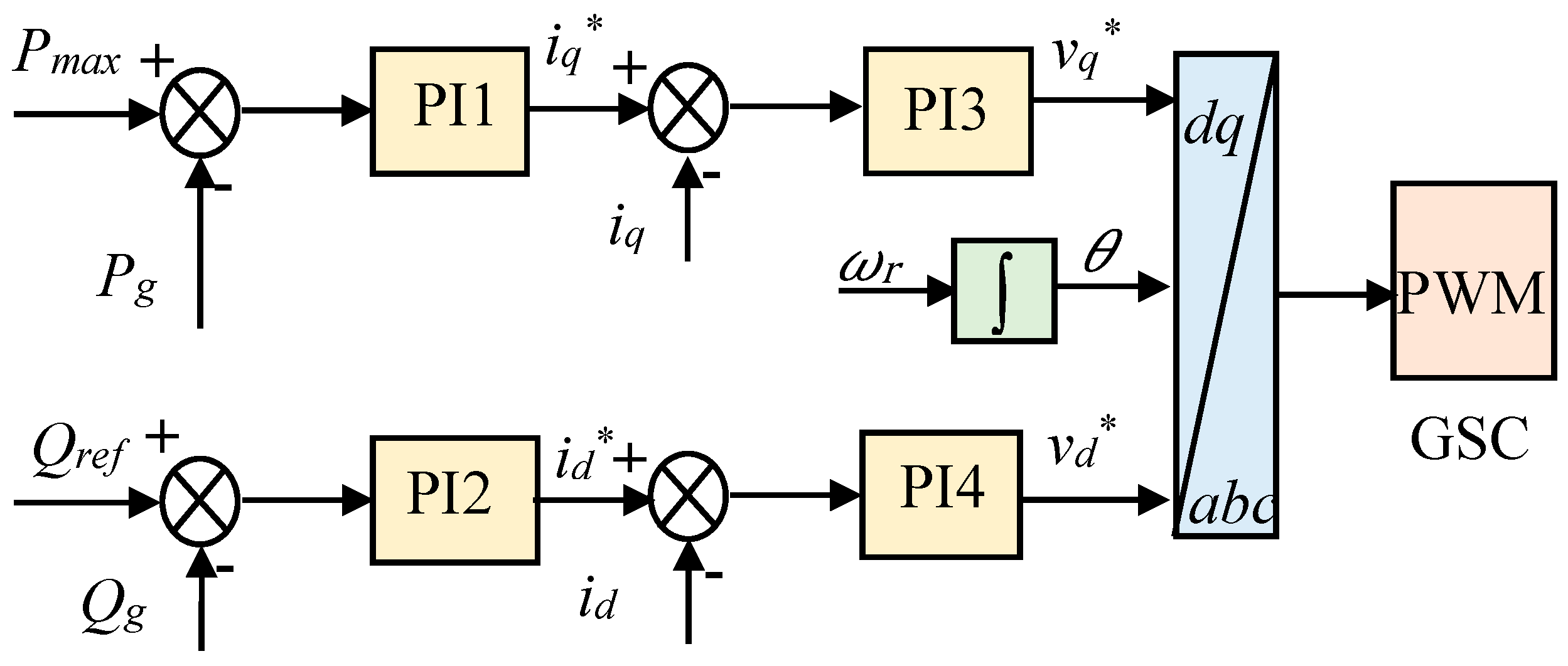
3.1. GSC Control Modeling

The GSC vector control objectives are to obtain i) maximum power point tracking (MPPT) and ii) unity power factor at the generator side. Since Tg is proportional to the iq, as in Equation (12), then the vector control of GSC is a field-oriented control, and the generated real power (Pg) is proportionate with iq, as in Equation (13) [33,36].
T g = 3 2 ( p 2 ) ( λ r i q ( L d L q ) i d i q )
where LdLq, then
P g = ω g T g = 3 2 ( p 2 ) ( λ r i q ) ω g
So, PI1 regulates the Pg with respect to Pmax to generate the reference iq*, as in Equation (14), while PI2 regulates the reactive power (Qg) of generator with respect to the reference Qref to generate the reference id*, as in Equation (15). Consequently, PI3 and PI4 regulate the currents iq, id with respect to iq*, id* to generate the references vq* and vd*, as in Equations (16) and (17). The reference voltage is then transformed using dq-abc transformer, which is synchronized using the phase angle (θ) of PMSG by measuring ωr. So, the cascaded control system of the GSC is depicted in Figure 4.
i q * = k p 1 ( 1 + 1 s T i 1 ) ( P max P g )
i d * = k p 2 ( 1 + 1 s T i 2 ) ( Q r e f Q g )
v q * = k p 3 ( 1 + 1 s T i 3 ) ( i q * i q )
v d * = k p 4 ( 1 + 1 s T i 4 ) ( i d * i d )

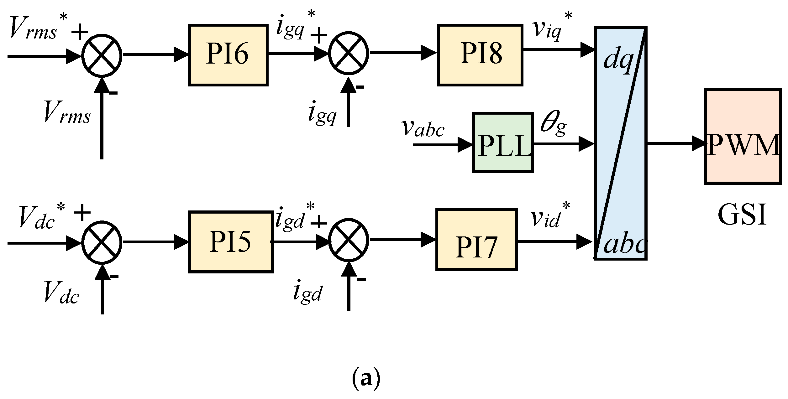
3.2. GSI Control Modeling

The objectives of the control system of the GSI are: i) low voltage ride-through capability enhancement during short circuits by producing reactive power to support stability restoration of the grid, and ii) regulating the DC link voltage to deliver smooth power to the grid. Hence, the DC link voltage (Vdc) is proportionate to the igd, as in Equation (18), PI5 regulates the Vdc with respect to the reference Vdc* to generate the reference igd*, as in Equation (19). Furthermore, PI6 regulates the PCC voltage Vrms relative to the reference voltage Vrms* to create the reference igq*, as in Equation (20). Consequently, PI7 and PI8 regulate the currents igd, igq relative to igd*, igq* to generate the references viq* and vid*, as in Equations (21) and (22), as shown in Figure 5a. Then, the reference voltages are transformed to abc form using dq-abc transformer. The phase-locked loop (PLL) is utilized to produce the phase angle (θg) of the grid for phase synchronization. PLL is based on the dq-frame, where the q-axis voltage is regulated with zero reference, as shown in Figure 5b. In addition, the angular frequency of grid is ωs = 2π × 60 = 377 rad/s.
P g r i d = V d c × I d c = 3 2 v g d × i g d
i g d * = k p 5 ( 1 + 1 s T i 5 ) ( V d c * V d c )
i g q * = k p 6 ( 1 + 1 s T i 5 ) ( V r m s * V r m s )
v i d * = k p 7 ( 1 + 1 s T i 7 ) ( i g d i g d * )
v i q * = k p 8 ( 1 + 1 s T i 8 ) ( i g q * i g q )

4. Optimization Methodology

This study’s main objective is to improve the low voltage ride-through ability of the grid-linked PMSG-based WT. This objective can be achieved by designing optimal PI controllers that exist in the control system. However, as shown in Figure 1, the power system is a big nonlinear dynamic system, which cannot be represented by a transfer function. Therefore, the objective function is considered the sum of the integral of PI controllers’ squared errors (Equation (23)). The stochastic optimization algorithms are applied to design PI controllers’ optimal parameters (kp and Ti) by executing the modeled power system using PSCAD/EMTDC software, as depicted in the flowchart in Figure 6. The power system model’s simulation time is 10 s, and a balanced fault is applied at t = 5 s, with a duration of 0.15 s. In this study, the TSO and GWO algorithms are utilized in minimizing the objective function.
I S E ( x 1 ,   x 2 ,   ,   x 16 ) = 0 10 [ ( P max P g ) 2 + ( Q r e f Q g ) 2 + ( V d c * V d c ) 2 + ( V r m s * V r m s ) 2     + ( i q * i q ) 2 + ( i d * i d ) 2 + ( i g d * i g d ) 2 + ( i g q * i g q ) 2 ] d t
where x1, x2, …, x16 = {kp1, kp2, …, kp8, Ti1, Ti2, …, Ti8}, where 0.01 ≤ kp ≤ 10 and 0.001 ≤ Ti ≤ 1.

4.1. Transient Search Optimization (TSO)

The TSO algorithm is inspired by the transient response of switched electrical circuits that consists of one and two energy storage elements (inductors (L) and capacitors (C)) besides resistors (R), as depicted in Figure 7. The exploration of the TSO algorithm imitates the underdamped transient response of RLC circuits. However, the exploitation of TSO imitates the exponential decay of the transient response of RC circuits. So, the voltage responses across the capacitors in RC and RLC circuits are expressed in Equations (24) and (25).
v 1 ( t ) = v 1 ( ) + ( v 1 ( 0 ) v 1 ( ) ) e t R 1 C 1
v 2 ( t ) = e R 2 t 2 L ( B 1 cos ( 2 π f d t ) + B 2 sin ( 2 π f d t ) ) + v 2 ( )   if   ( R 2 / 2 L ) 2 < 1 / L C 2
where fd is the damping frequency, and B1 and B2 are constant numbers.
Therefore, the main frame of the Equations (24) and (25) is exploited to mode the TSO algorithm mathematically, as in Equation (26). However, the resistors, capacitors and inductor (R1, R2, C1, C2, and L) in Equations (24) and (25) are replaced with random numbers, such as (W and A), that are suitable for metaheuristic algorithms. The variables of TSO algorithm are the search agent Xl+1 and Xl, which are equivalent to the variables v(t) and v(0) in Equations (24) and (25). Additionally, the variable X* is the best agent, which is equivalent to the v(∞). In addition, B1 = B2 = |XlW.Xl*|, where W is expressed as W = k × r2 × a + 1, k is a real number, a = 2 − 2 × l/Lmax, Lmax is the total number of iterations, and r2 is a random number between 0 and 1. The exploration and exploitation of TSO are balanced by using a random number r1.
X l + 1 = { X l * + ( X l W . X l * ) e A r 1 < 0.5 X l * + e A [ cos ( 2 π A ) + sin ( 2 π A ) ] | X l W . X l * | r 1 0.5
where, A = 2 × a × r3a, and r3 are real random numbers between 0 and 1. The pseudo-code of the TSO algorithm is illustrated in Algorithm 1.
Algorithm 1 Transient search optimization (TSO)
Input the random initial values of search agents Xl = {kp1, kp2, …, kp8, Ti1, Ti2…., Ti8} between 0.01 ≤ kp ≤ 10 and 0.001 ≤ Ti ≤ 1
Calculate the ISE(Xl)
while l < Lmax
   Modify A and W
   do all search agents Xl
    Update the search agents by Equation (26)
   end do
   Compute the ISE(Xl+1)
  Compare the ISE(Xl) with ISE(Xl+1) and find the new best search agents X*
l = l + 1
end while
return the best search agents X*

4.2. Grey Wolf Optimizer (GWO)

The GWO is inspired by the leader and followers’ behavior in the group of the grey wolves [37]. There are main leaders (called α) and secondary leaders (called β), and followers (called δ). Grey wolves start the hunting procedure searching for the food, then surround the prey, and then attack the target. So, the mathematical expression of surrounding the food is:
D = | C . X * X l |
X l + 1 = X * A . D
where X is the grey wolf position, X* is the food position, a = 2 − 2l/Lmax, A = 2ar1a, C = 2r2, r1, and r2 are real numbers that are randomly distributed between 0 and 1.
The variables of the GWO algorithm are the search agent Xl and Xl+1 and the best position Xα, however, the constants are a, C and A. The leaders’ Xα start attacking the prey and are supported by the secondary leaders’ Xβ and the followers’ Xδ, where the attacking process is modeled (Equations (29)–(31)). The pseudo-code of the GWO algorithm is explained in Algorithm 2.
D α = | C 1 . X α l X l | ,   D β = | C 2 . X β l X l | ,   D δ = | C 3 . X δ l X l |
X 1 = X α l A 1 . D α ,   X 2 = X β l A 2 . D β ,   X 3 = X δ l A 3 . D δ
X l + 1 = X 1 + X 2 + X 3 3
Algorithm 2 Grey wolf optimizer (GWO)
Input the random initial values of search agents Xl = {kp1, kp2, …, kp8, Ti1, Ti2 …, Ti8} between 0.01 ≤ kp ≤ 10 and 0.001 ≤ Ti ≤ 1
Compute the ISE(Xl)
while l < Lmax
   Modify a, A, and C
   for All search agents
    Update the search agent (Xl+1) by Equation (31)
   end for
   Compute the ISE(Xl+1)
  Compare ISE(Xl+1) with ISE(Xl)and update Xα, Xβ, and Xδ
l = l + 1
end while
Output best search agent Xα

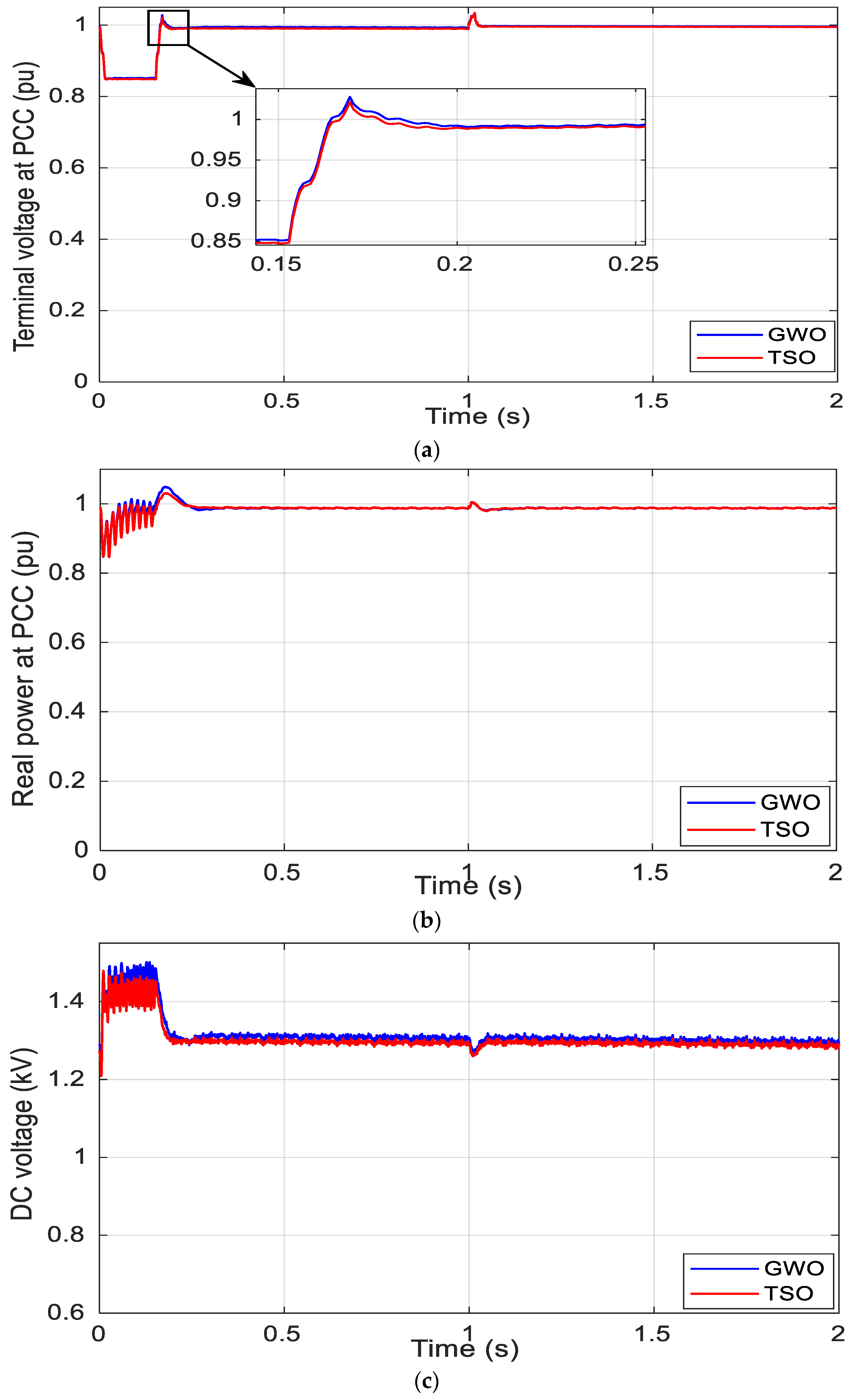
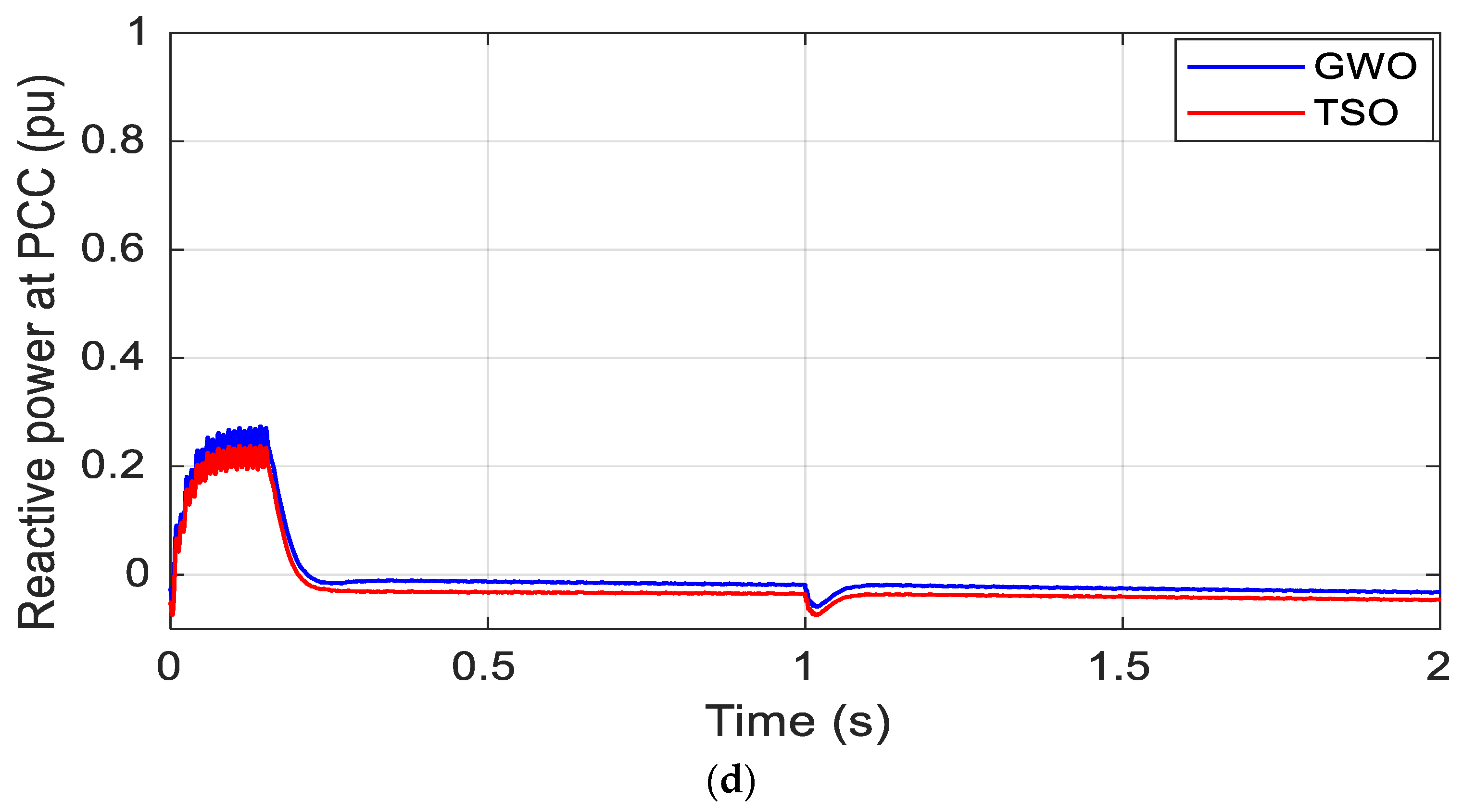
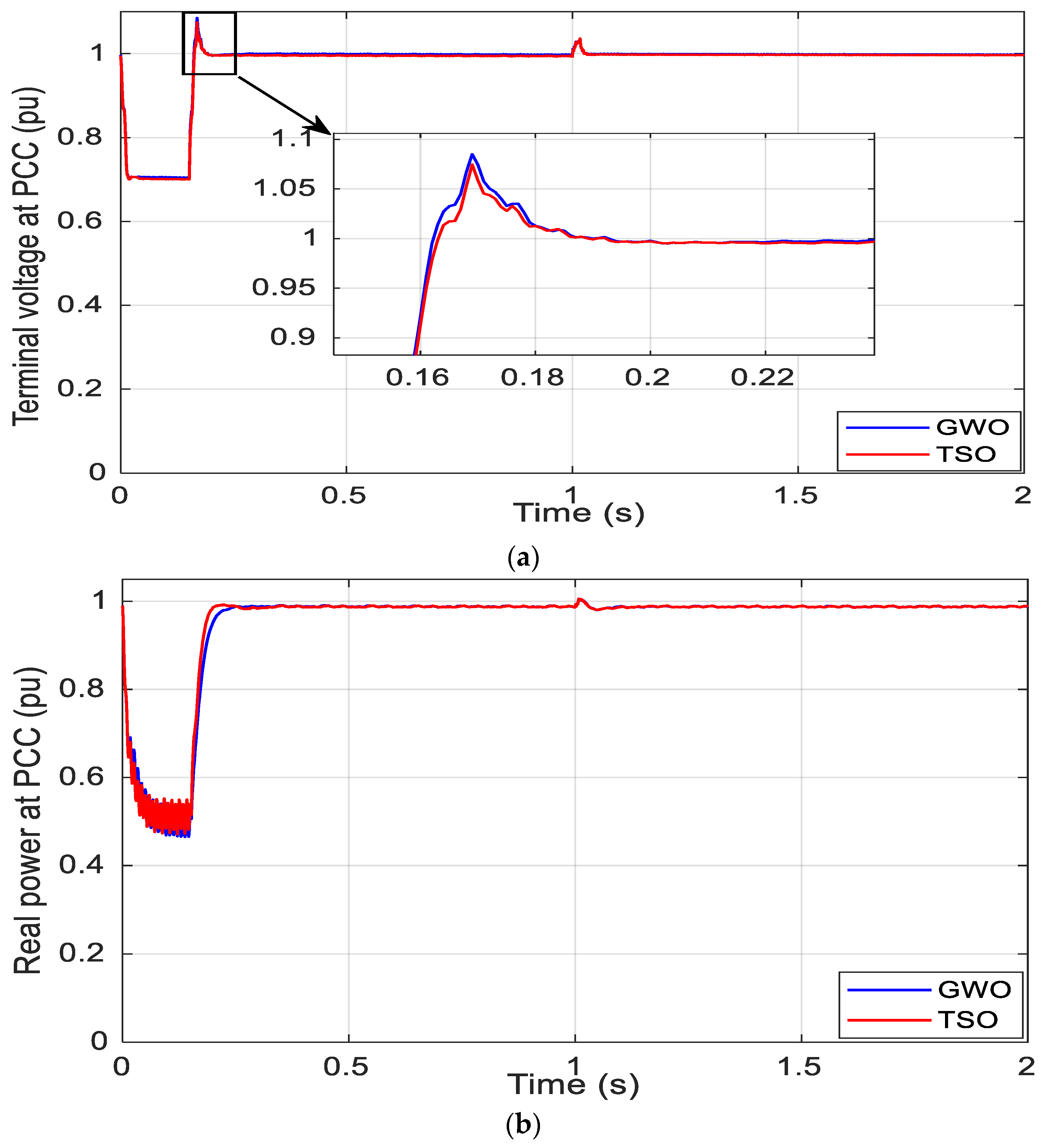
5. Results and Discussion

5.1. Optimization Results

The TSO and GWO are applied to find the PI controllers’ optimal variables by minimizing the objective function in Equation (23). These algorithms are coded using FORTRAN and implemented in PSCAD to design the optimal PI controllers. The parameters of TSO and GWO are set as shown in Table 1, where the number of optimization iterations is 1000 for each algorithm and the simulation time of each iteration is 10 s. Additionally, the balanced fault is considered during optimization to emphasize enhancing the low voltage ride-through (LVRT) ability of grid-linked PMSG-based WT. Hence, Figure 8 illustrates the convergence curves of the integral squared-error (ISE) minimization by using TSO and GWO, where the TSO algorithm has achieved a lower ISE value (0.25953) than the ISE value (0.27269) of the GWO algorithm. In addition, Table 2 and Table 3 show the optimal 16 variables of eight PI controllers that are optimally based on TSO and GWO.

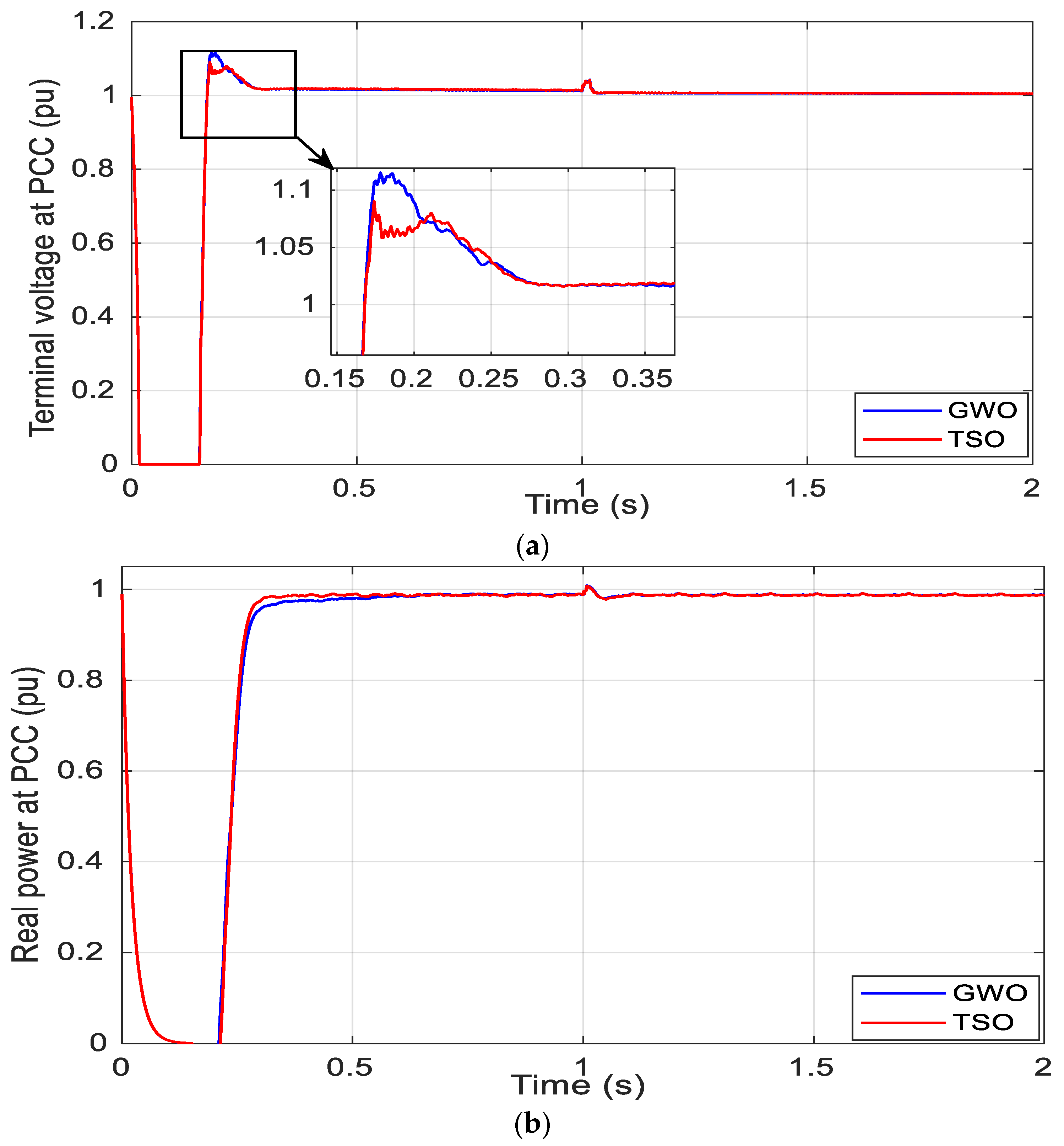
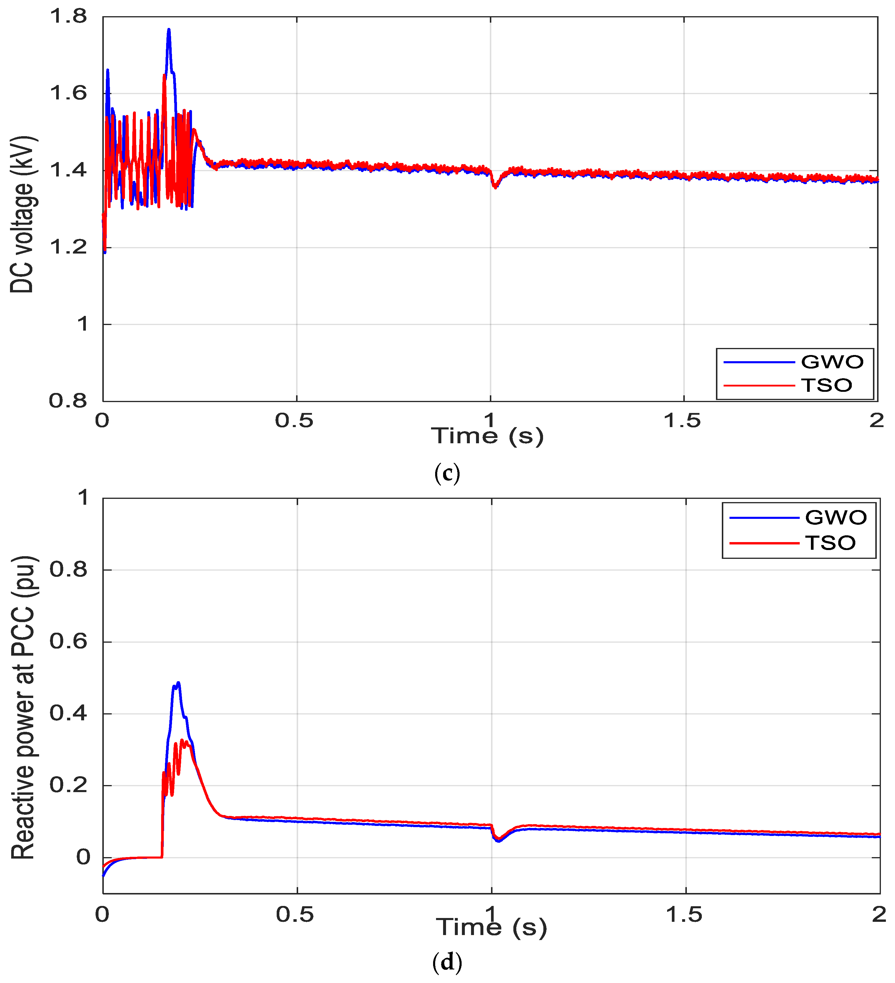
5.2. Simulation Results

In this section, the LVRT ability of the optimal TSO–PI and GWO–PI controllers is tested under balanced and unbalanced short circuits. These abnormal conditions are simulated and applied to the power system model in PSCAD/EMTDC, where the time step is 20 µs.
Case 1, balanced short circuits: This means that TL’s three-phase lines are short-circuited together with ground, which is called three-phase to ground fault (3PGF). This fault occurs at the PCC bus bar at the end of one circuit of the double-circuit TLs, as depicted in Figure 1. The power system model is operating under steady state before the fault occurs at t = 0 s, the circuit breakers (CBs) trip the short-circuited TL after 0.15 s.
Firstly, a temporary balanced short circuit is assumed (e.g., flashover, arc, …, etc.), so the CBs are assumed to reclose at t = 1 s, as depicted in Figure 9. The transient response of Vrms at the PCC bus bar is depicted in Figure 9a, which changes from 1 (pu) at steady state to 0 during the effect of the 3PGF, then returns to the steady-state value once a fault is cleared. During CBs reclosing, the voltage recovery is combined with adverse overshoot and oscillates around the steady-state value until it reaches this value. Therefore, the TSO–PI controllers have attained a lower overshoot than that of the GWO–PI controllers; however, they have the same steady-state error. Figure 9b depicts the real power response during 3PGF, which decreases to 0 during fault at PCC, then recovers to the steady state after fault clearance. Figure 9b shows that the TSO–PI recovers the power faster than the GWO–PI.
Furthermore, the DC link voltage increases during fault due to the excessive power in the DC link, so an adverse overvoltage occurs across the DC capacitors and can be damaged. These capacitors are protected using chopper circuits, as in Figure 1. Additionally, the control system regulates the DC voltage across the capacitors. Figure 9c illustrates that the TSO–PI controller has attained an overvoltage at DC link lower than that of the GWO–PI controller. Moreover, the reactive power at PCC is near the zero value at steady state for a unity power factor correction. Then, after fault clearance, the GSI supports the grid with reactive power to restore the grid stability. Figure 9d shows that reactive power supplied by the TSO–PI controllers is lower than that supplied by the GWO–PI controllers.
Secondly, a permanent balanced short circuit is assumed, so the CBs fail to reclose at t = 1 s, as depicted in Figure 10, then the short-circuited TLs are tripped permanently for maintenance. Figure 10a shows the response of the Vrms measured at PCC during permanent fault and failure of CBs to reclose the tripped TL. The overshoot of TSO–PI controllers is lower than that of GWO–PI during voltage recovery in the first and the second operations of CBs. Moreover, Figure 10b demonstrates the response of real power at PCC during both operations of CBs, where the power response of GWO–PI is much slower in the second act of CBs than the first operation of CBs. However, TSO–PI controllers have attained a fast power response during both operations of CBs. In addition, Figure 10c reveals that the overvoltage and oscillations of DC voltage for TSO–PI are lower than that of GWO–PI. Finally, the reactive power supply during voltage recovery by GWO–PI is higher than that of TSO–PI, as depicted in Figure 10d.
Case 2, unbalanced short circuits: single-phase to ground fault (1PGF) and phase to phase fault (PPF) are considered unbalanced short circuits in the TLs of the power system. Temporary unbalanced short circuits are applied at t = 0, and then the CBs isolate the short-circuited TL at t = 0.15 s; finally, the CBs are assumed to reclose the tripped TL at t = 1 s. Firstly, the PCC voltage responses, real power, DC voltage, and reactive power are measured during the applied 1PGF at the end of one TL, as shown in Figure 11. So, the response of Vrms of TSO–PI is slightly lower than that of the GWO–PI, as displayed in Figure 11a. However, the overshoot of real power of GWO–PI is much higher than that of the TSO–PI, as depicted in Figure 11b. Furthermore, the DC voltage response of the GWO–PI is higher than that of the TSO–PI, as depicted in Figure 11c. In addition, the reactive power supply using GWO–PI after fault clearing is much higher than that of the TSO–PI, as depicted in Figure 11d. Secondly, a temporary PPF is applied, and the response of TSO–PI is compared with the response of GWO–PI, as depicted in Figure 12. The Vrms’ response using TSO–PI has a lower rise time than that of the GWO–PI, as shown in Figure 12a. However, the real power response of the TSO–PI is faster than that of the GWO–PI, as depicted in Figure 12b. Additionally, the DC voltage response of the TSO–PI has better damped response, as illustrated in Figure 12c. finally, the reactive response of the TSO–PI is nearly similar to that of the GWO–PI, as depicted in Figure 12d.

6. Conclusions

This paper has proposed a novel application of the TSO algorithm to optimally fine-tune all PI controller gains of the frequency converters of a PMSG-based VSWT. The main purpose of this study is to achieve LVRT capability enhancement of such systems. The TSO is extensively applied to the fitness function, which possesses the sum of the system variables’ squared error. The optimization problem constraints have taken into account all ranges of the controllers’ parameters. The simulation results have proven the high performance and superiority of the proposed TSO–PI controllers to the GWO–PI controllers under balanced and unbalanced network fault conditions. The results using TSO–PI controllers have given an improvement of more than 5% of some quantities of the system under study. The proposed controller’s high performance comes from the proper design of the TSO during the design procedure, which relies on the designer experience. These good and salient achievements shall encourage researchers to use the TSO–PI controllers to enhance several systems’ responses, including renewable energy systems, microgrids, and smart grid systems.

Author Contributions

M.H.Q.: Writing—original draft, Methodology, Software. H.M.H.: Software, Writing—review & editing. S.A.: Conceptualization, Funding acquisition, Supervision. All authors have read and agreed to the published version of the manuscript.

Funding

This research was funded by the deputyship for research & Innovation, “Ministry of Education” in Saudi Arabia IFKSURG-1440-049.

Acknowledgments

The authors extend their appreciation to the Deputyship for Research & Innovation, “Ministry of Education” in Saudi Arabia for funding this research work through the project number IFKSURG-1440-049.

Conflicts of Interest

The authors declare that they have no known competing financial interests or personal relationships that could have appeared to influence the work reported in this paper.

Appendix A

The data of the power system under study are listed in Table A1.
Table A1. Data of grid-linked PMSG-based WT.
WT
Diameter92 m
PMSG ratings
Power5 MVARotor poles150
Voltage (line to line)690 VInertia time3 s
Frequency30 Hzresistor0.01 pu
Xd0.28 puXq0.28 pu
Magnetic flux1.04 pu
Filter
Inductor0.2 mH
Transformer
Low voltage0.69 kVHigh voltage33 kV
Reactance0.08 puFrequency60 Hz

References

  1. Kusch-Brandt, S. Urban Renewable Energy on the Upswing: A Spotlight on Renewable Energy in Cities in REN21’s “Renewables 2019 Global Status Report”. Resources 2019, 8, 139. [Google Scholar] [CrossRef] [Green Version]
  2. IRENA. Renewable Power Generation Costs in 2017. Available online: https://www.irena.org/-/media/Files/IRENA/Agency/Publication/2018/Jan/IRENA_2017_Power_Costs_2018.pdf (accessed on 11 November 2018).
  3. Global Wind Energy Council (GWEC). Global Wind Report Annual Market Update 2019. Available online: https://gwec.net/global-wind-report-2019 (accessed on 12 September 2020).
  4. Atherton, J.; Sharma, R.; Salgado, J. Techno-economic analysis of energy storage systems for application in wind farms. Energy 2017, 135, 540–552. [Google Scholar] [CrossRef] [Green Version]
  5. Rashedi, E.; Nezamabadi-Pour, H.; Saryazdi, S. GSA: A Gravitational Search Algorithm. Inf. Sci. 2009, 179, 2232–2248. [Google Scholar] [CrossRef]
  6. Hur, S.-H. Modelling and control of a wind turbine and farm. Energy 2018, 156, 360–370. [Google Scholar] [CrossRef]
  7. Qais, M.H.; Hasanien, H.M.; Alghuwainem, S. Output power smoothing of grid-connected permanent-magnet synchronous generator driven directly by variable speed wind turbine: A review. J. Eng. 2017, 2017, 1755–1759. [Google Scholar] [CrossRef]
  8. Qais, M.H.; Hasanien, H.M.; Alghuwainem, S. Low voltage ride-through capability enhancement of grid-connected permanent magnet synchronous generator driven directly by variable speed wind turbine: A review. J. Eng. 2017, 2017, 1750–1754. [Google Scholar] [CrossRef]
  9. Mohseni, M.; Islam, S.M. Review of international grid codes for wind power integration: Diversity, technology and a case for global standard. Renew. Sustain. Energy Rev. 2012, 16, 3876–3890. [Google Scholar] [CrossRef]
  10. Hasanien, H.M. An Adaptive Control Strategy for Low Voltage Ride Through Capability Enhancement of Grid-Connected Photovoltaic Power Plants. IEEE Trans. Power Syst. 2015, 31, 3230–3237. [Google Scholar] [CrossRef]
  11. Qais, M.H.; Hasanien, H.M.; Alghuwainem, S. Output power smoothing of wind power plants using self-tuned controlled SMES units. Electr. Power Syst. Res. 2020, 178, 106056. [Google Scholar] [CrossRef]
  12. Kayk, M.; Milanovic, J.V. Reactive Power Control Strategies for DFIG-Based Plants. IEEE Trans. Energy Convers. 2007, 22, 389–396. [Google Scholar] [CrossRef]
  13. Qais, M.H.; Hasanien, H.M.; Alghuwainem, S. A novel LMSRE-based adaptive PI control scheme for grid-integrated PMSG-based variable-speed wind turbine. Int. J. Electr. Power Energy Syst. 2021, 125, 106505. [Google Scholar] [CrossRef]
  14. Soliman, M.A.; Hasanien, H.M.; Al-Durra, A.; Alsaidan, I. A Novel Adaptive Control Method for Performance Enhancement of Grid-Connected Variable-Speed Wind Generators. IEEE Access 2020, 8, 82617–82629. [Google Scholar] [CrossRef]
  15. Qais, M.; Hasanien, H.M.; Alghuwainem, S. Salp swarm algorithm-based TS-FLCs for MPPT and fault ride-through capability enhancement of wind generators. ISA Trans. 2020, 101, 211–224. [Google Scholar] [CrossRef] [PubMed]
  16. Hasanien, H.M.; Muyeen, S. Speed control of grid-connected switched reluctance generator driven by variable speed wind turbine using adaptive neural network controller. Electr. Power Syst. Res. 2012, 84, 206–213. [Google Scholar] [CrossRef] [Green Version]
  17. Ribrant, J.; Bertling, L. Survey of failures in wind power systems with focus on Swedish wind power plants during 1997–2005. 2007 IEEE Power Eng. Soc. Gen. Meet. 2007, 22, 1–8. [Google Scholar] [CrossRef]
  18. Qais, M.H.; Hasanien, H.M.; Alghuwainem, S. Augmented grey wolf optimizer for grid-connected PMSG-based wind energy conversion systems. Appl. Soft Comput. 2018, 69, 504–515. [Google Scholar] [CrossRef]
  19. Soliman, M.; Hasanien, H.; Al-Durra, A.; Debouza, M. High Performance Frequency Converter Controlled Variable-Speed Wind Generator Using Linear-Quadratic Regulator Controller. IEEE Trans. Ind. Appl. 2020, 56, 1. [Google Scholar] [CrossRef]
  20. Qais, M.H.; Hasanien, H.M.; Alghuwainem, S. Whale optimization algorithm-based Sugeno fuzzy logic controller for fault ride-through improvement of grid-connected variable speed wind generators. Eng. Appl. Artif. Intell. 2020, 87, 103328. [Google Scholar] [CrossRef]
  21. Soliman, M.A.; Hasanien, H.M.; Azazi, H.Z.; El-Kholy, E.E.; Mahmoud, S.A. Hybrid ANFIS-GA-based control scheme for performance enhancement of a grid-connected wind generator. IET Renew. Power Gener. 2018, 12, 832–843. [Google Scholar] [CrossRef]
  22. Hasanien, H.M.; Muyeen, S.M. Design Optimization of Controller Parameters Used in Variable Speed Wind Energy Conversion System by Genetic Algorithms. IEEE Trans. Sustain. Energy 2012, 3, 200–208. [Google Scholar] [CrossRef]
  23. Hasanien, H.M.; Muyeen, S.M. A Taguchi Approach for Optimum Design of Proportional-Integral Controllers in Cascaded Control Scheme. IEEE Trans. Power Syst. 2012, 28, 1636–1644. [Google Scholar] [CrossRef] [Green Version]
  24. Hasanien, H.M.; Matar, M. Water cycle algorithm-based optimal control strategy for efficient operation of an autonomous microgrid. IET Gener. Transm. Distrib. 2018, 12, 5739–5746. [Google Scholar] [CrossRef]
  25. Qais, M.H.; Hasanien, H.M.; Alghuwainem, S. A Grey Wolf Optimizer for Optimum Parameters of Multiple PI Controllers of a Grid-Connected PMSG Driven by Variable Speed Wind Turbine. IEEE Access 2018, 6, 44120–44128. [Google Scholar] [CrossRef]
  26. Qais, M.H.; Hasanien, H.M.; Alghuwainem, S. Enhanced whale optimization algorithm for maximum power point tracking of variable-speed wind generators. Appl. Soft Comput. 2020, 86, 105937. [Google Scholar] [CrossRef]
  27. Soliman, M.A.; Hasanien, H.M.; Alghuwainem, S.; Al-Durra, A. Symbiotic organisms search algorithm-based optimal control strategy for efficient operation of variable-speed wind generators. IET Renew. Power Gener. 2019, 13, 2684–2692. [Google Scholar] [CrossRef]
  28. Qais, M.H.; Hasanien, H.M.; Alghuwainem, S. Enhanced salp swarm algorithm: Application to variable speed wind generators. Eng. Appl. Artif. Intell. 2019, 80, 82–96. [Google Scholar] [CrossRef]
  29. Mahmoud, H.Y.; Hasanien, H.M.; Besheer, A.H.; Abdelaziz, A.Y. Hybrid cuckoo search algorithm and grey wolf optimiser-based optimal control strategy for performance enhancement of HVDC-based offshore wind farms. IET Gener. Transm. Distrib. 2020, 14, 1902–1911. [Google Scholar] [CrossRef]
  30. Qais, M.H.; Hasanien, H.M.; Alghuwainem, S. Transient search optimization: A new meta-heuristic optimization algorithm. Appl. Intell. 2020, 50, 3926–3941. [Google Scholar] [CrossRef]
  31. Qais, M.H.; Hasanien, H.M.; Alghuwainem, S. Transient search optimization for electrical parameters estimation of photovoltaic module based on datasheet values. Energy Convers. Manag. 2020, 214, 112904. [Google Scholar] [CrossRef]
  32. M. H. R. Center, “PSCAD/EMTDC Software.” Manitoba, Canada. Available online: https://www.pscad.com/software/pscad/overview (accessed on 24 June 2020).
  33. Hazari, R.; Mannan, M.A.; Muyeen, S.; Umemura, A.; Takahashi, R.; Tamura, J. Stability Augmentation of a Grid-Connected Wind Farm by Fuzzy-Logic-Controlled DFIG-Based Wind Turbines. Appl. Sci. 2017, 8, 20. [Google Scholar] [CrossRef] [Green Version]
  34. Yaramasu, V.; Kouro, S.; Dekka, A.; Alepuz, S.; Rodriguez, J.; Duran, M. Power Conversion and Predictive Control of Wind Energy Conversion Systems; Springer: Singapore, Singapore, 2019; pp. 113–139. [Google Scholar]
  35. Vittal, V.; Ayyanar, R. Grid Integration and Dynamic Impact of Wind Energy; Springer: New York, NY, USA, 2013; pp. 115–144. [Google Scholar]
  36. Wu, B.; Lang, Y.; Zargari, N.; Kouro, S. Power conversion and control of wind energy systems, 1st ed.; John Wiley & Sons: Hoboken, NJ, USA, 2011. [Google Scholar]
  37. Mirjalili, S.; Mirjalili, S.M.; Lewis, A. Grey Wolf Optimizer. Adv. Eng. Softw. 2014, 69, 46–61. [Google Scholar] [CrossRef] [Green Version]
Figure 1. Grid-linked permanent magnet synchronous generator (PMSG) driven by variable-speed wind turbine (VSWT).
Electronics 09 01807 g001
Figure 2. The variations of power coefficient (Cp) versus tip-speed ratio (λ) at different values of pitch angle (β).
Electronics 09 01807 g002
Figure 3. Per unit rotor power variations versus rotor speed at different wind speeds.
Electronics 09 01807 g003
Figure 4. Control system of generator-side converter (GSC).
Electronics 09 01807 g004
Figure 5. Control system of grid-side inverter (GSI), (a) vector control of voltage and (b) phase angle control by phase-locked loop (PLL).
Electronics 09 01807 g005aElectronics 09 01807 g005b
Figure 6. Flowchart of optimization.
Electronics 09 01807 g006
Figure 7. The electrical circuit including (a) one-storage element and (b) two-storage element.
Electronics 09 01807 g007
Figure 8. Convergence of best values of ISE function.
Electronics 09 01807 g008
Figure 9. Point of common coupling (PCC) measurements during temporary three-phase to ground fault (3PGF), (a) Vrms, (b) Pgrid, and (c) VDC, and (d) Qgrid.
Electronics 09 01807 g009aElectronics 09 01807 g009b
Figure 10. PCC measurements during permanent 3PGF, (a) Vrms, (b) Pgrid, and (c) VDC, and (d) Qgrid.
Electronics 09 01807 g010aElectronics 09 01807 g010b
Figure 11. PCC measurements during temporary single-phase to ground fault (1PGF), (a) Vrms, (b) Pgrid, and (c) VDC, and (d) Qgrid.
Electronics 09 01807 g011aElectronics 09 01807 g011b
Figure 12. PCC measurements during temporary phase to phase fault (PPF), (a) Vrms, (b) Pgrid, and (c) VDC, and (d) Qgrid.
Electronics 09 01807 g012aElectronics 09 01807 g012b
Table 1. Parameters settings of transient search optimization (TSO) and grey wolf optimization (GWO).
AlgorithmParameters of Algorithms
TSOLmax = 1000, k = 1, a ϵ [2, 0], dimensions = 16, no. of population = 10
GWOLmax = 1000, a ϵ [2, 0], dimensions = 16, no. of population = 10
Table 2. Optimal variables of the proportional-integral (PI) controllers of GSC control.
PI1PI2PI3PI4
kpTikpTikpTikpTi
TSO2.0146440.0179841.0112080.0171225.0385110.9985111.0123400.020618
GWO2.0281260.0202851.1096510.2148171.6240010.4161610.6678450.186149
Table 3. Optimal variables of PI controllers of GSI control.
PI5PI6PI7PI8
kpTikpTikpTikpTi
TSO3.3126420.0648598631.0329790.8629916.0068390.0010153.7550120.008518
GWO1.1887070.9935250.0657290.8779693.1814360.1401092.4680100.001349
Publisher’s Note: MDPI stays neutral with regard to jurisdictional claims in published maps and institutional affiliations.

