Abstract
The wireless power transfer (WPT) system via coupled magnetic resonance (CMR) is an efficient and practical power transmission technology that can realize medium- and long-distance power transmission. People’s requirements for the flexibility of charging equipment are becoming increasingly prominent. How to get rid of the “flitch plate type” wireless charging method and enhance the anti-offset performance is the main research direction. Directional characteristics of the system can affect the load receive power and system efficiency in practical applications. In this paper, the power and efficiency of the WPT system via CMR were analyzed according to the principle of near-field strong coupling at first. The expression of the mutual inductance between the transmitting and the receiving coils under angular offset was derived from the perspective of the mathematical model, and the influences of angular deviation were analyzed. Second, simulation models were established under different distance between coils, different coil types, and different coil radius ratios in symmetrical and asymmetrical systems. Afterwards, the directional law was obtained, providing reference for the optimal design of coupling coils. Finally, an experimental system was built, and directional characteristic experiments were carried out under different conditions. Experimental results were consistent with simulation results, which verified the theoretical analysis.
1. Introduction
Wireless power transmission (WPT), which is also called contactless power transmission (CPT), is not only widely used in the fields of electric vehicles, mobile devices, etc., but also has research values and practical significance for the development of electromagnetic theory [1,2,3,4,5,6]. In 2007, scholars at the Massachusetts Institute of Technology (MIT) proposed the principle of a WPT system via coupled magnetic resonance (CMR) and successfully light up a 60 W bulb at a distance of 2 m, with a transmission efficiency of 40–50% [7,8]. Compared with microwave radiation [9] and magnetic induction [10], CMR has advantages of large transmission power, long energy transmission distance, flexibility, and safety. Therefore, the CMR has become a research hotspot in this field.
Wireless power transmission technology has changed the situation that the consumer electronics field has always relied on charging wires and plugs. The application of this technology has become a mainstream trend and has been applied to major consumer electronics brand manufacturers in the world [11,12,13]. At the same time, how to get rid of the “flitch plate type” wireless charging method and enhance the anti-offset performance is also a future research direction. Even if the system of WPT with CMR has a certain degree of non-directionality, it can reduce the system’s requirements for directionality to a certain extent, but there is no definite standard for the non-directional range of the system in practical applications. At present, most researches on the CMR system focus on how to improve the system’s transmission efficiency or realize the high-power and long-distance transmission. For example, a variety of ways were adopted to optimize impedance matching so as to increase power [14,15]. In [16,17], relay coils or coil arrays were used to increase the transmission distance. In [18,19], the parameters of coupling coils were optimized to improve the system efficiency. These researches were mainly aimed at the transmitting and receiving coils that were parallel to each other, while the directivity of the corresponding coils did not change and the parameters were also the same. However, it is required that the directivity of coupling coils should not change, especially under many practical application scenarios such as household appliances, medical implantation and electric vehicle charging.
According to market needs, more and more attention has been paid to the research of wireless power transmission in three-dimensional space based on non-directional and some research results have been obtained. The article [20] designed a deformable launch mechanism based on the directionality of the system, which can achieve a higher degree of freedom of the magnetic field, but this method has a certain degree of uncontrollability. In the article [21], a bowl-mounted launch mechanism is proposed, which can basically achieve “non-directional” within the charging range, but it does not indicate the specific anti-offset standard. The article [22] proposes an anti-offset charging system similar to the shape of joints, but there are space limitations. The article [23] uses Helmholtz coils to design a three-dimensional transmitting mechanism and realizes omnidirectional wireless charging, but the directional attenuation range is not regulated. Therefore, it is very necessary to analyze the directivity of the CMR with WPT system.
The directivity of a coupling coil can be expressed by the angular deviation of a coaxial receiving coil. It is reported that the CMR system can be almost “non-directional” in [24]. However, [24] did not give a specific explanation from the perspective of simulations or experiments, nor did it analyze the directional characteristics. In [25], formulas were given to calculate the axial distance, radial distance, deflection angle, and the mutual inductance between arbitrary transmitting and receiving coils at any position in a space. However, the WPT technology was not combined to analyze the related transmission characteristics. In [26], the influences of transverse shift of the coil on the system efficiency and power were analyzed without the consideration of the coil’s directionality. In [27], a novel model of the MCR WPT system was established, which took into account the transverse shift of the coil when analyzing the output voltage and transmission efficiency. Note that the angular deviation of coupling coils were not considered in [26] or [27]. At the same time, the current research does not quantitatively analyze the directionality of the CMR system.
In this paper, a quantitative analysis of the directivity of coupled coils was carried out. First, a mathematical model was established for the WPT system with angular deviation. Second, the law of directionality for a symmetrical and an asymmetrical WPT system were obtained through simulations, providing reference for the optimal coil design. Finally, an experimental platform was built to verify simulation results.
2. Analysis of Angular Deviation of WPT System
2.1. Description on CMR-WPT System
The WPT system via CMR mainly includes an RF power source, an electromagnetic launch system, an electromagnetic receiving system, and load, as shown in Figure 1, where D is the distance between the center points of transmitting and receiving coils; k is the coupling factor between coils; and θ is the deviation angle of the receiving coil. Since this system works at MHz, a four-coil structure is adopted to reduce the influences of power supply and load circuit on the resonance frequency of the transmitting and receiving coils [8,28]. Both the source and load coils are of single-turn, which are closely arranged with the transmitting and receiving coil, respectively. The transmitting and receiving coils can achieve efficient energy transmission through “resonant coupling”.
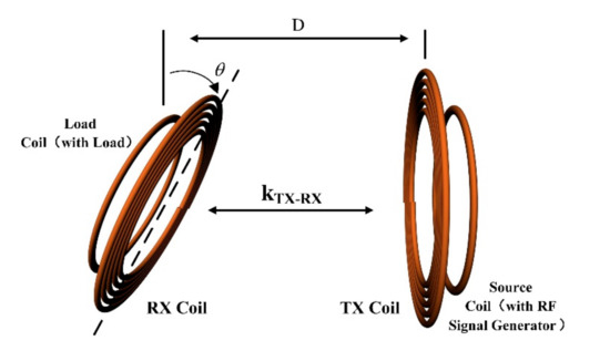
Figure 1.
Schematic of wireless power transfer (WPT) system.
In order to simplify calculations, the circuit of the source coil is reflected into the circuit of the transmitting coil, which is equivalent to adding an induced electromotive force with certain impedance to the transmitting coil. Similarly, the circuit of the load coil is reflected into the circuit of the receiving coil, which is equivalent to adding a reflection impedance to the receiving coil. The equivalent circuit is shown in Figure 2, where Us is excitation voltage; RL is load impedance; Ls and LD are the inductances of transmitting and receiving coils, respectively; M is mutual inductance; R1 and R2 are the impedances of the transmitting and receiving coils, respectively; and Cs and CD are the capacitances of the transmitting and receiving systems, and include a parasitic capacitance and a tuning capacitor, respectively.
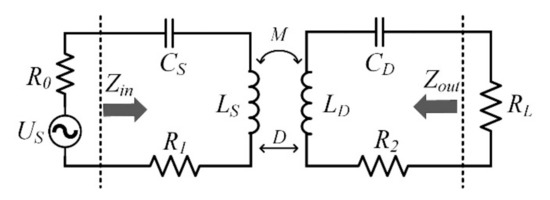
Figure 2.
Equivalent circuit of WPT system.
Assume that the inductances of the transmitting and receiving coils are identical. Meanwhile, the tuning capacitances of the transmitting and receiving systems are the same, i.e., LS = LD, and CS = CD. The radiation loss and power loss of the energy transfer system can be ignored. When the system is in resonance, the impedance of each coil is pure resistance. According to the Kirchhoff’s theorem, the expressions of load receive power and system efficiency can be obtained as:
2.2. Influences of Angular Deviation
According to Formulas (1) and (2), it can be seen that the power and efficiency of the CMR system change with the changes in M and the resistance of load, as shown in Figure 3. The load resistance value is set to 50 Ω, which is the default characteristic of most high-frequency systems. In the simulations, the power supply voltage Us = 100 V, the frequency f = 6.78 MHz, and R1 = R2 = 3.76 Ω. As can be seen from Figure 3, the power first increases and then decreases, while the efficiency gradually decreases with the decrease in M.
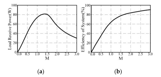
Figure 3.
Transmission characteristics vs. mutual inductance. (a) Load receive power. (b) System efficiency.
M will change when the deviation angle of the receiving coil changes, thereby affecting the system’s power and efficiency. When the transmitting and receiving coils are at any position in a space, the relationship between M and different coil parameters can be expressed by the Neumann’s formula,
where N1 and N2 are the turns of the transmitting and receiving coils, respectively; l1 and l2 are the lengths of each turn of the transmitting coil and that of the receiving coil, respectively; μ0 is the permeability of vacuum; and r12 is the distance between dl1 and dl2. The deviation of the receiving coil angle is shown in Figure 4a. The expressions of dl1 and dl2 can be calculated as follows.
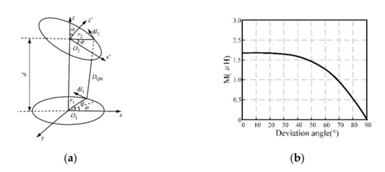
Figure 4.
(a) Model of angular deviation. (b) Mutual inductance vs. deviation angle.
By substituting Formula (4) into Formula (3), we can obtain the relationship of the coupling coil’s mutual inductance with the deviation angle:
According to Formula (5), the relationship between the mutual inductance and the deviation angle of the receiving coil can be obtained, as shown in Figure 4b. It can be seen that M gradually decreases as the deviation angle increases. Specifically, when the deviation angle reaches 90°, M is 0.
Through theoretical analysis, it can be found that the load receiving power and system efficiency decrease with the increase in the deviation angle of the receiving coil. In addition, there is no power receiving load when the two coils are perpendicular.
3. Simulation Analysis
3.1. Establishement of Simulation Model
Considering that there are many factors that affect the load receive power and system efficiency, the multi-physics simulation software COMSOL is used to build a WPT system model. By adjusting the deviation angle of the coil based on the center of the receiving coil, the influences of deviation angle on the system’s power and efficiency are explored. The model’s outer layer is set as the air domain, and the perfectly matched layer is used to simulate the experimental environment, in which electromagnetic waves propagate infinitely during power-on. The lines of magnetic induction and electricity intuitively represent the magnetic field distribution in the simulated space. The coil types used in this paper include flat spiral, square, and solenoid, as shown in Figure 5. The outer diameter of the flat spiral coil, the outer side length of the released square coil, and the diameter of the solenoid are all equal to r. According to the difference between the transmitting and receiving coils in simulations, there are two types of WPT systems, i.e., symmetrical and asymmetrical. The parameters of a symmetrical system are listed in Table 1. In comparison, in an asymmetric system, the radius of the receiving coil or the coil type changes.
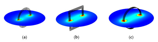
Figure 5.
Simulation models. (a) Flat spiral coil. (b) Square coil. (c) Solenoid.

Table 1.
Parameters of Symmetrical WPT System.
3.2. Simulation of Symmetrical System
In the simulations, by fixing the deviation angle of the transmitting coil while changing that of the receiving coil, the influences of different deviation angles on the WPT system’s power and efficiency are explored. First, the tuning capacitor value is scanned in series with the coil while keeping the system resonate at 6.78 MHz. The tuning capacitors of the flat spiral coil system, solenoid system and square coil system are 28.81 pF, 21.6 pF, and 22.18 pF, respectively, and the load is 50 Ω. Then, the load receive power and system efficiency at different distances can be obtained by “parametric scanning” of the distance between coupling coils in COMSOL. The simulation results with three different coil types are shown in Figure 6.
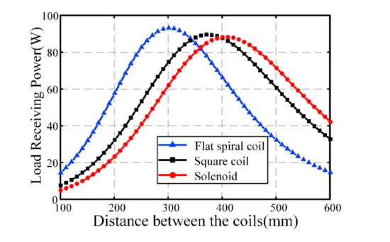
Figure 6.
Load receive power of three systems with different types of coil at different distances.
From Figure 6, it can be seen that the load receive power of the three systems increase first and then decrease as the distance between the receiving and transmitting coils becomes longer. The load receive power reaches its peak when the distance between coupling coils reach a certain value, which is defined as the critical coupling distance. The critical coupling distances of the flat spiral coil system, square coil system and solenoid system are 302 mm, 376 mm and 408 mm, respectively. The distance shorter than the critical value is defined as the over-coupling distance, while that longer than the critical value is defined as the under-coupling distance.
The deviation angle of the receiving coil is scanned parametrically at the critical coupling distance, over-coupling distance and under-coupling distance. The influences of deviation angle on the WPT system in different distance ranges are shown in Figure 7.
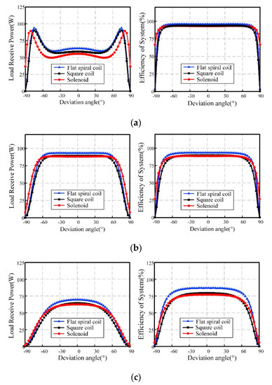
Figure 7.
(a) Angular deviation at 0.7 times the critical coupling distance. (b) Angular deviation at critical coupling distance. (c) Angular deviation at 1.3 times the critical coupling distance.
In general, the load receive power of the WPT system gradually decreases with the increase in deviation angle. However, the load receive power increases first and then decreases with the increase in the deviation angle within the range of over-coupling distance, as shown in Figure 7a. The system efficiency shows a downward trend with the growing deviation angle, but it remains stable within a certain range.
To further determine the load receiving power, we can observe the changes in magnetic field at different deviation angles in the range of over-coupling distance. A flat spiral coils system is taken as an example, and the module value of magnetic flux density (T) is shown in Figure 8, where the magnetic field strength does not change significantly around the receiving coil when the deviation angle is 30°, but is significantly enhanced at 60°. Moreover, there is no magnetic field around the receiving coil at 90°, proving that the load receive power increases first and then decreases with the growing deviation angle in the range of over-coupling distance.
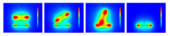
Figure 8.
Magnetic flux density with different angular deviations in symmetrical system.
In order to show that the system efficiency can remain stable within a certain range of deviation angle, the degree of decrease in system efficiency is observed at different distances when the deviation angles are 65°, 75°, and 85°, respectively.
From Figure 9, it can be seen that when the offset angle is 65°, the system efficiency drops by 0.47% when the distance between coupling coils is in the range of over-coupling distance. The system efficiency drops by 3.17% at the critical coupling distance, and by 12.26% at the under-coupling distance, showing that the longer the distance, the faster the efficiency drops at the same deviation angle. The system efficiency decreases by 1.71% when the deviation angle of the receiving coil increases from 65° to 75°, with the distance being 211.4 mm. This shows that the system efficiency can remain stable within a certain range of deviation angle range; the closer the coupling coil, the larger the deviation angle range for a stable efficiency.
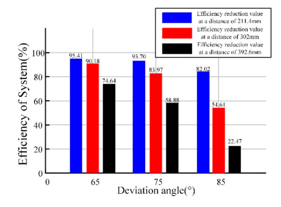
Figure 9.
Degree of decrease in system efficiency.
3.3. Simulation of Asymmetrical System
3.3.1. Asymmetric Systems with Different Radius Ratios
In the simulations, the coupling coils of the asymmetric WPT system adopts a structure of flat spiral coils, with different radiuses of the transmitting and receiving coils. The simulation parameters are consistent with those listed in Table 1. When changing the radius of the receiving coil, the tuning capacitance of the receiving coil needs to be adjusted so that the system can maintain resonance at 6.78 MHz. The radius ratio and the tuning capacitance of the corresponding receiving coils are listed in Table 2. The relationship among the deviation angle of the receiving coil, load receive power, and system efficiency at different receiving coil radius ratios are shown in Figure 10.
Table 2.
Radius ratios and values of the corresponding capacitance.
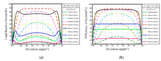
Figure 10.
Simulation results at different radius ratios. (a) Load receive power vs. deviation angle. (b) Efficiency of system vs. deviation angle.
From Figure 10a, it can be seen that the load receive power of the system is maximum when the coupling coils are symmetrical and parallel to each other. When the radius of the receiving coil is larger than that of the transmitting coil, the load receive power stabilizes within a certain range of deviation angle first, and then decreases with the growing deviation angle.
This is similar to the changing law for load receive power of the coupling coils at the over-coupling distance in a symmetrical system. When the radius of the receiving coil is shorter than that of the transmitting coil, the load receive power will gradually decrease after being stabilized within a certain range of deviation angle. The larger the radius difference, the smaller the deviation angle range that is required to keep the load receive power stable. Taking the radius of the transmitting coil of 200 mm and the radius of the receiving coil of 320 mm as an example. In the simulation, the phenomenon that the received power of the load increases first and then decreases as the angle increases can be intuitively expressed by observing the change of magnetic flux density (T), as shown in Figure 11.
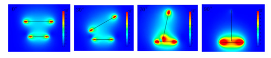
Figure 11.
Magnetic flux density with different angular deviations in asymmetrical system.
From Figure 10b, it can be seen that the system efficiency gradually decreases after being stable within a deviation angle range with the increase in deviation angle. At the same time, the larger the receiving coil, the longer the deviation angle range in which the system efficiency can be kept stable.
3.3.2. Asymmetric System with Different Coil Types
In the CMR system, the transmitting and receiving coils resonate with each other to transfer energy. Therefore, by fixing the transmitting coil and using different types of coil as the receiving coil, the energy can be transmitted by adjusting the resonance frequency. In the simulations, the coil types are divided into flat spiral, square, and solenoid. In total, there are six combinations. In addition, the resonance frequency is still set to 6.78 MHz. The value of tuning capacitance and the critical coupling distance of the WPT system are listed in Table 3 under these combinations.
Table 3.
Critical coupling distance and tuning capacitance of system under different coil combinations.
The distance between the transmitting and receiving coils is set as the critical coupling distance, and the system load is 50 Ω. By changing the deviation angle of different types of receiving coil, the load receive power and system efficiency can be observed, as shown the Figure 12. From this comparison, it can be seen that when the transmitting coil is planar spiral while the receiving coil is solenoid, the load receive power is higher and the deviation angle range that can stabilize the system efficiency is wider.
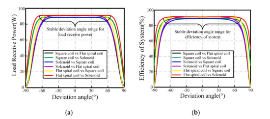
Figure 12.
Simulation results under different coil types. (a) Load receive power vs. deviation angle. (b) Efficiency of system vs. deviation angle.
4. Experimental Verification and Analysis
4.1. Experimental System
An experimental platform of WPT via CMR was built based on simulations, as shown in Figure 13. The signal generator was connected to the RF power amplifier as the high-frequency power supply for the experimental system. The coupling coil was connected in parallel with the vacuum adjustable capacitor. The coupling coil maintains resonance at the operating frequency by adjusting the vacuum capacitor. The system load used an attenuator, with a resistance of 50 Ω. The load receive power was measured by a BIRD high-precision power meter. The coupling coils were fixed on a customized bracket, and the deviation angle of the coil can be arbitrarily changed. The coil parameters were consistent with those in simulations, and the operating frequency of the system was 6.78 MHz.
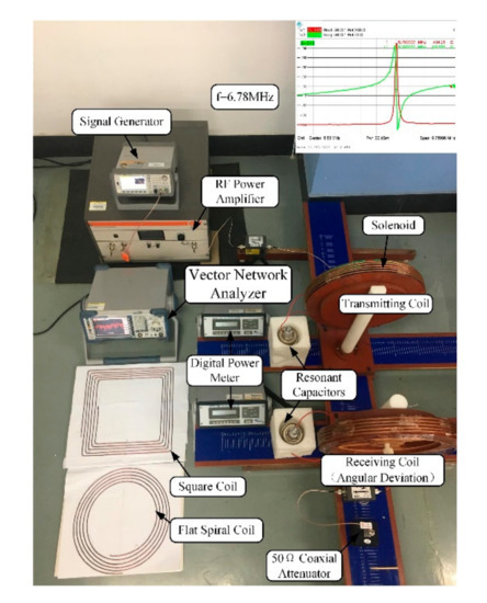
Figure 13.
Experimental setup and coils.
4.2. Analysis of Symmetrical System
On the experimental platform, the transmitting and receiving coils used symmetrical flat spiral coils. The coil radius was 200 mm, the number of turns was 5, and the gap between turns was 10 mm. A vector network analyzer (R&S 9 kHz–6 GHz) was used to determine the self-resonant frequency of coils. The resonant frequency was maintained at 6.78 MHz by adjusting the vacuum capacitor, which was connected in parallel with the coil. Then, the distance between the transmitting and receiving coils was changed to observe the load receive power. Experimental results show that the critical coupling distance between coupling coils was 287 mm. The distances between the receiving and transmitting coils were fixed at 215 mm, 287 mm, and 373 mm, respectively, and the deviation angle of the receiving coil was changed and measured every 10°. The distance between coupled coils was represented by D, and the load receive power and system efficiency at different distances are shown in Figure 14.
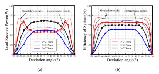
Figure 14.
Experimental results at different distances. (a) Load receive power vs. deviation angle. (b) System efficiency vs. deviation angle.
The dashed line in Figure 14 represents the simulation result, which is slightly higher than the experimental result due to losses brought by various measuring instruments in the experiment. When the distance between coupling coils is 215 mm and the deviation angle is between 30° and 60°, the load receive power shows an upward trend. Then, it drops to zero when the coupling coils are perpendicular to each other. The system efficiency remains basically unchanged within a range of deviation angle and then decreases. The closer the coupling coils, the higher the system efficiency and the larger the range of the deviation angle that keeps the system efficiency basically unchanged. Experimental results were consistent with the simulation results, which verified the theoretical analysis.
4.3. Analysis of Asymmetrical System
First, experiments were conducted on an asymmetric system with different transmitting and receiving coils, in which flat spiral coils were used and the radius of the transmitting coil was fixed at 200 mm. The distance between coupling coils was 287 mm. The radius of the receiving coil was changed, and five different radius ratios were set. The change in system efficiency with the angle deviation after adjusting the resonance frequency is shown in Figure 15a. Then, experiments were conducted on an asymmetric system with different combinations of coil types, and results show that the critical coupling distances of the three combinations were 307 (square coil vs. flat spiral coil), 294 (flat spiral coil vs. solenoid), and 332 (solenoid vs. square coil), respectively. The system efficiencies at different deviation angles are shown in Figure 15b. Similarly, the dashed line in Figure 14 represents the simulation result.
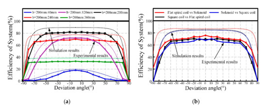
Figure 15.
(a) System efficiency vs. deviation angle at different radius ratios. (b) System efficiency vs. deviation angle under different combinations of coil types.
From the experimental results, it can be seen that the system efficiency will remain constant within a certain range of deviation angle at different radius ratios. The larger the radius of the receiving coil, the larger the range of the deviation angle that keeps the system efficiency basically unchanged. When the radius ratio was 1:1.8, the range was the largest. At the same time, the range of deviation angle that can stabilize the system efficiency was wider when the shape of the transmitting coil was flat spiral and that of the receiving coil was solenoid.
5. Conclusions
- In a symmetrical WPT system via CMR, the load receive power increases first and then decreases with the growing deviation angle when the receiving coil is within the over-coupling distance from the transmitting coil. This shows that the angular offset can compensate to a certain extent for the power loss caused by the frequency splitting phenomenon. The system efficiency can remain non-directional within a certain range of deviation angle. The tolerance of the maximum deviation angle is about 70°. The closer the distance between coupling coils, the longer the range of non-directionality.
- In an asymmetrical WPT system via CMR, the system efficiency can remain non-directional within a range of deviation angle. The larger the radius of the receiving coil, the larger the range of non-directionality, and at the same time, the transmission efficiency of the system is reduced. When the shape of the transmitting coil is flat spiral and that of the receiving coil is solenoid, the non-directional range of the system is larger than other combinations. The tolerance of the maximum deviation angle is about 70°.
The conclusions above provide a reference for the design of the coupling mechanism in omnidirectional energy transfer system, and provide a directional standard for improving the robustness of the transmission system.
Author Contributions
Conceptualization, Y.Z.; Formal analysis, Z.L.; Funding acquisition, Y.L.; Resources, Q.Y.; Validation, X.N.; Writing—review & editing, J.L. All authors have read and agreed to the published version of the manuscript.
Funding
This research was funded by the National Natural Science Foundation of China under Grant 51877151, Grant 51577133, Grant 51807138, and in part by the Program for Innovative Research Team in University of Tianjin under Grant TD13-5040.
Conflicts of Interest
The authors declare no conflict of interest.
References
- Hui, S.Y.R.; Zhong, W.; Lee, C.K. A Critical Review of Recent Progress in Mid-Range Wireless Power Transfer. IEEE Trans. Power Electron. 2013, 29, 4500–4511. [Google Scholar] [CrossRef]
- Bi, Z.; Kan, T.; Mi, C.C.; Zhang, Y.; Zhao, Z.; Keoleian, G.A. A review of wireless power transfer for electric vehicles: Prospects to enhance sustainable mobility. Appl. Energy 2016, 179, 413–425. [Google Scholar] [CrossRef]
- Jiang, H.; Zhang, J.; Lan, D.; Chao, K.K.; Liou, S.; Shahnasser, H.; Fechter, R.; Hirose, S.; Harrison, M.; Roy, S. A Low-Frequency Versatile Wireless Power Transfer Technology for Biomedical Implants. IEEE Trans. Biomed. Circuits Syst. 2012, 7, 526–535. [Google Scholar] [CrossRef] [PubMed]
- Kim, H.-J.; Hirayama, H.; Kim, S.; Han, K.J.; Zhang, R.; Choi, J.-W. Review of Near-Field Wireless Power and Communication for Biomedical Applications. IEEE Access 2017, 5, 21264–21285. [Google Scholar] [CrossRef]
- Wang, C.-S.; Stielau, O.; Covic, G. Design Considerations for a Contactless Electric Vehicle Battery Charger. IEEE Trans. Ind. Electron. 2005, 52, 1308–1314. [Google Scholar] [CrossRef]
- Keeling, N.A.; Covic, G.A.; Boys, J.T. A Unity-Power-Factor IPT Pickup for High-Power Applications. IEEE Trans. Ind. Electron. 2009, 57, 744–751. [Google Scholar] [CrossRef]
- Kurs, A.; Karalis, A.; Moffatt, R.; Joannopoulos, J.D.; Fisher, P.; Soljačic, M. Wireless Power Transfer via Strongly Coupled Magnetic Resonances. Science 2007, 317, 83–86. [Google Scholar] [CrossRef] [PubMed]
- Karalis, A.; Joannopoulos, J.D.; Soljacicb, M. Efficient wireless non-radiative mid-range energy transfer. Ann. Phys. 2008, 323, 34–48. [Google Scholar] [CrossRef]
- Mohamed, A.A.S.; Marim, A.A.; Mohammed, O.A. Magnetic design considerations of bidirectional inductive wireless power transfer system for EV applications. IEEE Trans. Magn. 2017, 53, 1–5. [Google Scholar] [CrossRef]
- Suh, Y.-H.; Chang, K. A high-efficiency dual-frequency rectenna for 2.45- and 5.8-GHz wireless power transmission. IEEE Trans. Microw. Theory Tech. 2002, 50, 1784–1789. [Google Scholar] [CrossRef]
- Casanova, J.J.; Low, Z.N.; Lin, J.; Tseng, R. Transmitting coil achieving uniform magnetic field distribution for planar wireless power transfer system. In Proceedings of the 2009 IEEE Radio and Wireless Symposium, San Diego, CA, USA, 18–22 January 2009; pp. 530–533. [Google Scholar]
- Lee, E.S.; Choi, B.G.; Choi, J.S.; Nguyen, D.T.; Rim, C.T. Wide-Range Adaptive IPT Using Dipole Coils With a Reflector by Variable Switched Capacitance. IEEE Trans. Power Electron. 2016, 32, 8054–8070. [Google Scholar] [CrossRef]
- Mai, R.; Chen, Y.; Zhang, Y.; Yang, N.; Cao, G.; He, Z. Optimization of the Passive Components for an S-LCC Topology-Based WPT System for Charging Massive Electric Bicycles. IEEE Trans. Power Electron 2017, 65, 5497–5508. [Google Scholar] [CrossRef]
- Wang, W.; Huang, X.; Pan, S.; Guo, J. Moving impedance matching analysis for three-coil wireless power transfer system in mid-range. In Proceedings of the 2016 IEEE 5th Asia-Pacific Conference on Antennas and Propagation (APCAP), Kaohsiung, Taiwan, 26–29 July 2016; pp. 429–430. [Google Scholar]
- Lee, G.; Waters, B.H.; Shin, Y.G.; Smith, J.R.; Park, W.S. A Reconfigurable Resonant Coil for Range Adaptation Wireless Power Transfer. IEEE Trans. Microw. Theory Tech. 2016, 64, 1–9. [Google Scholar] [CrossRef]
- Nguyen, V.T.; Kang, S.H.; Choi, J.H.; Jung, C.W. Magnetic resonance wireless power transfer using three-coil system with single planar receiver for laptop applications. IEEE Trans. Consum. Electron. 2015, 61, 160–166. [Google Scholar] [CrossRef]
- Zhang, X.; Gao, L.; Wang, C.; Wang, Z.; Fan, X. Design and Simulation Analysis on the Transmitter/Receiver of MCR-WPT. In Proceedings of the 2018 11th International Symposium on Computational Intelligence and Design (ISCID), Hangzhou, China, 8–9 December 2018; pp. 157–160. [Google Scholar] [CrossRef]
- Kim, H.; Hwang, K.; Park, J.; Kim, N.; Ahn, S. Design of single-sided AC magnetic field generating coil for wireless power transfer. In Proceedings of the 2017 IEEE Wireless Power Transfer Conference (WPTC), Taipei, Taiwan, 10–12 May 2017; pp. 1–3. [Google Scholar]
- Tran, D.H.; Vu, V.-B.; Pham, V.-L. Design of a High-Efficiency Wireless Power Transfer System with Intermediate Coils for the On-Board Chargers of Electric Vehicles. IEEE Trans. Power Electron. 2017, 33, 175–187. [Google Scholar] [CrossRef]
- Abdolali, A.; Jafari, A.M. Flexible Control of Magnetic Fields by Shaped-Optimized Three-Dimensional Coil Arrays. IEEE Magn. Lett. 2019, 10, 1–5. [Google Scholar] [CrossRef]
- Feng, J.; Li, Q.; Lee, F.C. Omnidirecitional wireless power transfer for portable devices. In Proceedings of the 2017 IEEE Applied Power Electronics Conference and Exposition (APEC), Tampa, FL, USA, 26–30 March 2017; pp. 1675–1681. [Google Scholar]
- Houran, M.A.; Yang, X.; Chen, W. Free Angular-Positioning Wireless Power Transfer Using a Spherical Joint. Energies 2018, 11, 3488. [Google Scholar] [CrossRef]
- Agbinya, J.I.; Mohamed, N.F.A. Design and study of multi-dimensional wireless power transfer transmission systems and architectures. Int. J. Electr. Power Energy Syst. 2014, 63, 1047–1056. [Google Scholar] [CrossRef]
- Lee, G.; Waters, B.H.; Shi, C.; Park, W.S.; Smith, J.R. Design considerations for asymmetric magnetically coupled resonators used in wireless power transfer transfer applications. In Proceedings of the 2013 IEEE Radio and Wireless Symposium, Austin, TX, USA, 20–23 January 2013; pp. 328–330. [Google Scholar]
- Babic, S.; Akyel, C. Calculating Mutual Inductance Between Circular Coils With Inclined Axes in Air. IEEE Trans. Magn. 2008, 44, 1743–1750. [Google Scholar] [CrossRef]
- Dang, Z.; Abu Qahouq, J.A. Modeling and investigation of magnetic resonance coupled wireless power transfer system with lateral misalignment. In Proceedings of the 2014 IEEE Applied Power Electronics Conference and Exposition—APEC 2014, Fort Worth, TX, USA, 16–20 March 2014; pp. 1317–1322. [Google Scholar]
- Wang, J.; Li, J.; Ho, S.L.; Fu, W.; Li, Y.; Yu, H.; Sun, M. Lateral and Angular Misalignments Analysis of a New PCB Circular Spiral Resonant Wireless Charger. IEEE Trans. Magn. 2012, 48, 4522–4525. [Google Scholar] [CrossRef]
- Kim, S.-M.; Cho, I.-K.; Moon, J.-I.; Yoon, J.-H.; Byun, W.-J.; Choi, J.-I. 1.9MHz wireless power transmission system using coupled magnetic resonance. In Proceedings of the 2012 19th International Conference on Microwaves, Radar & Wireless Communications, Warsaw, Poland, 21–23 May 2012; Volume 2, pp. 519–522. [Google Scholar]


Publisher’s Note: MDPI stays neutral with regard to jurisdictional claims in published maps and institutional affiliations. |
© 2020 by the authors. Licensee MDPI, Basel, Switzerland. This article is an open access article distributed under the terms and conditions of the Creative Commons Attribution (CC BY) license (http://creativecommons.org/licenses/by/4.0/).