Abstract
In this paper, passivity-based control (PBC) of a Luo converter-fed DC motor is implemented and presented. In PBC, both exact tracking error dynamics passive output feedback control (ETEDPOF) and energy shaping and damping injection methods do not require a speed sensor. As ETEDPOF does not depend upon state computation, it is preferred in the proposed work for the speed control of a DC motor under no-load and loaded conditions. Under loaded conditions, the online algebraic approach in sensorless mode (SAA) is used for estimating different load torques applied on the DC motor such as: constant, frictional, fan-type, propeller-type and unknown load torques. Performance of SAA is tested with the reduced order observer in sensorless mode (SROO) approach and analyzed, and the results are presented to validate the low-cost implementation of PBC for a DC drive without a speed and torque sensor.
1. Introduction
Electrical motors are the workforce in industrial applications. They are generally needed to work under variable speeds and for unknown load torque scenarios. DC and AC motors are used for this purpose. Though an induction motor is robust, cost-effective and cheaper in maintenance, a DC motor is preferred due to its good dynamic response in comparison to an AC motor, simple controlling methods and wide speed control. Due to these reasons, the DC motor is extensively used in rolling mills, paper machines and unwinding and rewinding machines.
The feedback regulation of a DC motor is achieved through the pulse width modulation (PWM) of the DC-DC converter. The typical way of controlling DC-DC converters relies on an averaged, small-signal model, facilitating the application of linear control theory [1] which yields satisfactory results in many applications. In some situations, this approach offers limited performance or may even fail. Such situations may require tight tracking of the reference voltage during sudden load variations. Passivity-based control (PBC) will alleviate this kind of problem [1]. It is based on the energy calculations in the system. If the model of any system is converted to its energy perspectives, PBC can be implemented easily. PBC is developed for achieving stabilized output trajectories based on the required reference trajectories.
In PBC, all the systems are modeled in terms of conservative forces, dissipative forces and the energy acquisition part. The control function of PBC for any system is derived in such a way that an error in the energy satisfies Lyapunov’s stability along with the dissipation matching condition.
Robustness, a stability feature of the PBC approach in various applications, confirms the selection of PBC [2,3,4,5,6,7] in the present work. Further, PBC outperforms the proportional–integral controller (PIC) in the control of the power flow [4]. Tzann-Shin Lee proved a better performance of PBC + PIC in power converter circuits.
Tofighi et al. achieved a good tracking response with PBC in comparison with PIC [5]. The authors demonstrated the robustness of PBC in a photovoltaic power management system [5]. In synchronous reluctance motor drive systems [6] and in DC drive systems, PBC outperforms PIC. From the above, it is concluded that PBC performs better than other controllers.
Due to this, PBC finds applications in microgrids [8,9], inverters [10], wind power systems [11], HVDC [12], power converter-based applications [13,14,15,16,17,18,19,20,21,22], robotics [23,24,25], MEMS [26], ball and beam dynamical systems [27] and photovoltaic systems [28].
In PBC, the exact tracking error dynamics passive output feedback (ETEDPOF) method is preferred for the present work in comparison with energy shaping and damping injection (ESDI) due to the absence of controller state computation in ETEDPOF [29]. Linares-Flores J et al. [30] implemented ETEDPOF for a DC motor under loaded conditions with two load torque estimation schemes, namely: the online algebraic approach and the reduced order observer in sensorless mode approach with a speed sensor [30]. In continuation of that, Ganesh Kumar S and Hosimin Thilagar attempted the same approaches for a DC motor without any speed sensor which is a fourth-order flat system [31]. The schemes are termed as online algebraic approach in sensorless mode (SAA) and reduced order observer approach in sensorless configuration (SROO). A system is called flat when the order of the system equals to the relative degree and the corresponding reference profiles can be generated easily. Hence, it is decided to propose the ETEDPOF technique with SAA and SROO schemes for a sixth-order partially flat system, namely: a Luo converter with dynamic load without any speed as well as torque sensor.
2. Development of Controller and Estimation of Torque with Reduced Number of Sensors
The ETEDPOF method [31] is developed from the energy managing structure of the error dynamics, which can be placed in generalized Hamiltonian form, identifying the passive output associated with this stabilization of the error dynamics. Based on these error dynamics, a simple linear, time-invariant feedback controller may be synthesized which will achieve the desired equilibrium point into a semi-globally asymptotically stable equilibrium for the closed-loop system, provided a structural dissipation matching condition would be satisfied [2].
This chapter is organized as follows: the general procedure for controller development is presented in Section 2.1. ETEDPOF and load torque schemes for the Luo converter with dynamic load are presented in Section 2.2.
2.1. General Procedure for ETEDPOF Development
The Hamiltonian of any system represents an energy function (H), and it can be written in terms of state vector “x”, which is given in Equation (1):
where M is a positive-definite and constant matrix. On taking the partial derivative of Equation (1) with respect to “x”, Equation (2) is obtained.
Generally, any averaged state model can be represented in Equation (1)
Matrix J is skew-symmetric in nature which will not affect the system stability as
xTJ(u)x = xJ(u)xT = 0
The term “bu” is the energy acquisition term. External disturbances like load torque are introduced in . R is symmetric and positive-semi-definite,
The skew symmetric matrix J(u) can be written as
The main objective of the present work is to regulate the speed of a DC motor for a given desired speed profile () under no-load and load conditions. The desired speed profile is obtained in an offline fashion using bezier polynomials. For this desired speed profile (), it is assumed that a state reference trajectory x*(t) satisfies the desired open-loop dynamics and it is given by
The matrix J(u) is skew-symmetric which is related to an average control input “u” and it satisfies the following expansion property:
where is a skew symmetric constant matrix.
Under steady-state conditions, state trajectory “x” will reach x* and control input “u” becomes u*. Now, Equation (7) is modified to
In order to implement closed-loop operation, errors in the system’s state trajectories should be identified to modify the control input. These errors in the state trajectory (e) and control input (eu) are calculated as given below:
On differentiating Equation (10) with respect to time “t”,
On adding and subtracting the required steady-state values to Equation (12), this yields
The value of obtained from Equation (9) is substituted in Equation (13), then the error dynamics will become
On using Equation (7) in Equation (14), the error dynamics of the system are modified into
where
In Equation (13), is a conservative term which will not affect the stability property of the system,
Other remaining terms exactly coincide with the tangent linearization part of the dynamics [2].
The passive output tracking error is given by
A linear time-varying average incremental passive output feedback controller is simply given by
On substituting Equation (20) in Equation (16), the error dynamics of the system will become
Now, with the skew symmetric property of J(u), is given by
Equation (23) is negative-definite if the dissipation matching condition (24) is satisfied.
In general, satisfaction of the dissipation matching condition will be in two forms and both forms are explained below:
Case I:
This indicates that the dissipation matching condition is strictly satisfied and Equation (18) will become negative-definite.
Case II:
Here, the dissipation matching condition is not strictly satisfied. For these cases, LaSalle’s theorem [4] is used to establish the global asymptotic stability of the origin of the tracking error space.
LaSalle’s theorem can be stated as follows: suppose that there exists a positive-definite function, H: Rn→R, whose derivative satisfies the inequality and if, moreover, the largest invariant set contained in the set {x: } is equal to {0}, then the system is globally asymptotically stable. Due to the bounded nature of the control input [0 & 1] in power electronic converters, the system can be semi-globally asymptotically stable.
Now, the dissipation matching condition and the average control input are given by
where “” represents the damping injection coefficient whose value can be considered of low value to avoid noise amplification.
Thus, the control input for regulating the speed of the DC motor is obtained. The control function (u) in Equation (26) clearly indicates the absence of the derivative term which makes the controller simpler.
2.2. ETEDPOF and Estimation of Torque in Sensorless Mode for the Luo Converter System
Earlier differentially flat and non-flat systems of order four were considered for sensorless load torque estimation and ETEDPOF implementation [22,31]. In this paper, a sixth-order non-flat system is proposed for analysis. One example of a non-flat sixth-order system is a Luo converter-fed DC motor. Out of many pump circuits, the fundamental Luo converter is taken for analysis. The relative degree of the Luo converter-fed DC motor is three which is less than the order of the system. This confirms the unstable internal dynamics of the Luo converter inductor current and capacitor voltage with respect to the speed. Hence, reference trajectories are developed in an indirect manner.
Figure 1 represents the low-cost load torque estimation of the Luo converter with dynamic load using the feedback signal’s armature voltage (v2) and armature current (iam), whereas ETEDPOF can be implemented with inductor currents (i1 and i2) capacitor voltage (v1).
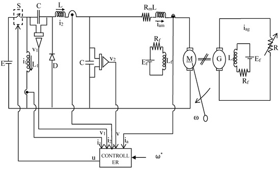
Figure 1.
Non-flat Luo converter with dynamic load for low-cost passivity-based control (PBC) implementation.
With the available wide variety of pump circuits, the fundamental positive output Luo converter is taken for the present work. Using Kirchhoff’s laws and Newton’s laws, a linear averaged model for a Luo converter-fed DC motor can be derived. Due to the selection of the armature control method for speed control, field circuit equations are omitted. The derived linear averaged model is given by
where:
- -
- —Inductor () current (Ampere)
- -
- —Inductor () current (Ampere)
- -
- —Capacitor () voltage (Volt)
- -
- —Capacitor () voltage (Volt)
- -
- —Motor armature current (Ampere)
- -
- ω—Angular velocity (rad/seconds)
- -
- k—Torque constant (N. m/A)
- -
- Rm—Motor armature resistance (Ohm)
- -
- Lm—Motor armature inductance (Henry)
- -
- u—Control input
- -
- N—Speed (RPM)
- -
- E—Supply voltage (Volt)
- -
- Rfm—Motor field resistance (Ohm)
- -
- Lfm—Motor field inductance (Henry)
- -
- J—Moment of inertia (Kgm2)
Using matrix notation, the state vector is shown in Equation (33)
and the matrices are given from Equation (34) to Equation (37):
Matrix J is skew-symmetric in nature. R is symmetric and positive-semi-definite,
The skew symmetric matrix J(u) can be written as
where J0 and J1 are skew symmetric constant matrices which are given in Equations (40) and (41):
The total stored energy of the system is given as
where the matrix “M” is given by
which is positive-definite and constant. Thus, the average model of the Luo converter-fed DC motor is modified. The ETEDPOF control law can be derived by substituting the necessary matrices in Equation (26) and it is given by
In the present case, the dissipation matching condition is not strictly satisfied, and the final dissipation matching matrix is given by
Since is positive-semi-definite whenever t , the control law (44) makes the origin of the error space an asymptotically stable equilibrium point by virtue of LaSalle’s theorem.
2.2.1. Stability Proof
The error dynamics in the Luo converter and the first derivative of energy can be written as
and they are calculated as
where and . This indicates that LaSalle’s theorem is established, and the origin of the error space is globally asymptotically stable. Therefore, due to the bounded nature of the control input between 0 and 1, the origin of the error space is semi-globally asymptotically stable.
In terms of converter inductor currents i1 and i2 and voltage v1, the feedback control law (44) governs the speed of the Luo converter-fed DC motor to stabilize the reference trajectory . The value of . The control law (44) indicates the necessity of reference trajectories in terms of speed, and the load torque estimated will be presented in the next section.
2.2.2. Generation of Reference Trajectories
In continuation of the derived feedback law (44), it is necessary to generate voltage and current references for the Luo converter circuit, i.e., v1*(t), i2*(t) and i1*(t). In order to realize a smooth starter, reference trajectories in terms of speed and load torque have to be calculated. Reference trajectories can be calculated easily for the differentially flat system.
As the relative degree of the system is three, the Luo converter-fed DC motor is a non-flat system. Relative degree can be calculated by differentiating the output variable continuously till the control input is reached [31]. In the Luo converter with dynamic load, the control input is reached in the third step and hence the relative degree is three. Thus, the relative degree is not equal to the system of order six. Due to this reason, the system is considered as a non-flat system.
As the system is non-flat, reference trajectories for v1*(t), u* and i1*(t) are generated from the fundamental working principle of the Luo converter which is explained below:
Figure 2 and Figure 3 depict the operation of the Luo converter in “on” and “off” conditions. Due to the high-frequency operation, variations in the inductor currents i1 and i2 are negligible. Inductor current profile i1 is obtained by equating the amount of charge in the capacitor when the switch is “on” (Figure 2) and “off” (Figure 3). The charge balance equation is presented in Equation (33).
where “T” represents the time duration for one switching. From (34), the reference profile for i1 is given by
(Charge during switch off conditions)Q+ = Q−(Charge during switch on conditions)
(1u)*T*i1 = u*T*i2
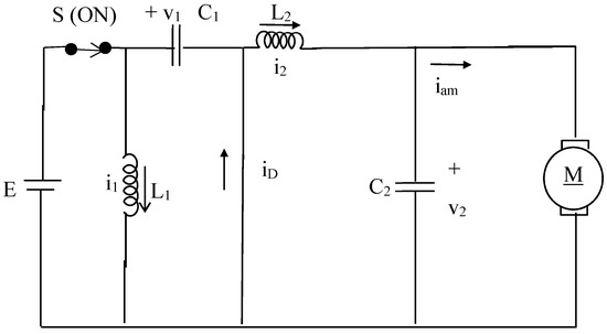
Figure 2.
Converter status when the switch is on (field circuit of motor is omitted).
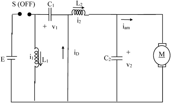
Figure 3.
Converter status when the switch is off (motor field circuit is omitted).
As capacitor C2 performs as a low-pass filter, the load current iload = i2. Hence,
Source current is given by isource = i1 + i2 when the switch is on and it is zero when the switch is off. Thus, the average source current (isourcea) is presented in Equation (53):
Hence, the load current is given by
and the output voltage is
when the switch is on, inductor current increases and is supplied by E. Further, current decreases when the switch is off. Therefore,
uTE = (1 − u)Tv1
Hence, variations in capacitor voltages are equal, i.e.,
From this, it can be concluded that, for the desired voltage profile , will follow . Hence, the control input, inductor current i1 and other profiles are given by
For the generation of reference trajectories of the Luo converter voltage and inductor current , differential parameterizations in terms of the desired angular velocity and the estimated load torque are performed and the equations are given in (61) and (62). In order to define the trajectory, the Bezier polynomial of the fifth order is used.
Thus, the trajectories of the desired speed profile and its corresponding voltage and current profiles have been achieved in this section. These reference values are used for sensorless operation under no-load and loading conditions of a Luo converter-fed DC motor. In order to update the value of load torque under closed-loop operation, estimation of load torque is essential, and the method is discussed in the next section.
Load torque estimation is essential in the speed control of DC motors under loaded conditions. The space constraint restricts the use of a torque sensor and thus the observer scheme and algebraic approach [30].
2.2.3. Reduced Order Observer in Sensorless Configuration for Estimating Load Torque
Linares-Flores et al. [30] proposed a reduced order observer (ROO) approach for the load torque estimation of a DC motor. The load torque is obtained from the mechanical model of the DC motor using the measured speed and armature current as
Setting ,.
Clearly, for , the observation error , where , exponentially converges to zero. This estimated torque is used in the ETEDPOF implementation along with other feedback signals received from the power converter. To restrict the use of the speed sensor, ROO is implemented without a speed sensor and the scheme is known as the reduced order observer approach in sensorless mode (SROO).
SROO-based estimation of load torque is found by replacing speed “ω” by Equation (65) in Equation (64). The resultant expression is shown in Equation (66).
Based on the value of , the convergence rate will vary. Moreover, for a high value of , estimation will become unstable. To avoid this problem, the algebraic approach is employed [30].
2.2.4. Online Algebraic Approach in Sensorless Mode (SAA)
Online algebraic approaches of estimating load torque with a speed sensor [2] and in sensorless mode are given in (67) and (70). As the estimated torque is getting updated for every o.o3 s (), estimation becomes quick.
Load torque values are decided based on the constraints mentioned below:
With
where —reset time.
3. Results
To validate the features, an ETEDPOF controller is implemented for the Luo converter-fed DC motor under no-load condition and loaded conditions.
3.1. Flow Diagram
Figure 4 represents the flow diagram for the implementation of ETEDPOF in the Luo converter. Further, Figure 4 indicates the path for obtaining the control input for speed regulation. Two types of load torque estimation methods, namely SAA and SROO, are applied and the performances are compared. From the desired speed profile and estimated load torque, the desired armature voltage v2* and desired inductor current i2* are obtained using Equations (61) and (62), respectively. With the help of v2*, the desired control function u* is obtained using Equation (59). The desired capacitor voltage v1* is obtained using Equation (63). i2*and u* are used for obtaining i1* by using Equation (60). From the feedback signals v1, i1 and i2, the control input is calculated using Equation (44) along with the knowledge of i1*, i2*, v1* and u*. This control input is given as input to the switch of the Luo converter.
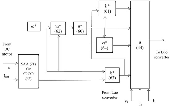
Figure 4.
Flow diagram for the ETEDPOF implementation.
Sensorless load torque estimation with the ETEDPOF implementation is completed for 12 s in the hardware and simulation. Simulation is performed using MATLAB SIMULINK.
3.2. Experimental Setup
The experimental setup for the ETEDPOF implementation under load and no-load conditions is shown in Figure 5. The setup includes a Luo converter, a DC motor coupled with a DC motor which will act as a generator, a controller and appropriate sensors with signal conditioning circuits. Speed can be measured using a phototransistor (MOC 7811) and encoder disc. The load torque in the DC motor can be modified by varying the load in the DC generator.
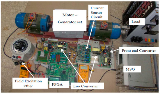
Figure 5.
Hardware setup for the Luo converter-fed DC motor.
The Luo converter and controller are used for controlling the DC motor speed under the armature control method. The specifications for the system of interest and the base values are given in Table 1. Hardware waveforms are stored in comma separated value (CSV) format and then these values are exported to MATLAB along with the simulated values for the comparison of both hardware and simulation results.

Table 1.
Specifications for ETEDPOF control of a Luo converter with dynamic load.
The total operation is divided into two broad categories, namely servo control and regulatory control operations, based on the free acceleration, change of speed reference and step change in load torque conditions.
In servo control mode, speed control of the Luo converter-fed DC motor is performed under free acceleration and at different constant load torques of value 0.5, 1.0 and 0.25 p. u. (Figure 6). In regulatory control mode, speed control is achieved along with two load torque estimation schemes, namely the algebraic approach in sensorless mode (SAA) and the reduced order observer in sensorless mode approach (SROO), and both schemes are compared without any speed sensor. In SROO, based on the value of the tuning constant, it is classified into SROO1 and SROO2 for which the value is equal to 5 and 10, respectively.
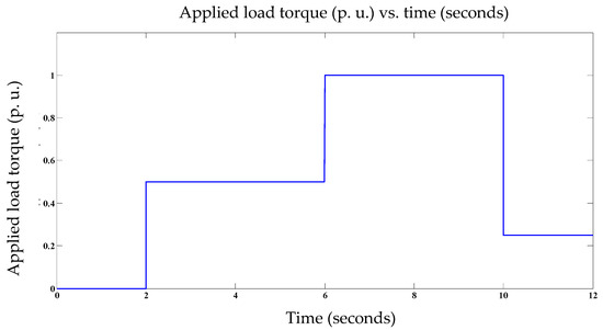
Figure 6.
Applied load torque.
3.3. Discussion
Simulation and hardware results are shown from Figure 6, Figure 7, Figure 8, Figure 9, Figure 10 and Figure 11. In the simulation, ideal components are used. Hence, the simulation performance is slightly better than hardware implementation which is clearly exhibited in Figure 6, Figure 7, Figure 8, Figure 9, Figure 10 and Figure 11. As v1 = v2 and iam = i2, inductor current and armature voltage waveforms alone are presented. Simulation and hardware results are explained below.
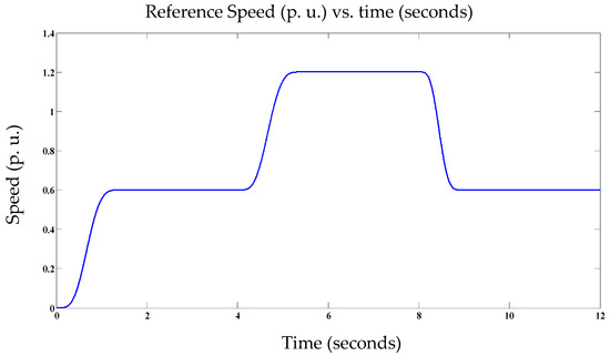
Figure 7.
Speed reference profile.
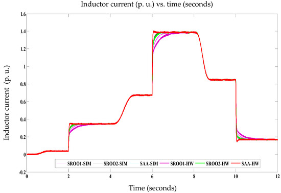
Figure 8.
Inductor current of the Luo converter.
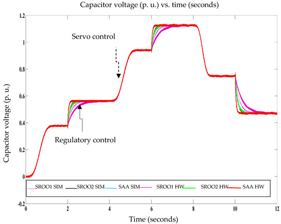
Figure 9.
Armature voltage of the Luo converter-fed DC motor.
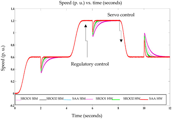
Figure 10.
Measured speed of the DC motor fed from the Luo converter.
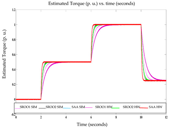
Figure 11.
Estimated torque.
Inductor current variations of the Luo converter for the given speed reference (Figure 6) and load torque applied (Figure 7) are shown in Figure 8. These variations are obtained for regulatory and servo control operations. Under regulatory control operations, SAA settles the current faster when compared with SROO. This is due to the fast estimation of load torque using SAA.
Under regulatory control operations, SAA and SROO methods are implemented to modify the reference profiles for ETEDPOF control. Due to the fast estimation nature of SAA, armature voltage settles faster than in the case of SAA when compared with SROO. As the armature voltage is equal to the capacitor voltage (v1), the armature voltage alone is presented in Figure 9.
Speed variation under servo and regulatory modes is shown in Figure 10. During starting, the speed is varied smoothly using ETEDPOF. Under loading conditions, the speed is regulated using ETEDPOF with load torque estimation.
Table 2 compares the performances of SAA and SROO in terms of speed settling time. From the above analysis and Table 2, it can be concluded that SAA performs better than SROO with less overshoot/undershoot in speed responses. Thus, the speed responses for the DC motor with ETEDPOF, SAA and SROO are analyzed.
Table 2.
Comparison between SAA and SROO: constant load torque/Luo converter with dynamic load.
Figure 11 shows the estimated torque for the DC motor using the SAA and SROO methods; both methods are tested in the simulation and hardware setup for the step change in load torque values of 0.50, 1.00 and 0.25 p. u.
Comparison between SAA and SROO estimation times are tabulated in Table 2. From the table, it can be concluded that the performance of SAA is better than SROO for all load conditions with a lower integral square error (ISE) (Figure 12).
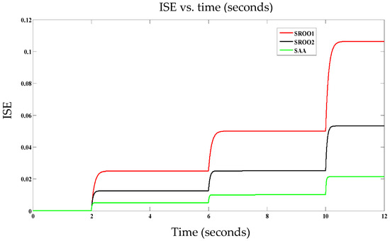
Figure 12.
Integral square error (ISE) vs. time—Luo converter-fed DC motor.
Hence, it can be concluded that SAA estimates the unknown load torque quickly when compared with SROO with the lowest integral square error (ISE), as shown in Figure 12.
3.4. Estimation of Different Load Torque Profiles
The following time-varying load torques are used for studying the capability of SAA with the speed reference, as shown in Figure 13:
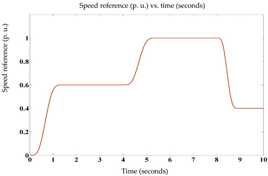
Figure 13.
Speed reference profile: Load torque proportional to speed TL α ω.
- a.
- Load torque proportional to speed (Figure 14).
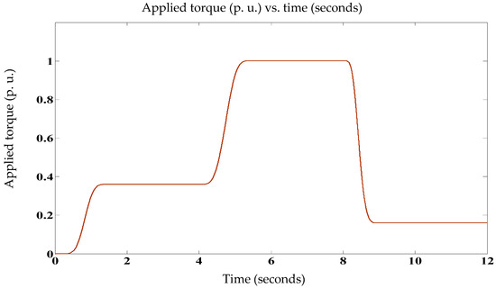 Figure 14. Applied torque: TL α ω2.
 - b.
- Load torque proportional to square of the speed (Figure 15).
 Figure 15. Applied torque: TL α ω3.
 - c.
- Load torque proportional to cube of the speed (Figure 16).
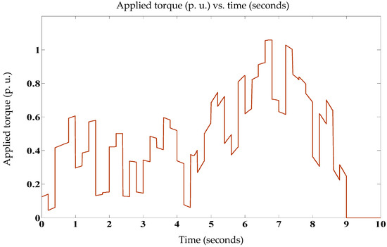 Figure 16. Applied load torque.
 - d.
- Unpredictable load torque (Figure 17).
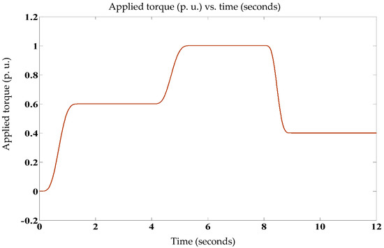 Figure 17. Torque reference: TL α ω.
These case studies are used to test the ability of SAA along with the assumption of a bounded value in load torque. MATLAB Simulink is used for studying the robustness of SAA. In the Luo converter, as capacitor voltages are equal, the armature voltage alone is considered. In addition to this, the armature current is equal to the inductor current (i2) and hence the armature current alone is considered here. Specifications for the system of interest are taken from Table 1. From the simulation results shown from Figure 18, Figure 19, Figure 20, Figure 21, Figure 22 and Figure 23, it is confirmed that SAA outperforms SROO for all types of load torques.
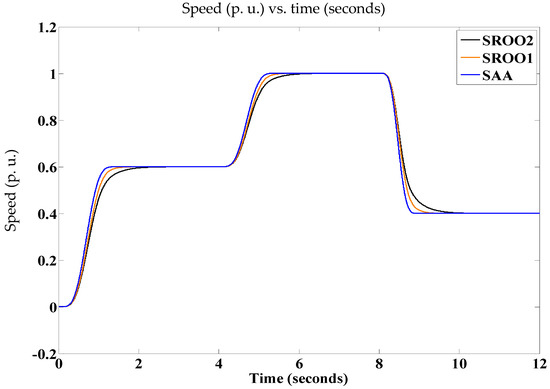
Figure 18.
Measured speed of the DC motor: TL α ω.
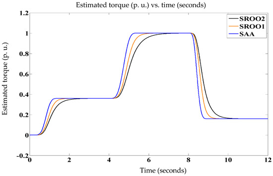
Figure 19.
Estimated torque: TL α ω2.
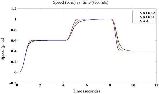
Figure 20.
Measured speed: TL α ω3.
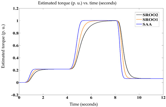
Figure 21.
Estimated torque: TL α ω3.
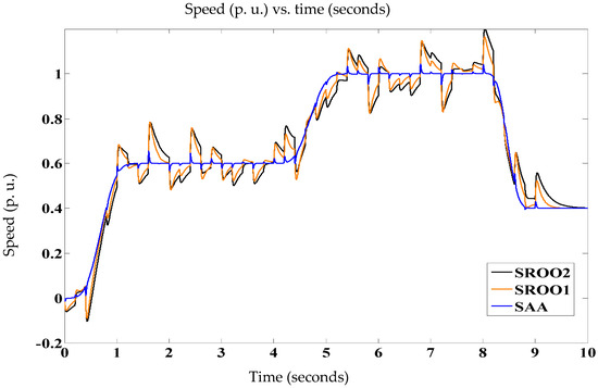
Figure 22.
Armature speed of the DC motor: unknown load torque.
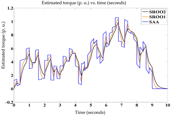
Figure 23.
Estimated torque: unknown load torque.
4. Conclusions
A methodology for sensorless speed control of a DC motor-driven system with a faster and stable trajectory tracking approach is developed. Considering the robustness, stability and high speed of trajectory tracking offered by the passivity-based control law, it has been chosen to implement the speed control of the DC motor where two methodologies of PBC, viz., ETEDPOF and ESDI, are investigated. A further two algorithms, viz., SAA and SROO, were considered for the estimation of load torque which, in turn, are used for implementing the sensorless speed control of the DC motor drive system under variable load torque conditions. All the investigations are performed on the prototype experimental setup of a DC motor drive system fed by the converter topologies, viz., a Luo converter and a sixth-order non-differentially flat system.
Here, a sixth-order non-differentially flat system Luo converter-fed DC motor is considered in which Lyapunov’s stability condition is not strictly satisfied. Therefore, LaSalle’s theorem is used for establishing asymptotic stability.
The relative degree of the Luo converter-fed DC motor is three and it is less than the order. This confirms the non-differential flatness nature of the Luo converter. So, reference profiles for the capacitor voltage (v1), control input (u) and inductor current (i1) are obtained from the fundamental working principle of the Luo converter. Using these references and the capacitor voltage (v2) and inductor current (i2) reference profiles in terms of speed and load torque, the ETEDPOF control law is implemented successfully in the Luo converter-fed DC motor tested successfully for various speed references and at different load conditions as servo and regulatory control, respectively.
Hence, from the above, it can be concluded that, irrespective of the flatness nature and order of the system, the ETEDPOF control law is developed and implemented successfully. This clearly shows the faster, stabler trajectory control with less overshoot/undershoots.
Further, a comparative study of the SAA and SROO methods confirms that SAA is capable of any type of load torque. Due to the fast estimation of load torque using SAA, the control input, armature voltage and armature currents are changing at a faster rate in comparison with SROO where the armature current and inductor current exhibit some overshoot which is due to .
Therefore, the highlighted work in this paper may be resumed as follows:
- (a)
- Development and implementation of a sensorless passivity based-control scheme, that is, ETEDPOF—SAA for the servo and regulatory control of buck/boost converter-fed DC motor drive systems with a good dynamic response.
- (b)
- Under variable load torque types, viz., constant-type, frictional-type, fan-type, propeller-type and unpredictable torque-type, a good dynamic control, that is, faster and stabler control of DC motor drive systems, is achieved.
Author Contributions
Conceptualization, methodology and writing, G.K.S.; editing and supervision, H.T.S. and M.R. All authors have read and agreed to the published version of the manuscript.
Funding
The authors thank the support of DEEE, Anna University, Chennai, India for funding through NamPET Lab Scheme and the authors thank the support of Fondecyt Regular 1191028 research project and SERC Chile.
Conflicts of Interest
The authors declare no conflict of interest.
References
- Gensior, A.; Woywode, O.; Rudolph, J.; Guldner, H. On Differential Flatness. Trajectory Planning. Observers and Stabilization for DC—DC Converters. IEEE Trans. Circuits Syst. I Regul. Pap. 2006, 53, 9–2010. [Google Scholar] [CrossRef]
- Sira-Ramirez, H.J.; Silva-Ortigoza, R. Control Design Techniques in Power Electronics Devices; Springer: London, UK, 2006. [Google Scholar]
- Rajeev, V.K.A.; Rivera, M.; Kumar, S.G. Investigation on passivity based control for electrical applications. In Proceedings of the 2017 CHILEAN Conference on Electrical, Electronics Engineering, Information and Communication Technologies (CHILECON), Pucon, Chile, 18–20 October 2017; pp. 1–6. [Google Scholar]
- Lee, T.S. Lagrangian modeling and passivity-based control of three-phase AC/DC voltage-source converters. IEEE Trans. Inductrial Electron. 2004, 51, 4–902. [Google Scholar] [CrossRef]
- Linares-Flores, J.; Sira-Ramirez, H.; Cuevas-Lopez, E.F.; Contreras-Ordaz, M.A. Sensorless passivity based control of a DC motor via a solar powered sepic converter-full bridge combination. J. Power Electron. 2011, 11, 743–750. [Google Scholar] [CrossRef]
- Tofighi, A.; Kalantar, M. Power management of PV/battery hybrid power source via passivity-based control. Renew. Energy 2011, 36, 2440–2450. [Google Scholar] [CrossRef]
- Wei MYLiu, T.H.; Lin, C.K. Design and implementation of a passivity-based controller for sensorless synchronous reluctance motor drive systems. IET Electric Power Appl. 2011, 5, 335–349. [Google Scholar]
- Ji, F.; Xiang, J.; Li, W.; Yue, Q. A Feedback Passivation Design for DC Microgrid and Its DC/DC Converters. Energies 2017, 10, 14. [Google Scholar] [CrossRef]
- Hou, R.; Song, H.; Nguyen, T.; Qu, Y.; Kim, H. Robustness Improvement of Superconducting Magnetic Energy Storage System in Microgrids Using an Energy Shaping Passivity-Based Control Strategy. Energies 2017, 10, 671. [Google Scholar] [CrossRef]
- Li, T.; Cheng, Q.; Sun, W.; Chen, L. Grid-Connected Control Strategy of Five-level Inverter Based on Passive E-L Model. Energies 2017, 10, 1657. [Google Scholar] [CrossRef]
- Kim, S. Passivity-Based Robust Output Voltage Tracking Control of DC/DC Boost Converter for Wind Power Systems. Energies 2018, 11, 1469. [Google Scholar] [CrossRef]
- Liu, W.; Zheng, T.; Liu, Z.; Fan, Z.; Kang, Y.; Wang, D.; Zhang, M.; Miao, S. Active and Reactive Power Compensation Control Strategy for VSC-HVDC Systems under Unbalanced Grid Conditions. Energies 2018, 11, 3140. [Google Scholar] [CrossRef]
- Rosa, A.; De Souza, T.; Morais, L.; Seleme, S. Adaptive and Nonlinear Control Techniques Applied to SEPIC Converter in DC-DC. PFC. CCM and DCM Modes Using HIL Simulation. Energies 2018, 11, 602. [Google Scholar] [CrossRef]
- Reveles-Miranda, M.; Sánchez-Flórez, D.; Cruz-Chan, J.; Ordoñez-López, E.; Flota-Bañuelos, M.; Pacheco-Catalán, D. The Control Scheme of the Multifunction Inverter for Power Factor Improvement. Energies 2018, 11, 1662. [Google Scholar] [CrossRef]
- Rymarski, Z.; Bernacki, K.; Dyga, Ł.; Davari, P. Passivity-Based Control Design Methodology for UPS Systems. Energies 2019, 12, 4301. [Google Scholar] [CrossRef]
- Mu, X.; Chen, G.; Wang, X.; Zhao, J.; Wu, W.; Blaabjerg, F. Multi-Frequency Single Loop Passivity-Based Control for LC-Filtered Stand-Alone Voltage Source Inverter. Energies 2019, 12, 4548. [Google Scholar] [CrossRef]
- Zhang, Z.; Gercek, C.; Renner, H.; Reinders, A.; Fickert, L. Resonance Instability of Photovoltaic E-Bike Charging Stations: Control Parameters Analysis. Modeling and Experiment. Appl. Sci. 2019, 9, 252. [Google Scholar] [CrossRef]
- Yang, W.; Meng, F.; Sun, M.; Liu, K. Passivity-Based Control Design for Magnetic Levitation System. Appl. Sci. 2020, 10, 2392. [Google Scholar] [CrossRef]
- Gil-González, W.; Martin Serra, F.; Montoya, O.; Ramírez, C.; Orozco-Henao, C. Direct Power Compensation in AC Distribution Networks with SCES Systems via PI-PBC Approach. Symmetry 2020, 12, 666. [Google Scholar] [CrossRef]
- Rymarski, Z.; Bernacki, K. Different Features of Control Systems for Single-Phase Voltage Source Inverters. Energies 2020, 13, 4100. [Google Scholar] [CrossRef]
- Travieso-Torres, J.; Vilaragut-Llanes, M.; Costa-Montiel, Á.; Duarte-Mermoud, M.; Aguila-Camacho, N.; Contreras-Jara, C.; Álvarez-Gracia, A. New Adaptive High Starting Torque Scalar Control Scheme for Induction Motors Based on Passivity. Energies 2020, 13, 1276. [Google Scholar] [CrossRef]
- Kumar, S.G.; HosiminThilagar, S.; Rivera, M. Cost effective control of a partially flat boost converter fed DC motor. In Proceedings of the 2016 IEEE International Conference on Automatica (ICA-ACCA), Curico, Chile, 19–21 October 2016; pp. 1–7. [Google Scholar]
- Zhao, W.; Song, A.; Cao, Y. An Extended Proxy-Based Sliding Mode Control of Pneumatic Muscle Actuators. Appl. Sci. 2019, 9, 1571. [Google Scholar] [CrossRef]
- Wang, Y.; Yu, H.; Yu, J.; Wu, H.; Liu, X. Trajectory Tracking of Flexible-Joint Robots Actuated by PMSM via a Novel Smooth Switching Control Strategy. Appl. Sci. 2019, 9, 4382. [Google Scholar] [CrossRef]
- Guerrero-Sánchez, M.; Hernández-González, O.; Lozano, R.; García-Beltrán, C.; Valencia-Palomo, G.; López-Estrada, F. Energy-Based Control and LMI-Based Control for a Quadrotor Transporting a Payload. Mathematics 2019, 7, 1090. [Google Scholar] [CrossRef]
- Ryalat, M.; Salim Damiri, H.; ElMoaqet, H.; AlRabadi, I. An Improved Passivity-based Control of Electrostatic MEMS Device. Micromachines 2020, 11, 688. [Google Scholar] [CrossRef] [PubMed]
- Danilo Montoya, O.; Gil-González, W.; Ramírez-Vanegas, C. Discrete-Inverse Optimal Control Applied to the Ball and Beam Dynamical System: A Passivity-Based Control Approach. Symmetry 2020, 12, 1359. [Google Scholar] [CrossRef]
- Mosavi, A.; Qasem, S.; Shokri, M.; Band, S.; Mohammadzadeh, A. Fractional-Order Fuzzy Control Approach for Photovoltaic/Battery Systems under Unknown Dynamics. Variable Irradiation and Temperature. Electronics 2020, 9, 1455. [Google Scholar] [CrossRef]
- Gensior, A.; Sira-Ramírez, H.; Rudolph, J.; Guldner, H. On some nonlinear current controllers for three-phase rectifiers. IEEE Trans. Ind. Electron. 2009, 56, 2–370. [Google Scholar] [CrossRef]
- Linares-Flores, J.; Sira-Ramírez, H.; Yescas-Mendoza, E.; Vásquez-Sanjuan, J.J. A comparison between the algebraic and the reduced Order Observer in sensorless mode approaches for on-line load torque estimation in a unit power factor rectifier-DC motor system. Asian J. Control 2012, 14, 45–57. [Google Scholar] [CrossRef]
- Ganesh Kumar, S. Hosimin thilagar. In Development of Load Torque Estimation and Passivity Based Control for DC Motor Drive Systems with Reduced Sensor Count; Emerging Issues in Science and Technology; Book Publisher International: West Bengal, India, 2020; Volume 3, Chapter 1; pp. 1–25. [Google Scholar]


Publisher’s Note: MDPI stays neutral with regard to jurisdictional claims in published maps and institutional affiliations. |
© 2020 by the authors. Licensee MDPI, Basel, Switzerland. This article is an open access article distributed under the terms and conditions of the Creative Commons Attribution (CC BY) license (http://creativecommons.org/licenses/by/4.0/).