Article

Measurement-Based Investigations of the NB-IoT Uplink Performance at Boundary Propagation Conditions

by
Kamil Staniec
1,*,
Michał Kucharzak
2,
Zbigniew Jóskiewicz
1 and
Bartłomiej Chowański
3
1
Telecommunications and Teleinformatics Department, Wrocław University of Science and Technology, 50-370 Wrocław, Poland
2
Department of Systems and Computer Networks, Wrocław University of Science and Technology, 50-370 Wrocław, Poland
3
Nokia, 54-155 Wrocław, Poland
*
Author to whom correspondence should be addressed.
Electronics 2020, 9(11), 1947; https://doi.org/10.3390/electronics9111947
Submission received: 23 October 2020 / Revised: 14 November 2020 / Accepted: 16 November 2020 / Published: 18 November 2020
(This article belongs to the Section Microwave and Wireless Communications)

Abstract

:
This paper presents experimental results of investigations on narrowband Internet of Things (NB-IoT) uplink channel performance under extreme pathloss conditions, approaching the boundary maximum coupling loss (MCL) defined for cellular IoT systems. The system performance was systematically tested against several modulation coding schemes (MCSs) and a set of repetition numbers (Nrep) in electromagnetically isolated facilities, guaranteeing proper environment separation from external factors that usually affect measurements in less controlled setups. Some of the major takeaways include the following observations. Firstly, every increase in the number of repetitions by a factor of four caused the performance to improve by about 3 dB. Secondly, the switchover between extreme MCSs (i.e., MCS0 and MCS10) caused the performance to shift by about 6 dB. Thirdly, chipsets from different vendors performed similarly at small values of Nrep, but tended to diverge for larger numbers of repetitions. These findings may serve as benchmark figures for other theoretical and simulation-based studies by demonstrating performance in response to Nrep and MCSs for a vast scope of their values. Future investigations will concern the impact of multipath channels, typical in real-life deployment scenarios.

1. Introduction

1.1. The Internet of Things Position in the 5G Era

For the approaching fifth cellular generation, five main application categories have been initially identified, embracing 74 different Third Generation Partnership Project (3GPP) use cases [1]. Two categories out of five may be classified as belonging to applications characteristic of the Internet of Things (IoT) systems, intended for massive and critical communication, and they are as follows:
  • Massive machine-type communications (mMTC) [2,3] are dedicated to a large number of devices, typical for latency-tolerant, low-throughput traffic scenarios, such as with intelligent buildings (smart metering or automation), smart appliances, peripherals and wearables, and e-health. Recommendable frequency bands for mMTC are those below 1 GHz due to relatively low pathloss, resulting in considerable coverage, which is by far one of the most crucial requirements in this application group, besides the energy-saving operation and remarkable sensitivity. The large number mentioned earlier is estimated to be between 20 (by Business Insider, 2017) and 200 (IDC, Intel) billion devices by the year 2020;
  • Ultra-reliable low latency communications (URLLC) [4] feature low losses of information, very high responsivity to triggering incentives, and high availability and security, and is usually required in industrial control systems or medical applications. For better interaction with the world of things, improved radio and haptic interfaces are necessary, leading to a paradigm of the tactile Internet;
The other categories, besides the enhancement of vehicle-to-everything (V2X), include the following:
  • Enhanced mobile broadband (eMBB) [5] is a continuation of the initial Release 8 long-term evolution (LTE) development, aimed at achieving ultra-high capacities (on the order of several Gb/s in the radio interface), rendering services to densely populated users, handling the traffic of high throughput dynamics, and providing convergence between stationary and mobile services. Peak capacities are expected to be available in extremely small capacity cells (with coverage <50 m from the base station) with the use of so-called Frequency Range 2 (or new radio (NR)) frequency ranges between 24 GHz and 100 GHz, as opposed to range cells operating in Frequency Range 1 bands (below 6 GHz), providing wider-area, lower-throughput coverage and connection setup services;
  • Network operations (NO) [6] cater to such functional requirements as elastic functionalities, creating new values, migration and internetworking, optimization, enhancements, and security.
In response to the growing demand for systems surpassing the sensitivity performance of traditional general packet radio system (GPRS) for handling sensor and meter traffic, a range of communication technologies have been spawned. These, termed as IoT systems, can be further subdivided into non-cellular low-throughput networks (LTNs) and cellular IoT (CIoT) systems (see Figure 1). The former is divided further into low-power wide-area network (LPWAN) [7,8,9] and ultra-narrowband (UNB) [10] solutions; however, both are beyond the scope of this article. On the cellular side, three systems have been proposed by the 3GPP, of which the narrowband Internet of Things (NB-IoT) is deemed to be optimal for mMTC applications, particularly by satisfying the following requirements set for the CIoT in [11,12]:
  • Improve indoor coverage (e.g., in an apartment basement, or on indoor equipment that may be close to the ground floor), extending it by 20 dB when compared with commercially available legacy GPRS (non-EGPRS) devices, yielding a maximum coupling loss (MCL) of 164 dB;
  • Support a massive number of low throughput devices (up to 40 per household, resulting in the number of households per cell as in [12]);
  • Reduce complexity and improve power efficiency, allowing up to ten years of battery life in user equipment (UE) with a battery capacity of 5 Wh, even in locations with adverse coverage conditions, where up to a 20 dB coverage extension over a legacy GPRS might be needed;
  • Have a latency tolerance of up to 10 s (but preferably not exceeding this figure).

1.2. The Article Structure

The introductory part in Section 1 aims at positioning the NB-IoT within the 5G scope and lists some major technical requirements generic to all IoT systems. Section 2 introduces readers to the current state of research on NB-IoT performance by citing other investigation efforts of a similar type found in the available literature, identifying cognitive gaps and emphasizing the unique character of the research undertaken by the authors of this article. Section 3 provides the technical overview of the NB-IoT deployment scenarios (Section 3.1), its uplink and downlink channel characteristics (Section 3.2), as well as coverage-enhancing mechanisms in view of the IoT-specific maximum coupling loss requirement (Section 3.3). Section 4 is devoted to the measurement process, in particular to the lab infrastructure and equipment involved (Section 4.1) and the test scenarios, along with the system operational settings (Section 4.2). Results are presented and discussed in detail in Section 5, separately for the narrowband physical uplink shared channel (NPUSCH) (Section 5.1) and the narrowband physical random access channel (NPRACH) (Section 5.2). The section also includes a comparative analysis of performance obtained for NB-IoT and its LPWAN and UNB counterparts (Section 5.3). Concluding remarks and plans for future research continuation by investigating NB-IoT behavior in fading channels are presented in Section 6, followed by enumerated observations of a practical nature. Appendix A provides explanation of several acronyms most often used throughout the text.

2. State-of-the-Art NB-IoT Performance Research and the Paper’s Novelty

Although lots of research on NB-IoT performance has been documented, including measurement-based investigations on the energy and power consumption of NB-IoT UEs [13], boundary pathloss conditions are most often investigated in theory and by means of simulations, due to the severe difficulty associated with obtaining stable extreme attenuations in lab facilities. Accordingly, in [14], the coverage was theoretically found to improve by 3 dB per each doubling of the number of repetitions, leading to a 172.7 dB MCL for 2048 repetitions. Valuable takeaways, closely related to the findings presented in this paper, can be found in [15], where an in-depth analysis of the signal-to-noise ratio (SNR) and the resulting throughput was performed for various multipath models, focusing on two uplink channels, the narrowband physical uplink shared channel (NPUSCH) and the narrowband physical random access channel (NPRACH), and concluding with a proposal of a modified receiver structure. Though mainly theoretical, the investigations were then validated with the use of an emulated NB-IoT Qualcomm FSM chipset-based LTE base station setup. The emphasis in [15] was placed on changing SNR values by generating a high-power noise signal, rather than by forcing NB-IoT devices to operate at extremely low received signal powers, nearing an MCL of 164 dB (as was done in the current paper). A proposal for a link adaptation scheme integrated with a proper selection mechanism of the repetitions number and the modulation coding scheme (MCS) for achieving maximized throughput and coverage is included in [16].
Measurement-based investigations found in the literature, in turn, focus on site-specific campaigns that aim at determining the NB-IoT coverage obtained at particular locations. For instance, in [17], a 20 dB coverage enhancement, with respect to LTE, was demonstrated indirectly by observing the measured received power cut-off of −130 dBm during indoor and outdoor measurements in Poland. In [18], a method for extending NB-IoT cell coverage up to 45 km (confirmed in an experiment in the West Sea of South Korea), based on adding some extra traffic delay, was proposed. The authors of [19], in turn, performed measurements in Belgium, allowing a terminal to perform automatic adaptations of MCSs and repetitions to a current link quality while measuring the throughput and the delay. The resultant sensitivity (−141 dBm) served as a confirmation of the expected MCL of 164 dB. A similar approach can be found in a plethora of other studies that either concern specific networks or refer to estimating NB-IoT applicability to specific scenarios, such as healthcare or transportation [20,21,22,23].
The novelty of this paper consists of providing real-life evidence of the performance of NB-IoT uplink channels under propagation conditions near the maximum coupling loss of 164 dB. For this purpose, the authors constructed an instrumentation setup for emulating a free-space propagation environment, in which the link attenuation could be precisely controlled. The setup was assembled in the form of combined high-quality cabling, electromagnetically isolated chambers, and high-rank attenuators. The achieved ability to control the pathloss at a precision of <1 dB enabled observation of the performance of the two uplink NB-IoT channels, namely NPRACH and NPUSCH (see Section 3.2 for details) in reaction to the application of various combinations of {MCS;Nrep}. The outcomes allow one to estimate the factual measured NB-IoT response to an MCS and Nrep, and thus they may serve as benchmark figures for validating theoretical derivations found throughout the literature. According to the authors’ best knowledge, these investigations are the first contribution performed in a systematic, thorough, and fully measurement-based manner, regarding the actual NB-IoT uplink performance. Although fadings are not included in the research, the Gaussian channel is a good approximation of the propagation conditions experienced by IoT devices (see also [16]), due to their usual deployment in stationary situations, such as on sensors, meters, and gauges.

3. The NB-IoT Channels and Coverage Enhancements

3.1. NB-IoT Design Overview

The NB-IoT, initially defined by 3GPP Release 13, was conceived within an LTE framework, employing its multiple functionalities that, on the one hand, undoubtedly determine NB-IoT characteristics and boundaries. On the other hand, the existing LTE authorized spectrum, hardware, and deployed providers’ setup may be reused for NB-IoT field implementation without any extensive modernizations, including core networks.
The NB-IoT can be deployed in three different operational modes: standalone, inband, or guardband. In standalone mode, an independent and dedicated carrier is deployed with regards to, for example, refarming the global system for mobile communications (GSM) frequencies. Inband and guardband modes require coexistence with a wideband LTE carrier, where the inband version consumes at least one physical resource block (PRB) within an LTE carrier, whereas the guardband mode carrier is placed as a new resource block, which utilizes the edge frequency (guardband) of an LTE carrier. All NB-IoT mode carriers occupy a bandwidth of one LTE PRB (i.e., 180 kHz).
Design targets of the NB-IoT are oriented to cover low-end mMTC scenarios, such as extended coverage, higher latency applications, support of a massive number of low throughput and low-cost devices, minimized power consumption, or simplified network or system architecture, with the ultimate goal of providing support for applications based on smart metering or intelligent environment monitoring. To fulfill the requirements, the NB-IoT design is addressed by a plethora of 3GPP standards and employs half-duplex operation and, initially, the frequency division duplex (FDD) technique (time division duplex (TDD) support is introduced in Release 15). Access to network services is defined by a set of documents with comprehensive specifications of the physical layer and the medium access control (MAC) protocol [24,25,26,27,28].

3.2. NB-IoT Channels

Besides basic dedicated signals, such as the narrowband reference signal (NRS), narrowband demodulation reference signal (NDMRS), narrowband primary and secondary synchronization signals (NB-PSS and NB-SSS), narrowband positioning reference signal (NPRS), or narrowband wake up signal (NWUS), the NB-IoT introduces five new physical channels. In the downlink direction, there are one broadcast and two configurable downlink channels:
  • The narrowband physical broadcast channel (NPBCH) is transmitted in the first subframe and contains the NB-IoT master information block (MIB-NB);
  • The narrowband physical downlink control channel (NPDCCH) carries mainly paging indications, system information updates, and scheduling assignments with granted modulation schemes;
  • The narrowband physical downlink shared channel (NPDSCH) contains data, paging messages, system information messages, and the random access response (RAR).
In the uplink direction, there are two defined configurable channels:
  • The narrowband physical random access channel (NPRACH) enables the random access procedure;
  • The narrowband physical uplink shared channel (NPUSCH) carries actual user data transmissions (Format 1) or acknowledge/non-acknowledge (ACK/NAK) transmissions (Format 2).
The downlink transmission scheme for the NB-IoT adopts conventional orthogonal frequency-division multiplexing (OFDM), using a cyclic prefix and a sub-carrier spacing of 15 kHz. A minimal dispatching unit for NPDSCH transmission is a resource block (RB). The modulation scheme for all downlink channels is quadrature phase shift keying (QPSK).
For NB-IoT uplink transmission-based single-carrier frequency-division multiple access (SC-FDMA), both single-tone transmissions and multi-tone transmissions are defined. A single-tone transmission employs 3.75 kHz or 15 kHz subcarrier spacing, yielding 12 or 48 consecutive sub-carriers, respectively. Multi-tone transmissions are based on 12 sub-carriers with 15 kHz of spacing, OKwhere the sub-carriers can be further grouped into sets of 3, 6, or 12 consecutive subcarriers. Modulations used in uplink comprise versions of binary phase shift keying (BPSK) and QPSK in single-tone transmissions, whereas multi-tone transmissions use only QPSK. Additionally, the duration of the resource unit (RU), which is a minimal dispatching unit used in NPUSCH scheduling, depends on the number of assigned sub-carriers and equals to 32 ms or 8 ms in cases were single-tone is used, with 3.75 kHz or 15 kHz spacing, respectively, for NPUSCH Format 1. In the multi-tone version, RU is defined as 3 sub-carriers for 4 ms, 6 sub-carriers for 2 ms, or 12 sub-carriers for 1 ms. Moreover, ACK/NAK is transmitted via single-tone BPSK transmission on NPUSCH Format 2 and an RU, schedulable for NPUSCH with ACK/NAK transmission, and is defined as a single 3.75 kHz sub-carrier for 8 ms, or a single 15 kHz sub-carrier for 2 ms.
Since the default NPRACH is based on a single-tone transmission with a spacing of 3.75 kHz, the minimum equipment support for NPUSCH is also considered to be the same as for NPRACH.

3.3. Coverage Enhancements and Repetitions

An NB-IoT channel coverage extension (CE) is implemented by means of repetitions at the expense of higher data rates. The technology design increases the coverage gain of the NB-IoT by 20 dB compared with GPRS carriers, which corresponds to an MCL reaching 164 dB. A repetition-based mechanism allows the NB-IoT devices to be deployable in either remote areas or the challenging, and usually inaccessible, indoor places, such as apartment basements or underground pipelines. The number of repetitions in downlink for NPDCCH and NPDSCH may be configured from predefined values ranging from 1 to 2048, and the number of repetitions configurable for both uplink channels (NPRACH and NPUSCH) ranges from 1 to 128. The concept of repetitions differs from retransmissions, which is applied in cases where message delivery is unsuccessful. The number of repetitions of each channel is determined by evolved node-B (eNB) configuration. However, the shared channels may additionally employ dynamic link adaptation. Operators may define up to 3 CE levels in a single NB-IoT cell simultaneously. The CE levels are defined by, for example, dedicated settings for channel repetitions applicable to each level. The CE level is selected by the NB-IoT UE, accordingly to the network-defined thresholds, based on received signal conditions in downlink (e.g., RSRP). In other words, NB-IoT UE determines predefined NPRACH settings dedicated to every CE level, and the network schedules further transmissions with regard to the NPRACH configuration selected by the UE during the random access procedure. All scheduling information is signaled to the UE through an NPDCCH downlink control information (DCI) object [25]. DCI contains the desired configuration of shared channels, including the number of repetitions, resource assignment, or the MCS.

4. The Measurement Setup and Scenarios

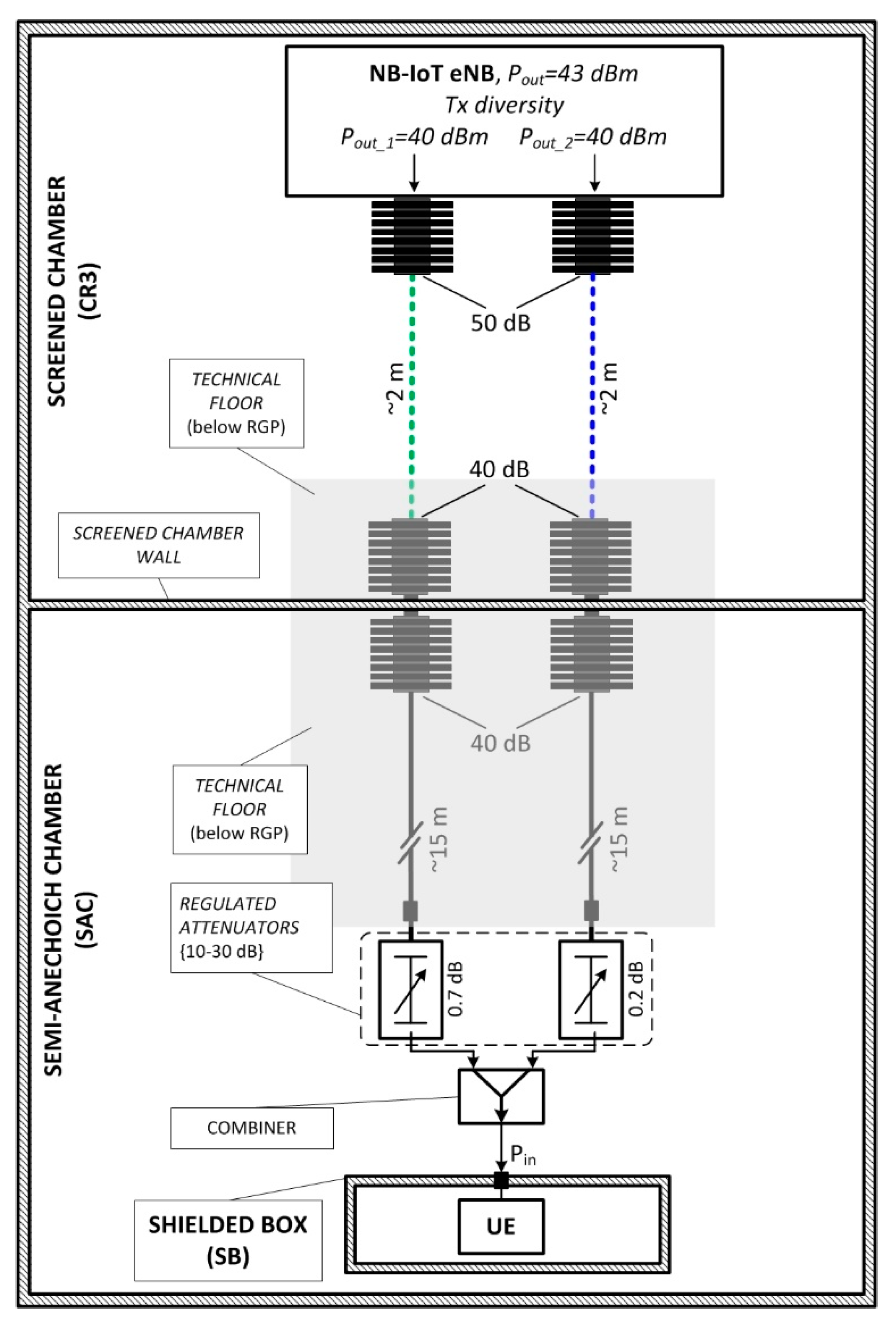
4.1. The Infrastructure for Generating Ultra-high Attenuation

Credible measurements of the system performance under boundary MCL conditions (i.e., close to 164 dB) were performed experimentally under laboratory conditions. For this purpose, a measurement setup was built based on cable tracks in facilities of the specialized Laboratory of Electromagnetic Compatibility (EMC), located at Wroclaw University of Science and Technology. In order to provide a repeatable, fully controlled, interference-free setup for bidirectional, extremely high pathloss measurements, a cable track was assembled as shown in Figure 2. Variable attenuation of the cable tracks was used to simulate the air interface with an ultra-high MCL, as is required for testing NB-IoT systems. Building the test setup in limited space with the use of imperfect elements (i.e., with parasitic leakage of the signal and limited shielding effectiveness), as well as the use of attenuators with high attenuation (40–50 dB) in the cable track, yielded possible unwanted couplings between the signal track segments, leading to the lack of a fully controlled and repeatable test setup. To avoid these unwanted couplings, each attenuation stage was located in one of the three separate chambers, electromagnetically isolated from the others. The specific chambers are identified in the figure as CR3 (for the control room), SAC (for the semi-anechoic chamber) and SB (for the shielded box), each providing isolation exceeding 80 dB. During the measurements, both the NB-IoT core segment and the eNB were located in the CR3 chamber, whereas the test UE was locked in the SB placed in the SAC. As shown in the schematic (Figure 2), the end-to-end connection was provided by means of cable transmission lines and attached attenuators. From the eNB side, to implement transmission diversity, radio-frequency (RF) signals with 40 dBm of power at each of the two outputs were passed separately to the UE through 50 dB fixed attenuators, which were connected directly to each eNB output.
The signals were then passed simultaneously along each line through respective grommets on the penetration panel separating the CR3 and SAC, on both sides of which 40 dB fixed attenuators were attached. Thereupon, by using the RF cabling laid down beneath the reference ground plane (RGP). In fact, for the SAC’s floor, the signal was eventually guided to the turn table located at the opposite part of the SAC and to the last stage of attenuation. The final adjustment (0–30 dB) of the pathloss attenuation was attained by means of manually controlled attenuators, as opposed to the former use of remote-controlled attenuators, which could not provide stable and reproducible attenuation conditions. The outputs of the regulated attenuators were fed into the signal combiner and passed on to the SB inlet, leading directly to the NB-IoT UE placed inside. Considering the combined attenuation of the three fixed attenuators (totaling 130 dB), the total cabling loss (approximately 13 dB, varying by the track), and the intrinsic attenuation of the regulated attenuators (0.2 dB and 0.7 dB), the desired pathloss of about 164 dB was achievable by adjusting them within a range from 10 dB to 30 dB. Measurements of each section attenuation and the received signal level confirmed that the developed test set-up could emulate high pathloss values, guaranteeing stable conditions required for testing the NB-IoT performance. Moreover, based on the measured eNB’s transmitter output power and the test set-up attenuation, values of the signal power at the input of the UE could be determined with high precision. These were then compared to the indications of the UE. For better validation of the MCL achieved during the performance tests, the above procedure was carried out for two UEs from different vendors.

4.2. The NB-IoT Operational Scenarios and Settings

Measurement-based investigations were carried out by testing the performance of both NB-IoT uplink channels (i.e., NPUSCH and NPRACH) in standalone deployment. To yield representative results, attention and special care were paid to carry all the experiments out in a systematic manner. For this reason, a set of 15 measurement scenarios was created, each corresponding to a different combination of the {MCS;Nrep} pair for NPUSCH performance, and a set of 4 measurement scenarios was proposed to cover NPRACH performance verification of the detection success ratio in the function of the repetition number. By being able to control the link attenuation between the eNB and NB-IoT UE with the aforementioned <1 dB precision, its magnitude for each scenario was first set to a relatively low value of 145 dB, for which the entire set of uplink messages in both analyzed channels could be received with a 100% success rate. Then, the attenuation (pathloss) was increased in 2 dB steps until connectivity was completely lost, which corresponded to 0% of successful detections of NPUSCH or NPRACH messages at the eNB.
Such a procedure allowed us to obtain smooth profiles of the passages between 0% and 100% of the successfully received NPUSCH uplink messages (see Figure 3). Each profile represented one of the aforementioned combinations of two adjustable transmission factors, namely the MCS (its three settings being 0, 5, and 10) and the number of repetitions (with 5 settings of N1, N4, N16, N64, and N128), being the key parameters determining the effective NB-IoT NPUSCH coverage.
NPRACH measurements focused on determining the boundary coverage profiles obtained for the edge values of repetitions (i.e., N1 and N128).
A complete list of other crucial operational parameters used in the experiment can be found in Table 1.

5. Results and Discussion

5.1. The NPUSCH Channel: A Detailed Discussion

As can be seen in Figure 3, where the obtained profiles have been visualized, the detection success ratio (DSR) was accepted as a measure of performance, defined as a percentage of successfully received messages in the investigated uplink channels, before any retransmission happened. Various numbers of repetitions are marked as N1, N4, N16, N64, and N128 in the figure.
As for the analysis of the results, the following conclusions can be immediately drawn:
  • Within each MCS, a separation between points on the five curves, corresponding to the same DSR level, differed within the range of 1.7–4.3 dB, with an average difference of 2.97 dB and a standard deviation σ = 0.57 dB, as is also shown in Figure 4a. These values indicate the impact that each increase in the number of repetitions by a factor of four will have on the NB-IoT uplink performance;
  • Average differences between profiles corresponded to the same values of Nrep, but were obtained for different MCSs, varying in the range of 1.6–3.6 dB, with an average difference of 2.7 dB and a standard deviation σ = 0.31 dB, as is also shown in Figure 4b. These outcomes demonstrate the MCS’s impact on NB-IoT performance;
  • A separation between the profiles corresponding to extreme values of Nrep (i.e., 1 and 128) equaled 9.6 dB for MCS0, 10.4 dB for MCS5, and 11.9 dB for MCS10. The results appear to indicate that, though not remarkably, the number of repetitions seemed to have a greater effect on the higher-order MCS than on the lower-order MCS;
  • It took 10.8 dB for each DSR profile to make a complete transition from 0% to 100%, with the maximum standard deviation from this figure equal to 1.6 dB.

5.2. The NPRACH Channel: A Detailed Discussion

In this part of the investigation, border values of NPRACH repetitions were assumed (i.e., 1 and 128). Additionally, a performance comparison was made between NB-IoT radio chipsets acquired from two different vendors. Two major conclusions that can be derived from observing Figure 5 are the following:
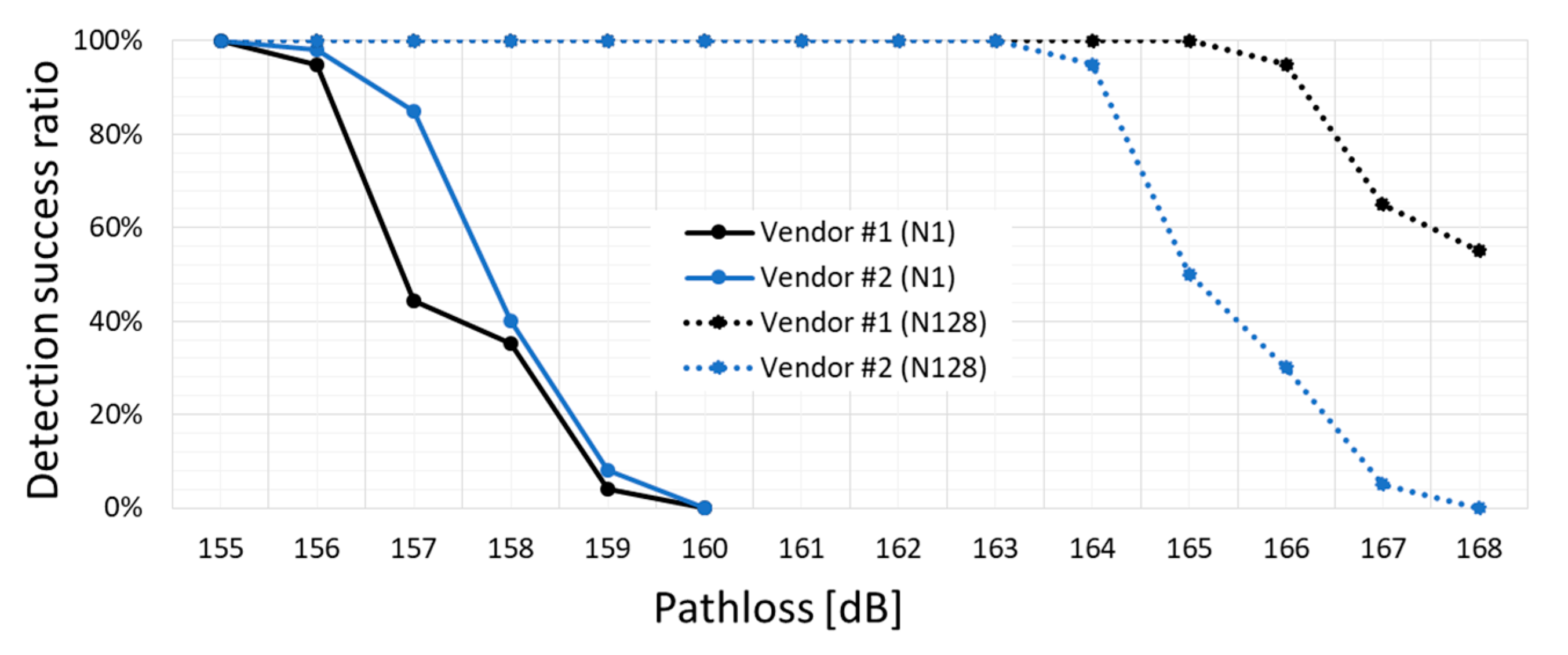
  • An average shift between the performance DSR curves, corresponding to the same percentages, yielded 9.7 dB for Vendor #1 and 8.1 dB for Vendor #2, with σ = 0.26 dB and σ = 0.07 dB, respectively. These small values of σ indicate an almost constant reaction to the change in Nrep from 1 to 128. Both averages, in turn, oscillating at about 9 dB, again indicate a significantly lower response to the change in the number of repetitions than theoretically predicted in the available literature [13,14], according to which 128 repetitions should bring a processing gain closer to 21 dB;
  • Chipsets from both vendors responded similarly; that is, they differed on average by 0.6 dB (with σ = 0.36 dB) when no extra repetitions (N1) were used (solid curves). Concerning the highest number of repetitions (N128), this separation between the two performance curves extends on average to 2.2 dB, with σ = 0.28 dB (dotted curves).

5.3. Comparison of Performance between NB-IoT and Other LPWAN or UNB Systems

The outcomes discussed in the paper can be also directly related to those obtained for systems representing other IoT families, such as LPWAN or UNB (refer to the classification shown in Figure 1). In the authors’ own previous investigations, documented in [29,30,31], the performances of IoT systems, such as LoRa, Weightless, and SigFox, were measured against interference and channel fading. Although results obtained therein relate the DSR to the carrier-to-noise and interference ratio (CNIR), this can be easily converted into the MCL by Equation (1) to compare it with NB-IoT performance. The calculated values of MCL were then gathered in Table 2, in which the last column indicates the MCL, allowing one to notice how the NB-IoT, with MCL = 164 dB, outperformed its LPWAN and UNB counterparts by at least 7 dB when compared with SigFox, and in further excess of this figure when compared with the other systems:
MCL [ dB ] = EIRP [ dBm ] ( 174 [ dBm / Hz ] + BW [ dBHz ] + CNIR [ dB ] )

6. Conclusions and Future Research

Performance-enhancing mechanisms were examined with respect to their impact on successful detection of the two NB-IoT uplink channels, the NPUSCH and the NPRACH. The number of repetitions, Nrep, and the modulation-coding scheme, MCS, were considered for NPUSCH configuration. Additionally, the impact of NPRACH repetitions was examined. The purpose behind the investigations presented in this paper was to emulate a real-life propagation environment with extremely high pathloss in order to force the NB-IoT radio modules to operate at their performance boundaries, which is to say near the MCL = 164 dB point, at which the system is still required to operate. The experiment was thus intended to provide measurement-based verification to theoretical speculations found throughout the available literature or derived from simplified measurements, in which NB-IoT operation was investigated at operational regions far from the extreme MCL edge. As could be expected, measurements performed with the use of the carefully assembled measurement setup in a specialized EMC laboratory provided figures that confirmed the anticipated effect of repetition mechanisms on performance in the qualitative sense (in the sense of the positive effect of an increasing number of repetitions on the performance), albeit not in the quantitative sense (by falling short of the expected absolute improvement in decibels).
In particular, the following findings have been attained and confronted with figures predicted in the available literature (if available). These conclusions can be treated as practical recommendations regarding the handling of basic channel settings in order to plan and optimize NB-IoT operation:
  • As shown in Section 5.1, the measured impact of Nrep on both NPUSCH and NPRACH performance appears to equal roughly 3 dB per every two-fold increase in repetitions. Thus, it is two times less significant than the claimed average 3 dB improvement per every doubling of Nrep, as predicted in [13] or measured with a simplified set-up in [14];
  • As was also demonstrated in Section 5.1, transiting MCS between its extreme settings (i.e., from MCS0 to MCS5 and then from MCS5 to MCS10) caused NPUSCH performance to degrade by about 3 dB per each transition. The entire attainable scope of change in performance thus equaled 6 dB, which was equivalent to the effect obtained when switching Nrep between 1 and 64, as stems from the finding in the previous point;
  • The outcomes presented in Section 5.2 reveal that differences between vendors providing the radio module chipsets are rather insignificant (i.e., falling below 1 dB) for the NPRACH channel when no repetitions are used (N1), but grow up to above 2 dB at N128.
Future investigations of NB-IoT performance are intended to cover the following aspects:
  • Investigate the channel performance of NB-IoT inband and guardband deployments;
  • Investigate the NB-IoT under slowly varying multipath conditions by carrying out measurements in artificially emulated fading channels (i.e., extended pedestrian - A (EPA) and extended typical urban (ETU), defined originally for LTE [32], assuming a 1 Hz Doppler shift in both (after [12]);
  • Investigate the impact of inter-cell interferences, including the coexistence of NB-IoT and LTE systems;
  • Investigate NB-IoT performance at different bands.

Author Contributions

Conceptualization, K.S. and B.C.; methodology, K.S., B.C.; software, M.K.; validation, M.K.; formal analysis, K.S. and M.K.; investigation, K.S., Z.J. and M.K.; resources, Z.J. and B.C.; data curation, M.K. and K.S.; writing—original draft preparation, K.S., Z.J. and M.K.; writing—review and editing, K.S. and M.K.; visualization, K.S.; supervision, K.S.; project administration, B.C. and K.S.; funding acquisition, B.C. and K.S. All authors have read and agreed to the published version of the manuscript.

Funding

This research was funded in part by Nokia under EU grant no. POIR.01.01.01-00-0873/16-01 and in part by the Wroclaw University of Science and Technology under statutory fund no. 8201003902/K34W04D03.

Conflicts of Interest

The authors declare no conflict of interest.

Appendix A

A list of acronyms most commonly used in the text:
  • 3GPP—3rd Generation Partnership Project
  • BPSK—binary phase shift keying
  • BW—bandwidth
  • CNIR—carrier-to-noise and interference ratio
  • DSR—detection success ratio
  • EIRP—equivalent isotropic radiated power
  • eNB—evolved node-B
  • LPWAN—low-power wide-area network
  • LTE—long-term evolution
  • LTN—low-throughput network
  • MCL—maximum coupling loss
  • MCS—modulation-coding scheme
  • MISO—multiple input single output
  • NB-IoT—narrowband Internet of Things
  • NPRACH—narrowband physical random access channel
  • NPUSCH—narrowband physical uplink shared channel
  • Nrep—number of repetitions
  • QPSK—quadrature phase shift keying
  • SNR—signal-to-noise ratio
  • TDD/FDD—time-division duplex/frequency division duplex
  • UE—user equipment
  • UNB—ultra-narrowband

References

  1. Technical Specification Group Services and System Aspects; Feasibility Study on New Services and Markets Technology Enablers (Stage 1, Release 14); The 3rd Generation Partnership Project; 3GPP, TR 22.891 V14.2.0; 3GPP Organizational Partners: Valbonne, France, 2016.
  2. Technical Specification Group Services and System Aspects; Feasibility Study on New Services and Markets Technology Enablers For Massive Internet of Things (Stage 1, Release 14); The 3rd Generation Partnership Project; 3GPP, TR 22.861 V14.1.0; 3GPP Organizational Partners: Valbonne, France, 2016.
  3. IMT Vision—Framework and Overall Objectives of the Future Development of IMT for 2020 and Beyond; ITUR M Series; International Telecommunication Union: Geneva, Switzerland, 2015.
  4. Technical Specification Group Services and System Aspects; Feasibility Study on New Services and Markets Technology Enablers for Critical Communications (Stage 1, Release 14); The 3rd Generation Partnership Project; 3GPP, TR 22.862 V14.1.0; 3GPP Organizational Partners: Valbonne, France, 2016.
  5. Technical Specification Group Services and System Aspects; Feasibility Study on New Services and Markets Technology Enablers—Enhanced Mobile Broadband (Stage 1, Release 14); The 3rd Generation Partnership Project; 3GPP, TR 22.863 V14.1.0; 3GPP Organizational Partners: Valbonne, France, 2016.
  6. Technical Spec. Group Services and System Aspects; Feasibility Study on New Services and Markets Technology Enablers—Network Operation (Stage 1, Release 15); The 3rd Generation Partnership Project; 3GPP, TR 22.864 V15.0.0; 3GPP Organizational Partners: Valbonne, France, 2016.
  7. Low Throughput Networks (LTN); Use Cases For Low Throughput Networks; ETSI, GS LTN 001 V1.1.1; European Telecommunications Standards Institute: Valbonne, France, 2014.
  8. Low Throughput Networks (LTN); Functional Architecture; ETSI, GS LTN 002 V1.1.1; European Telecommunications Standards Institute: Valbonne, France, 2014.
  9. Low Throughput Networks (LTN); Protocols and Interfaces; ETSI, GS LTN 003 V1.1.1; European Telecommunications Standards Institute: Valbonne, France, 2014.
  10. System Reference Document (SRdoc); Short Range Devices (SRD); Technical Characteristics for Ultra Narrow Band (UNB) SRDs Operating in the UHF Spectrum Below 1 GHz; ETSI, TR 103 435 V1.1.1; European Telecommunications Standards Institute: Valbonne, France, 2017.
  11. Cellular System Support for Ultra Low Complexity and Low Throughput Internet of Things; The 3rd Generation Partnership Project; 3GPP, TR 45.820 V2.1.0; 3GPP Organizational Partners: Valbonne, France, 2015.
  12. Study on Provision of Low-Cost Machine-Type Communications (MTC) User Equipments (UEs) Based on LTE; The 3rd Generation Partnership Project; 3GPP, TR 36.888 V12.0.0; 3GPP Organizational Partners: Valbonne, France, 2013.
  13. Adhikary, A.; Lin, X.; Wang, Y.-E. Performance evaluation of NB-IoT coverage. In Proceedings of the IEEE 84th Vehicular Technology Conference (VTC-Fall), Montreal, QC, Canada, 18–21 September 2016; pp. 1–5. [Google Scholar]
  14. Chakrapani, A. NB-IoT uplink receiver design and performance study. IEEE Internet Things J. 2019, 7, 2469–2482. [Google Scholar] [CrossRef] [Green Version]
  15. Migabo, E.; Djouani, K.; Kurien, A. An energy-efficient and adaptive channel coding approach for narrowband internet of things (NB-IoT) systems. Sensors 2020, 20, 3465. [Google Scholar] [CrossRef] [PubMed]
  16. Kosiło, T.; Radecki, K.; Marski, J.; Górski, C. Mobile IoT systems in the urban area. Int. J. Electron. Telecom. 2020, 66, 180–185. [Google Scholar]
  17. Ha, S.; Seo, H.; Moon, Y.; Lee, D.; Jeong, J. A novel solution for NB-IoT cell coverage expansion. In Proceedings of the 2018 Global Internet of Things Summit (GIoTS), Bilbao, Spain, 4–7 June 2018. [Google Scholar]
  18. Basu, S.S.; Sultania, A.K.; Famaey, J.; Hoebeke, J. Experimental performance evaluation of NB-IoT. In Proceedings of the 2019 International Conference on Wireless and Mobile Computing, Networking and Communications (WiMob), Barcelona, Spain, 21–23 October 2019. [Google Scholar]
  19. The Internet of Things Report—Narrowband IoT Delivers Insights from the Largest NB-IoT Indoor Measurement Campaign. Available online: https://theinternetofthings.report (accessed on 14 September 2020).
  20. Malik, H.; Alam, M.M.; Le Moullec, Y.; Kuusik, A. NarrowBand-IoT performance analysis for healthcare applications. Int. J. Electron. Telecom. 2020, 130, 1077–1083. [Google Scholar] [CrossRef]
  21. Kavuri, S. Performance Assessment of Narrowband IoT for Intelligent Cargo Transportation. Master’s Thesis, Tampere University, Tampere, Finland, February 2019. [Google Scholar]
  22. World’s First Narrowband IoT at Sea. Available online: https://www.teliacompany.com/en/news/news-articles/2017/sub-pump/ (accessed on 30 September 2020).
  23. Martinez, B.; Adelantado, F.; Bartoli, A.; Vilajosana, X. Exploring the performance boundaries of NB-IoT. IEEE Internet Things J. 2019, 6, 5702–5712. [Google Scholar] [CrossRef] [Green Version]
  24. Evolved Universal Terrestrial Radio Access (E-UTRA); Physical Channels and Modulation; The 3rd Generation Partnership Project; 3GPP, TS 36.211 V16.3.0; 3GPP Organizational Partners: Valbonne, France, 2020.
  25. Evolved Universal Terrestrial Radio Access (E-UTRA); Multiplexing and Channel Coding; The 3rd Generation Partnership Project; 3GPP, TS 36.212 V16.3.0; 3GPP Organizational Partners: Valbonne, France, 2020.
  26. Evolved Universal Terrestrial Radio Access (E-UTRA); Physical Layer Procedures; The 3rd Generation Partnership Project; 3GPP, TS 36.213 V16.3.0; 3GPP Organizational Partners: Valbonne, France, 2020.
  27. Evolved Universal Terrestrial Radio Access (E-UTRA) and Evolved Universal Terrestrial Radio Access Network (E-UTRAN); Overall Description (Stage 2); The 3rd Generation Partnership Project; 3GPP, TS 36.300 V16.3.0; 3GPP Organizational Partners: Valbonne, France, 2020.
  28. Evolved Universal Terrestrial Radio Access (E-UTRA); Medium Access Control (MAC) Protocol Specification; The 3rd Generation Partnership Project; 3GPP, TS 36.321 V16.3.0; 3GPP Organizational Partners: Valbonne, France, 2020.
  29. Staniec, K.; Kowal, M. LoRa performance under variable interference and heavy-multipath conditions. Wirel. Commun. Mob. Comput. 2018, 2018, 1–9. [Google Scholar] [CrossRef]
  30. Staniec, K.; Kowal, M. On vulnerability of selected IoT systems to radio jamming—A proposal of deployment practices. Sensors 2020, 20, 6152. [Google Scholar] [CrossRef] [PubMed]
  31. Staniec, K. (Ed.) LPWAN/UNB IoT systems performance investigations. In Radio Interfaces in the Internet of Things Systems (Performance Studies); Springer International Publishing: Cham, Switzerland, 2020; Volume 7, pp. 137–149. [Google Scholar]
  32. LTE. Evolved Universal Terrestrial Radio Access (E-UTRA); Base Station (BS) Radio Transmission and Reception; ETSI, TS 136 104 V8.2.0; European Telecommunications Standards Institute: Valbonne, France, 2018.
Figure 1. A classification of Internet of Things systems.
Electronics 09 01947 g001
Figure 2. A measurement setup for emulating extreme maximum coupling loss (MCL) conditions.
Electronics 09 01947 g002
Figure 3. The narrowband physical uplink shared channel (NPUSCH) detection success ratio profiles for 15 combinations of {MCS;Nrep} parameters.
Electronics 09 01947 g003
Figure 4. Average distances between NPUSCH detection success ratio (DSR) profiles, corresponding to the same Nrep and (a) a different MCS or (b) within the same MCS.
Electronics 09 01947 g004
Figure 5. The narrowband physical random access channel (NPRACH) detection success ratio profiles for two different chipset vendors.
Electronics 09 01947 g005
Table 1. The key narrowband Internet of Things (NB-IoT) measurement settings.
ParameterValue
NB-IoT eNB output power, Pout43 dBm
NB-IoT UE transmission power23 dBm
Type of diversityTransmit, MISO (2 × 1)
NB-IoT deploymentstandalone
Center frequency1810 MHz
Channel width180 kHz
Investigated NB-IoT channelsNPUSCH, NPRACH
NPUSCH settingsFormat 1, single-tone,
3.75 spacing
NPUSCH MCS index{0, 5, 10}
NPUSCH Repetitions number (Nrep){1, 4, 16, 64, 128}
Resource assignment (IRU)3
Table 2. Performance comparison between NB-IoT and low-power wide-area network (LPWAN) and ultra-narrowband (UNB) systems.
IoT SystemIoT FamilyEIRP [dBm]BW [kHz]CNIRmin [dB]MCL [dB]
LoRaLPWAN14125−5142
500−19150
Weightless12.5+10137
100−11149
SigFoxUNB0.1+11157
NB-IoTCIoT23 (in uplink)180+10.4164
Publisher’s Note: MDPI stays neutral with regard to jurisdictional claims in published maps and institutional affiliations.

