Abstract
The microgrid includes a distribution system with low voltage, controllable load, and distributed energy resources (DER). The DERs have been increased in the recent power network to address global environmental concerns, which creates challenges in faults, synchronization, inertia control, etc. As the technologies are getting advanced day by day, the past technology becomes obsolete. The internet of things (IoT) and artificial intelligence (AI) are the most discussed topics to obtain solutions for the challenges. One of the proposed solutions is adaptive overcurrent protection, as it can be used for any grid. In this paper, an algorithm is developed for the adaptive overcurrent relay protection to overcome the challenges of the microgrid with distributed energy resources. Then, the solutions obtained from the adaptive overcurrent protection algorithm network simulation are compared to the traditional overcurrent protection algorithm using the four key points such as selectivity, reliability, sensitivity, and speed to have a good performance in the power network. All the simulation studies are done in the electrical transient analyzer program (ETAP) software environment. Simulation results validate the performance of the proposed algorithm for adaptive protection using the IEEE-9 bus system with a microgrid.
1. Introduction
Due to the environmental and global warming issues, people have been recommending and projecting ideas on the smart grid. Today, the smart grid is a significant concept in the power policy national wide [1,2]. After the smart grid is introduced, the next generation of the grid is the microgrid. The microgrid power system is small-scale with various distribution models [3]. Its main idea is to incorporate a limited number of distributed generators to ideally control them without making the system complex [4]. The distribution models can be hybrid, radial, or interconnected. One prominent advantage of the microgrid is that it has two modes of operation. They are grid-connected and islanded-mode. This is a key player in the next generation of the power network.
There is increased growth of distributed energy resources (DER) in the power grid [5]. The reason is that it can reduce electricity costs as well as greenhouse gas emissions [6]. It can also assist the consumers through reducing the dependence on the main electricity grid. DER has a very low value to generate power [7]. It is usually connected to the low and medium voltage of the distribution network using an inverter.
The key point of adaptive protection is that when a fault occurs, the relay can adjust to the power network conditions [8]. It means that the relay can adjust to the current operational condition of the power system. The adaptive protection relay itself is a digital relay. Since this relay has an automatic setting, this technique applies to do so. In the traditional relay, the setting is fixed with one parameter. The relay does not adapt to the surrounding environment, as it does not have the function of real- time. The adaptive protection relay has a microprocessor, so it can use the real-time function. The faults that cannot be protected by the traditional relay, the adaptive protection, can protect the system with a no-fault error.
During the modeling of a modern power system, it recognized two factors that could affect the system. They are the analyzation and isolation of the fault. If a fault happens, it should be isolated fully. To keep the load safely, the affected regions in the main system or the neighboring areas should isolate the fault very fast, no matter how big or small the fault is. The existing protection methods and relay setting can lead to inappropriate tripping, as the evolvement of the grid needs protection such as adaptive protection, which can get the most use of the protection [6]. As the technologies get advanced day by day, the protection relay also has to be advanced. Therefore, adaptive overcurrent protection is one of the effective solutions, as it can be used for traditional networks as well as future grids.
This paper presents the data on the digital relay and the challenges of the microgrid. This paper contributes to an algorithm that is developed for the adaptive overcurrent relay protection to overcome the challenges of the microgrid with distributed energy resources. The adaptive overcurrent protection will be shown in the microgrid connected to the IEEE-9 bus system simulation at the same time other protection types are showcased as well.
The remaining of the paper is organized in the following manner: Section 2 contains a discussion on the challenges of the microgrid. Section 3 will discuss the possible solutions for the challenges. Section 4 will emphasize the distributed energy resources and impacts. Section 5 will explain the proposed algorithm protection. Section 6 presents the validation and verification of microgrid simulation studies. Section 7 discusses the results. The conclusion is summarized in Section 8.
2. Challenges for Microgrid Protection
Without a major adjustment in the microgrid, the traditional protection that is used for the radial distribution network cannot be used [9]. The topology adjustments of the microgrid and level of fault current are for both modes, which are the island mode and grid-connected mode. The major challenge in the microgrid would be the integration of distributed energy resources. The following are the challenges for the microgrid protection system.
2.1. Oscillography Data
The fault current is dependent on the operational mode of the microgrid. The utilities contribute to the fault current of the microgrid, while for the islanded mode, the potential fault current is low. The fault current decreases when there is an increase in the feeder, as the fault shifts downward along the feeder path for the conventional distribution network. However, for the microgrid, the distributed energy resources contribute to the fault current as well. There will be two different fault currents path for grid-connected and island mode. It will need two different relay settings. It is not practical to have a fixed relay setting for the microgrid system. The reason for that is the DER’s behavior would affect the relay setting coordination.
2.2. Microgrid Topology Impact on Protection
There will be an effect on the direction and the magnitude of the fault current in the microgrid if the network is in a meshed or looped configuration. Here is an example. In a loop network, the fault current is divided into two parallel lines. Therefore, the current from the upstream protective device feeder will be twice as large as each fault within the loop. The microgrid will have an impact on the coordination of the protective device if the network is meshed or looped.
3. Possible Solutions for the Challenges
The following are the possible solutions for the above-mentioned challenges.
3.1. Adaptive Protection
Each grid-connected and islanded mode will have its own set of relay settings. When the microgrid switches the operational mode, the relay will choose the best setting for that particular mode. For the islanded mode, the time overcurrent characteristic curve of the relay will be changed to instantaneous and/or definite time overcurrent relay settings to low fault currents. Since the adaptive protection relay is a digital relay, the relay’s setting would adjust the operational mode of the network. One example would be when there is a large voltage depression case, the restraint voltage overcurrent protection would decrease delay tripping, which is the time dial in the relay setting.
3.2. Differential Protection
This protection is used on the coupled differential directional relays. It can accurately identify the location and remove the fault without disrupting the components in the system. This protection is used in traditional protection technologies. However, it can be used for both islanded mode and grid-connected in the microgrid. Differential protection can be either localized or centralized. The definition of centralized means it is coordinated and monitored by the central controls. The definition of localization means it is created from the local communication among the relays. The localized scheme, which is more acceptable for applications of the industry, allows communication directly among the relays where the fault will have the fastest solution for it. In the centralized scheme, the topology of the microgrid and power device’s setting operation is monitored by the central controllers. Then, the tripping of the command is sent to the power device when the fault is sensed. This scheme provides precise results with an unacceptable time delay to do calculation, which is required by the central controllers.
3.3. Real-Time Closed-Loop Test to Adaptive Protection in a Smart-Grid Context
The purpose of this research is to show the viability of real-time and automated adjustment in the setting of commercial relay protection. To illustrate it, a commercial protection relay and Real-Time Digital Simulator (RTDS) with a closed-loop test rig used to set up. The commercial relay protection uses the theory of adaptive protection while the RTDS set is real-time automated with various functions of protection.
The first test is about testing smart substation control (SSC) using a real-time closed-loop test. The equipment for the setup is an RTDS and EFACEC TPU S220, which is the commercial relay. Using the network’s actual state, the SSC can verify whether the network is in a sympathetic tripping situation. The SSC collects real-time information from the local sensors to know the network’s actual state and the sympathetic tripping evaluation. Based on the SSC mode of operation, to avoid sympathetic tripping, the protection group values of the feeder relay might alter.
The second test is the adaptive protection test. For this test, the researcher has done two case studies: one where the SSC was halted, and the other one was SSC activated. The preset of the parameters and functions of the protection relay is controlled by the SSC to change automatically when the SSC is activated. Under the SSC, there are two setting groups. They are default settings and sympathetic tripping. The default setting is named group 1, while the setting for sympathetic tripping is group 2. Once the SSC senses the possible occurrence of synthetic tripping, it will change from group 1 to group 2.
3.4. Dual Complex Adaptive Protection Algorithm for Microgrid
The power demand has been growing, and the traditional energy sources are depleting. So, the penetration of DERs has been introduced to the microgrid. Therefore, the microgrid cannot use the conventional power protection scheme [10]. The power flow of the microgrid is bidirectional. Therefore, it affects the operation of the protection as well as coordination. In the traditional power grid, the power flow is one-directional.
Therefore, one of the researchers has projected the dual simplex algorithm for the novel adaptive overcurrent protection for a microgrid. The projected algorithm should be able to detect the operation time and time multiplier setting (TMS) of the relay for a given microgrid type. This information is saved in the lookup table, which is in the central protection system. The lookup table should find suitable protection coordination when there is a fault in the microgrid.
4. Distributed Energy Resources
Distribution protection has been significantly impacted by the penetration of distributed energy resources (DER) [11]. Many components affect the current flow during the load flow and short-circuit analysis. They are generated power, short-circuit contribution, and the operating state of DERs. Maintaining the feeder, DERs, and monitoring the protection’s selectivity and sensitivity with a quick response is challenging when there is a greater integration of DERs.
4.1. Time Consuming
As the network changes over time, it is difficult to coordinate and analyze the distribution system protection and the time characteristic curve (TCC). The coordination of the protection should be checked throughout in every switching device and the volatile output of DERs. This means that the engineers must do many analyses of the TCC until they get the correct protection coordination for the device. For the above scenarios, some revision needs to be done in the setting where the protection engineers need reconfirmation of the new protection setting.
4.2. Impact of Voltage Device Stability
During the generation process, the present feeder loading patterns change due to the DER’s interconnection, and the correct voltage value will also be changed [12]. The loading pattern will be changed by the DER along with the feeder. The previous load pattern, which is set by the existing voltage device control, may no longer deliver the correct voltage regulation. The design of the existing devices should be able to provide an acceptable steady state of the voltage regulation. It is from zero to full load. The impact might be less when the DER is only serving at the local load. The voltage devices such as voltage regulators, transformer load-tap-changing (LTC), and capacitors will have to study accurately to accommodate DER. This will happen when the DERs are at a higher level and reverse flow is encountered.
4.3. Impact of the Fault Duty of Circuit Breakers
Before installing the DER, the circuit breakers are planned in the network regarding which circuit breakers are to be opened when a fault occurs. DER is an example of generation sources. Therefore, the DER will be added to the accessible fault duty on distribution feeders. In the radical direction, the present relays are set to operate. It is coordinated such that customer interruption is less with the downstream protection devices. It is done by introducing DER coordination changes. In addition, having more DERs on the feeder means that there are many sources, and coordination becomes complex.
5. Algorithm for Adaptive Overcurrent Relay Protection
Adaptive overcurrent protection is more efficient than traditional overcurrent protection. The traditional overcurrent protection relay is not flexible in adjusting to the network parameters automatically. It must be done manually. This might lead to the wrong isolation of the fault. However, for adaptive overcurrent protection, it uses real-time values automatically and isolates the fault very fast. Therefore, there is less or no wrong isolation of the fault. The reason why adaptive protection is more effective than traditional protection will be explained under discussion using the four key points.
An algorithm is developed for adaptive overcurrent relay, which is explained as follows.
The flowchart of the algorithm is given in Figure 1. The new adaptive relay connected to the network will firstly do an auto-calibrate. After that, the parameters of , Time Dial Setting (TDS), and the fault current will be preset to zero. Following, it will do a Newton–Raphson analysis, which is the load flow and short-circuit analysis. Then, it will calculate the . The 1.5 in the represents the safety margin [13].
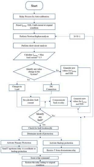
Figure 1.
Algorithm of adaptive overcurrent protection.
Then, the relay will check for any changes in the system. If there is no change, it will calculate for new TDS. However, there is a change to the system when the load value changes or the distributed generator (DG) connection value changes. All the necessary changes for load or DG are communicated through the relay. This results in a new set of parameters for and TDS generated.
The next step is identifying the fault and its location by using the overcurrent equation, which is denoted by “(1)” in the algorithm.
The principle of overcurrent protection is shown in (1).
In the overcurrent principle, there are two conditions. The first condition is “Normal Condition”, where there is no fault. The relay will not operate for circuit breakers (CB) to trip, which means that I’ is smaller than the . T is the representation of the second condition, which is the short-circuit fault condition. When I’ is greater the , the relay determines the mode of operation.
After determining the mode of protection, it issues a command for which CB to trip. Once the fault is cleared, it will restore to the original condition. It continues to do the same process for the next iteration where .
Implementation of the Algorithm in an Existing Distribution System
The developed algorithm can be implemented in the actual distribution system using supervisory control and data acquisition (SCADA) and ETAP Real-Time. The latest ETAP software should be used for the implementation.
The information system portrays a key importance in the application of new ideas in the control and monitoring of the power network [14]. The new feature in the SCADA system is the state estimation concept. It supports the advancement of the information system and automation schemes. The SCADA system uses real-time in ETAP software which, in turn, allows the execution of the state estimate.
Real-time simulation is one of the needs that Engineers use these days. It uses the execution of new solutions in monitoring, the control system, and automation. This concept is created as the foundation for a combination of two technologies for the simulation of control systems and monitoring.
The real-time not only has characteristics for dynamics but also has physical counterparts for a correct simulation time of response. The time required for simulation to produce improvements or results is roughly about the time needed for the actual system. The latest technology has allowed the exchange of data across the telecommunication protocols to be improved. In the electrical system, it is taken as part of the control and monitoring of the system.
The SCADA plays a key role in the execution of an autonomous system. It makes sure the power system has high efficiency and security in the system, the quality, and permanence of the power supply. The current applications of a SCADA system are increasing. It can analyze and obtain the data that is from an online connection.
The state estimator concept is used by the ETAP real-time application. The application needs the power network’s model for load flow calculation as well as measurement integration. It is for collecting online data by using communication protocols.
Based on the above concepts, it should be able to implement the algorithm in the actual power distribution system.
6. Validation and Verification of Microgrid Simulation Studies
Figure 2 represents the IEEE-9 bus system connected to a microgrid system [15]. In this system, there are three wind turbine generators (WTG) with different parameters being used. Adaptive overcurrent protection and differential transformer protection are being used in this system.
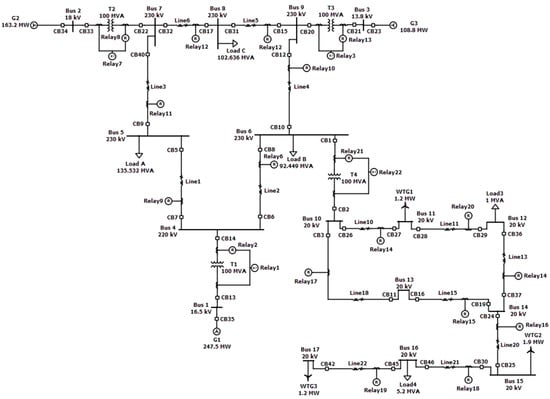
Figure 2.
IEEE-9 bus system with microgrid network.
The tripping of the protection relay happens when a fault occurs based on the following equation.
The is the tripping time of the relay, while , , and are the time multiplier setting (TMS), fault current, and pickup current, respectively. The fault current always depends on the short circuit fault and the system model. The values of and are relay settings. The value of should be greater than the maximum load current. This is measured by the current transformer and leaving some safety factor (SF). Therefore, the pickup current is calculated in the following manner.
As mentioned before, the value of SF is normally set to 1.5. The following is an example of adaptive protection using the algorithm. Figure 3 shows the steps on how the algorithm works in ETAP software using Line2 having a fault.
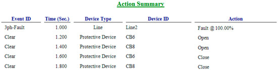
Figure 3.
Action summary.
In simple terms, this action summarizes that there is a three-phase fault at Line3. Then, CB6 and CB8 will start to operate by opening them. Once the isolation is done, both CB6 and CB8 will close. The system is back to normal. The following results are the during and after the fault.
During the fault, CB6 will trip first, followed by CB8 this is shown in Figure 4.
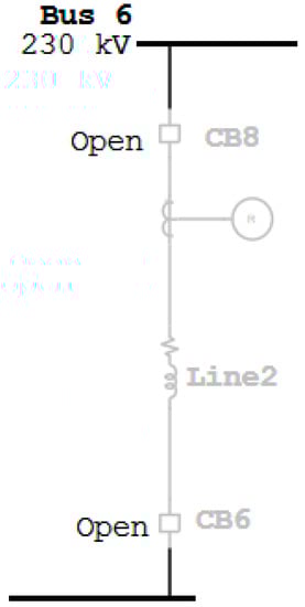
Figure 4.
During the fault.
The below result is when the fault is isolated. After isolating the fault, the system is back to normal.
The ETAP version 16 does not support real-time values; therefore, some parts are done manually. However, the outcome results are still the same and correct.
When a fault occurs between Bus 4 and Bus 6 as shown in Figure 5, CB6 will open first as the primary protection followed by CB8 and CB10 as backup protection. The following is an example of when the power output from the wind turbine value changes. The value will change from 1.2 kW to 3 kW. The fault current changes when there is a change in the value, which can be seen below. It can be concluded that when the wind turbine power increases, the fault current also increases. The following results shown in Figure 5 and Figure 6 are the comparison between the overcurrent protection and developed algorithm of the adaptive overcurrent protection.
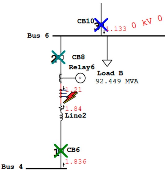
Figure 5.
Adaptive overcurrent protection.
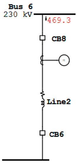
Figure 6.
After isolating the fault.
Figure 7 shows the results when WTG1 = 1.2 kW and WTG1 = 3 kW. Parts (a) and (b) in Figure 7 do not match. The overcurrent relay is fixed at the original parameters, which is at WTG1 = 3 kW. Therefore, the relay needs to recalculate the parameters when WTG1 = 3 kW. The following results are when the developed algorithm of adaptive overcurrent protection is used.
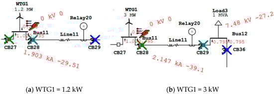
Figure 7.
Overcurrent protection.
However, in Figure 8, part (a) and (b) both get the same tripping sequence. The reason is that adaptive overcurrent relay uses the real-time value. Therefore, there is no need for human intervention. The following figure represents a comparison between the two relays when the load value changes. The load value changes from 1 MVA to 3 MVA.
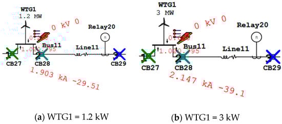
Figure 8.
Developed algorithm of adaptive overcurrent replay protection.
Based on the Figure 9, it can be concluded that using overcurrent protection is not effective if the load value changes. As the overcurrent protection relay does not have the function of capturing the real values automatically, it needs to recalculate manually. However, for adaptive overcurrent protection, it adjusts automatically to the changes. Therefore, adaptive overcurrent protection is more effective than overcurrent protection.
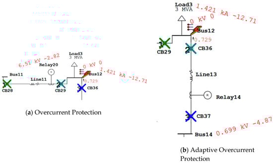
Figure 9.
Comparison between two relays when load value changes.
The following Table 1 is the comparison between the adaptive overcurrent protection and overcurrent protection. Based on the comparison, it can be said that adaptive overcurrent protection relay is a better option than overcurrent protection. The reason for that is if a fault occurs, adaptive overcurrent relay will isolate the fault accurately and quickly for all the scenarios mentioned. However, for overcurrent protection, when there is no change in the network, the isolation will be correct on its first try. For the rest of the scenarios, the correct isolation will happen after many attempts.

Table 1.
Comparison between the two relays.
The following Table 2 is the representation of the tripping sequence between two buses.
Table 2.
Tripping sequence between two buses.
The transformers will be protected by differential transformer protection, which is denoted by relay 87. It only protects the internal fault of the transformer and does not protect any external fault. By adding an overcurrent relay, it will protect the external faults of the transformer. Figure 10 is an example of the external and internal fault of a transformer. These results are based on when WTG1 = 3 kW.
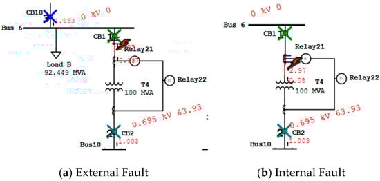
Figure 10.
External and internal fault of transformer.
For this simulation, Relay 21 operates as the created algorithm adaptive protection. However, the internal fault that is operated by Relay 22 will only trip CB1 and CB2. The results for the rest of the transformers are shown in Table 3.
Table 3.
Tripping sequence for external and internal faults of the transformer.
There is no backup protection for any transformer internal fault. However, in order to have backup protection, an overcurrent relay connects to it. For this simulation, an adaptive overcurrent protection algorithm is being used.
7. Discussion
To establish a good performance of a relay in the distribution network, four key characteristics are used when choosing a relay. They are selectivity, reliability, sensitivity, and speed [16].
- Selectivity: When operating a fault, only a small number of fault interruption devices should be used.
- Reliability: The precision of the functioning relay. The precision is determined by the following equation.
Under reliability, there are two key essentials. They are dependability and security. Unwanted actions are removed under security. Dependability is how precise the tripping of the circuit breaker is when a fault occurs. Security can be improved by the selectivity of the system relay, while dependability can be improved by having a higher sensitivity level in the system relay.
- Sensitivity: The protection relay in the system should sense the smallest fault current value. More sensitivity means when the protection relay can sense the smallest value of the fault current. Improving the efficiency of the sensitivity is by looking for that specific thing that makes the fault unique. The faults that happened in the system may not be the same every time.
- Speed: How quickly the relay can isolate the fault when a fault occurs, without interrupting the unaffected zones of the network.
Based on the above characteristics, the comparison between two protective relays (overcurrent relay and adaptive overcurrent relay) is shown in Table 4 below. This comparison is done based on the results of Figure 7 and Figure 8.
Table 4.
Comparison between overcurrent relay and adaptive overcurrent relay.
Based on the above table, it shows that adaptive overcurrent protection is a better option compared to overcurrent protection. The main reason is the adaptive overcurrent protection quickly isolates the fault without disturbing the unaffected area, even when DGs are connected. That is because this relay can achieve real-time values. It is not fixed at one value. However, overcurrent protection is not effective when DGs are connected. The current value changes and is fixed to operate at one value. This can be seen in Figure 6 and Figure 7. In addition, the algorithm of adaptive overcurrent relay protection can be used for any type of grid and is not fixed to one. However, it is more effective to use in any smart-grid system.
Before the digital relays, conventional relays were famous. The idea of the digital relay was spread around in 1985 [17]. One example of the digital relay is the adaptive overcurrent relay. By comparing to the conventional relay, the digital relay has more functions on the monitoring side. In terms of the usage, the functions are flexible [18]. The digital relay can create complicated functions. The efficiency is high, and it can interconnect with other digital equipment. The digital relay has more advantages over conventional relay. The following are the most noticeable advantages. It is easy to control and set up. The action of the operation is fast. There is a communication line between the various relays and the protection coordination. This helps isolate the fault fully.
7.1. Disturbances in the Electrical Grid
Due to the power quality disturbance in the industrial electrical grid, the algorithm might not work accurately as compared to the ETAP software. The main reason for this is power quality disturbance. The ETAP software assumes all the power quality disturbances are taken care of by the software itself. However, in the industrial electrical grid, the power quality disturbances have to be taken into consideration.
Supraharmonic emission is something new and can affect the infrastructure of any kind of smart grid. PLC communication is one example of it. Due to today’s new electronics, this emission has increased. Energy efficiency devices for domestic uses and power electronics are included as a key source of supraharmonic emission in the smart grid. The following are some of the sources with the emission frequency [19].
- PV inverters: 4–20 kHz
- EV chargers: 15–100 kHz
- Domestic devices: 2–150 kHz
- Streetlamps: Up to 20 kHz
- Converter (Industrial-size): 9–150 kHz
It is harder to identify supraharmonic emission when comparing to harmonic emission for a traditional grid. There is a standard harmonic emission set for PV installation and equipment with low voltage. Therefore, they are not categorized as supraharmonic emissions.
7.2. Solutions for DERs Challengers
There are challenges for having many DERs in the network, which will be mentioned in the following [20]. The first one is that during island mode, the current control strategy is not able to work. The reason for that is no main energy source. The second one is that the microgrid needs fast regulation in the islanded mode because there are many capacities in multiple strategies. The last one is that when the DERs values are high, there is a problem in the distribution network. The problems are the voltage and network frequency being unstable and voltage level rise. The microgrid can solve such problems.
The following are some of the solutions to the challenges. Using the DER’s options, system reliability and flexibility can be improved. Then, the generation efficiency can be improved by the DER’s waste heat. Another one is without disrupting the public grid operation, the integration of DER can be done by permitting the power network to inspect and control the fault more effectively. At the same time, the damage caused by the disruption of the DER should be reduced by constantly feeding critical loads.
8. Conclusions
This paper presents the challenges for microgrid protection as well as possible solutions for the challenges when the distributed energy resources are involved. Using a microgrid network, both overcurrent and adaptive overcurrent protection are compared using the characteristic of choosing a relay. The most efficient protection relay is adaptive overcurrent protection based on the four key points. It is automatically adapted to real-time changes. The conventional relay is fixed at one parameter. It can be concluded that conventional relays are more efficient in the traditional power system, while adaptive overcurrent relay is suitable for any type of grid. An algorithm is proposed to overcome the challenges with the modern power network, such as a microgrid with distributed energy resources. The test results for various types of faults such as line faults, transformer faults, and faults when the wind turbine generators are connected in the system of the IEEE 9 bus network with a microgrid demonstrate the effectiveness of the proposed adaptive overcurrent protection algorithm. In addition, details are provided to protect the internal and external fault of the transformer. The performance of the proposed algorithm is compared with the conventional protection. Therefore, this paper proves that traditional types of relay protection are not efficient for these types of modern power networks such as the smart grid, and hence, this paper contributes to implementing the adaptive overcurrent protection for an advanced power network with distributed energy resources. Adaptive overcurrent protection will be one of the useful and effective protection in the upcoming networks as there will be technologies such as AI and IoT, which uses real-time values.
Author Contributions
Conceptualization, C.C., T.N.R. and T.L.; methodology, C.C.; software, C.C.; validation; C.C.; formal analysis, C.C.; investigation, C.C.; resources, C.C., T.N.R. and T.L.; data curation, C.C.; writing—original draft preparation, C.C.; writing—review and editing, C.C., T.N.R. and G.P.; visualization, C.C. and T.N.R.; supervision, T.N.R. and T.L.; project administration, C.C. and T.N.R.; funding acquisition, T.N.R. All authors have read and agreed to the published version of the manuscript.
Funding
This research received no external funding.
Conflicts of Interest
The authors declare no conflict of interest.
References
- Chandraratne, C.; Naayagi, R.T.; Logenthiran, T. Smart grid protection through self-healing. In Proceedings of the 2017 IEEE Innovative Smart Grid Technologies-Asia (ISGT-Asia), Auckland, New Zealand, 4–7 December 2017; pp. 1–6. [Google Scholar]
- Zhou, J.; He, L.; Li, C.; Cao, Y.; Liu, X.; Geng, Y. What’s the difference between traditional power grid and smart grid?—From dispatching perspective. In Proceedings of the 2013 IEEE PES Asia-Pacific Power and Energy Engineering Conference (APPEEC), Hongkong, China, 8–11 December 2013; pp. 1–6. [Google Scholar]
- Danish, M.S.S.; Matayoshi, H.; Howlader, H.R.; Chakraborty, S.; Mandal, P.; Senjyu, T. Microgrid Planning and Design: Resilience to Sustainability. In Proceedings of the 2019 IEEE PES GTD Grand International Conference and Exposition Asia (GTD Asia), Bangkok, Thailand, 19–23 March 2019; pp. 253–258. [Google Scholar]
- Hossain, M.A.; Pota, H.R.; Hossain, M.J.; Blaabjerg, F. Evolution of microgrids with converter-interfaced generations: Challenges and opportunities. Int. J. Electr. Power Energy Syst. 2019, 109, 160–186. [Google Scholar] [CrossRef]
- Lee, J.; Shin, Y.; Lee, I. The analysis of distributed energy resource trading system for aggregate retail sales. In Proceedings of the 2016 International Conference on Information and Communication Technology Convergence (ICTC), Jeju, Korea, 19–21 October 2016; pp. 1058–1060. [Google Scholar]
- Tushar, W.; Chai, B.; Yuen, C.; Smith, D.B.; Wood, K.L.; Yang, Z.; Poor, H.V. Three-Party Energy Management with Distributed Energy Resources in Smart Grid. IEEE Trans. Ind. Electron. 2015, 62, 2487–2498. [Google Scholar] [CrossRef]
- Song, H.; Srinivasan, R.; Sookoor, T.; Jeschke, S. Smart Cities; John Wiley & Sons: Hoboken, NJ, USA, 2017. [Google Scholar]
- Chandraratne, C.; Logenthiran, T.; Naayagi, R.T.; Woo, W.L. Overview of Adaptive Protection System for Modern Power Systems. In Proceedings of the 2018 IEEE Innovative Smart Grid Technologies-Asia (ISGT Asia), Singapore, 22–25 May 2018; pp. 1239–1244. [Google Scholar]
- Che, L.; Khodayar, M.E.; Shahidehpour, M. Adaptive Protection System for Microgrids: Protection practices of a functional microgrid system. IEEE Electrif. Mag. 2014, 2, 66–80. [Google Scholar] [CrossRef]
- Gupta, A.; Varshney, A.; Swathika, O.V.G.; Hemamalini, S. Dual Simplex Algorithm Aided Adaptive Protection of Microgrid. In Proceedings of the 2015 International Conference on Computational Intelligence and Communication Networks (CICN), Jabalpur, India, 12–14 December 2015; pp. 1505–1509. [Google Scholar]
- Wahyudi, C.A.D.; Hariyanto, N.; Ganjavi, R. Adaptive Protection of Distribution Systems with DERs Considering Consumer and Generation Profiles. In Proceedings of the 2019 International Conference on Smart Energy Systems and Technologies (SEST), Porto, Portugal, 9–11 September 2019; pp. 1–6. [Google Scholar]
- Bravo, R.J.; Salas, R.; Bialek, T.; Sun, C. Distributed energy resources challenges for utilities. In Proceedings of the 2015 IEEE 42nd Photovoltaic Specialist Conference (PVSC), New Orleans, LA, USA, 14–19 June 2015; pp. 1–5. [Google Scholar]
- Sung, B.C.; Lee, S.H.; Park, J.; Meliopoulos, A.P.S. Adaptive Protection Algorithm for Overcurrent Relay in Distribution System with DG. J. Electr. Eng. Technol. 2013, 8, 1002–1011. [Google Scholar] [CrossRef]
- Luna, E.G.; Manrique, R.F.; Bocanegra, E.L.P. Monitoring and Control System Using ETAP Real-Time on Generation Plant Emulation Using OPAL-RT. In Proceedings of the 2018 IEEE ANDESCON, Santiago de Cali, Colombia, 22–24 August 2018; pp. 1–6. [Google Scholar]
- Zanjani, M.G.M.; Mazlumi, K.; Kamwa, I. Application of μPMUs for adaptive protection of overcurrent relays in microgrids. IET Gener. Transm. Distrib. 2018, 12, 4061–4068. [Google Scholar] [CrossRef]
- Mardegan, C.S.; Rifaat, R. Considerations in applying IEEE Recommended Practice for Protection Coordination in Industrial and Commercial Power Systems-Part I. In Proceedings of the 2015 IEEE/IAS 51st Industrial & Commercial Power Systems Technical Conference (I&CPS), Calgary, AB, Canada, 5–8 May 2015; pp. 1–10. [Google Scholar]
- Al-Nujaimi, A.; Al-Muhanna, A.; Zerguine, A. Digital Signal Processing Effect on Power System Overcurrent Protection Relay Behavior and Operation Time. In Proceedings of the 2017 9th IEEE-GCC Conference and Exhibition (GCCCE), Manama, Bahrain, 8–11 May 2017; pp. 1–5. [Google Scholar]
- Raja, I. A Comprehensive Study of the Impact Analysis of Facts Devices on Relay Protection and Its Mitigation. Ph.D. Thesis, Anna University, Tamil Nadu, India, 2016. [Google Scholar]
- Eid, B.M.; Rahim, N.A.; Selvaraj, J.; el Khateb, A.H. Control Methods and Objectives for Electronically Coupled Distributed Energy Resources in Microgrids: A Review. IEEE Syst. J. 2016, 10, 446–458. [Google Scholar] [CrossRef]
- Rönnberg, S.; Bollen, M. Power quality issues in the electric power system of the future. Electr. J. 2016, 29, 49–61. [Google Scholar] [CrossRef]


Publisher’s Note: MDPI stays neutral with regard to jurisdictional claims in published maps and institutional affiliations. |
© 2020 by the authors. Licensee MDPI, Basel, Switzerland. This article is an open access article distributed under the terms and conditions of the Creative Commons Attribution (CC BY) license (http://creativecommons.org/licenses/by/4.0/).