1. Introduction
Earth observation and astronomical satellites for acquiring larger-scale, high-resolution images have been developed [
1]. The disturbance generated by flywheels for attitude control and other moving components increases the satellite’s vibration and degrades the resolution of the captured images.
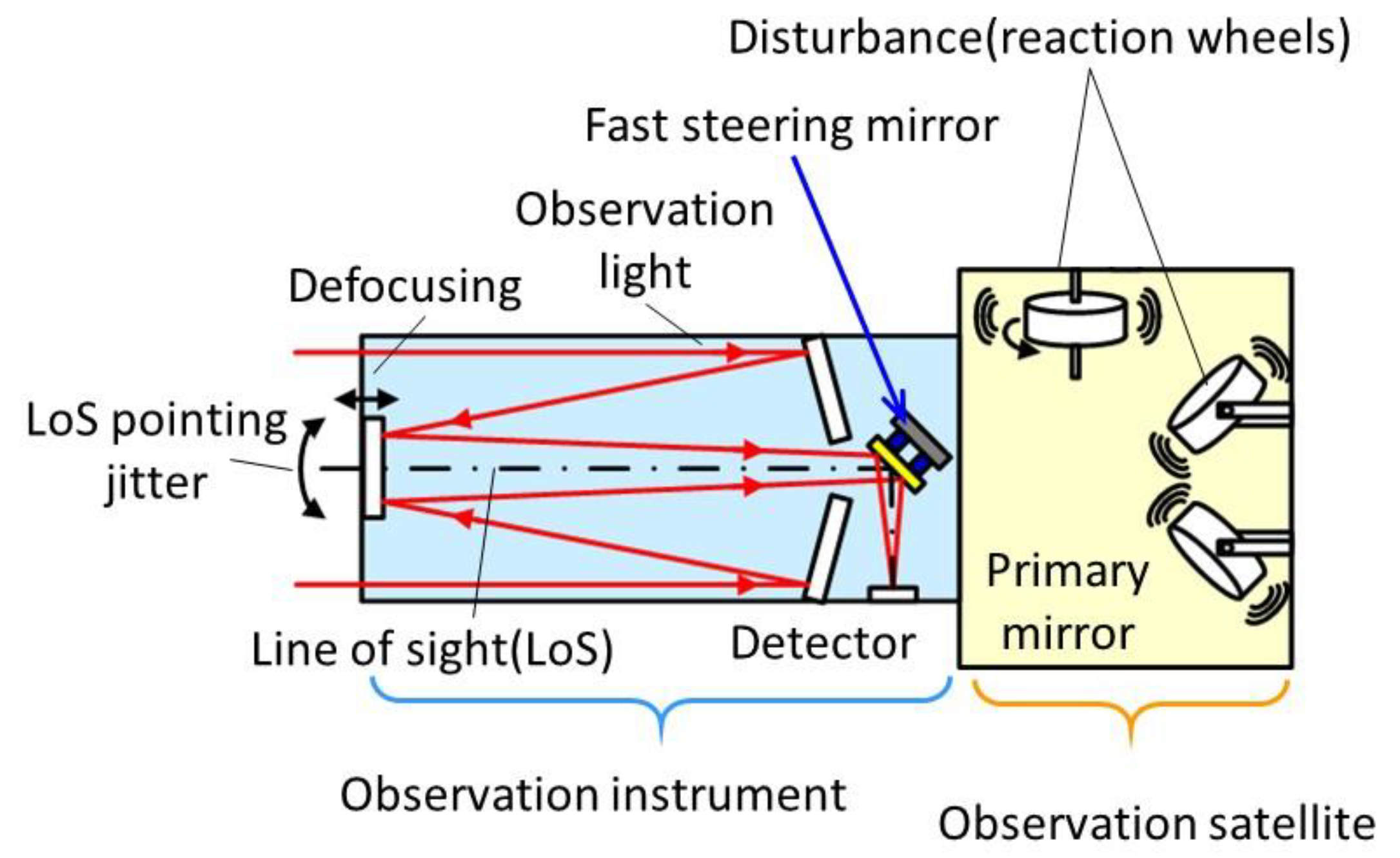
Figure 1 shows that a fast steering mirror (FSM) [
2] positioned in the tip-tilt directions can be used to correct the image blur caused by the vibration of the instrument. The mirror needs to have a large diameter to capture large-scale images. It also has to respond rapidly to compensate for high-frequency vibrations. Rapid response of a large mirror is usually difficult to realize because the larger the mirror is, the more vibration modes the FSM has in the low-frequency range.
Many FSMs have been developed for corrections of images made by observation satellites and for laser systems for inter-satellite communication.
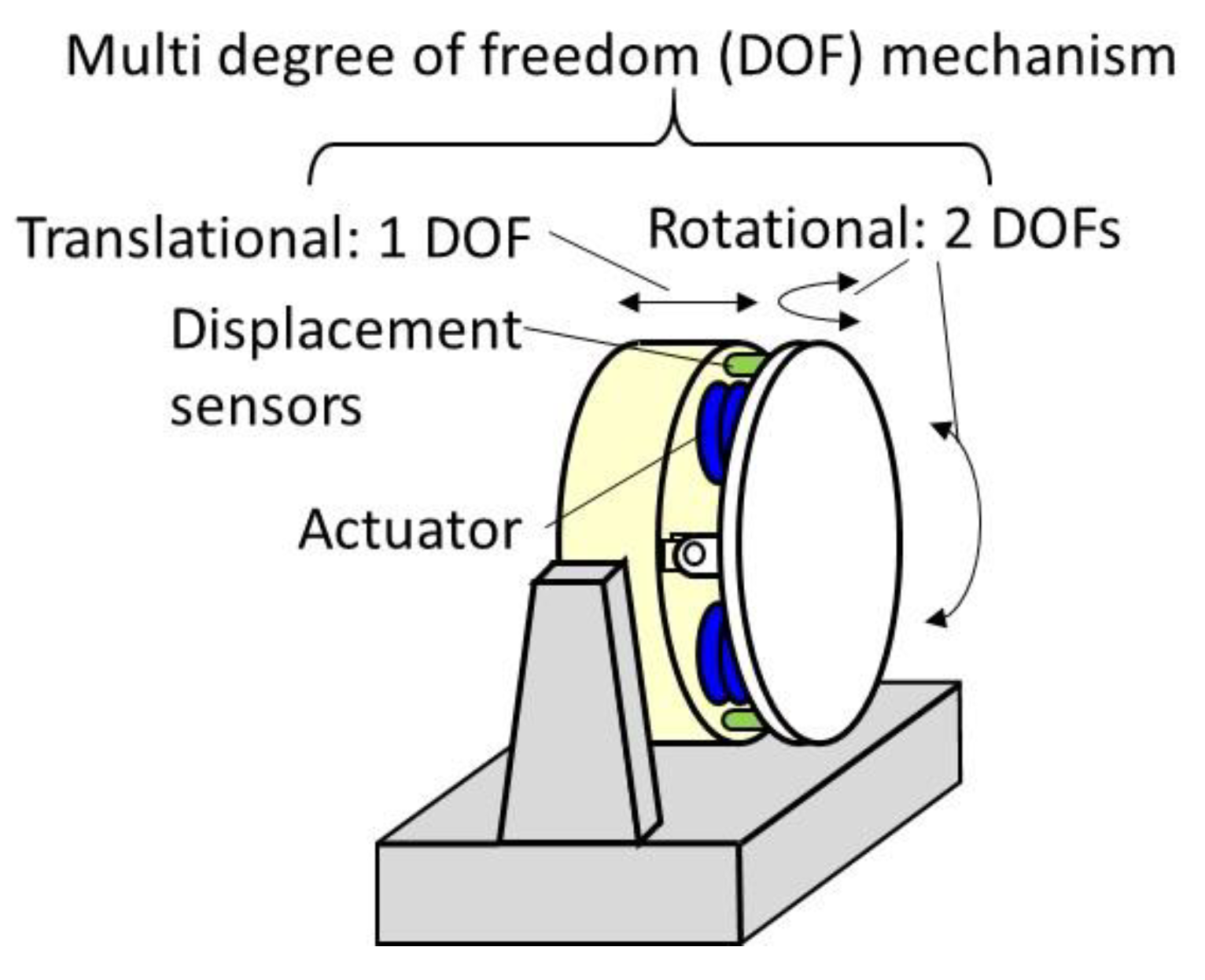
Figure 2 shows a schematic view of an FSM, consisting of a mirror, actuators, displacement sensors, and a guideway mechanism for the tip-tilt motion and axial adjustment of the mirror [
3]. Many types of actuator for driving the mirror, such as rotary motors [
4], voice coil motors (VCMs) [
5], electromagnets [
6], and laminated piezoelectric actuators [
7], have been tested and used. Electromagnets and laminated piezoelectric actuators generate a large force, but the stroke is smaller than that of a VCM, and non-linearity such as hysteresis and saturation is observed in the input/output characteristics. On the other hand, VCMs can respond rapidly with good linearity and have a larger positioning range than either piezoelectric actuators or electromagnets [
5,
6,
7].
Spherical bearings [
8], gimbal mechanisms [
9], elastic rods [
6], and elastic hinges [
10] have been designed and tested to realize the tip-tilt motion of FSMs. Spherical bearings have a wide stroke range and a fixed center of rotation, but the friction and wear degrade the positioning accuracy and the response of the FSM. Gimbal mechanisms using flexure pivots [
11] are free from friction and wear. However, the structure connecting the mirror and the gimbal ring with some flexure pivots decreases the natural frequencies in the uncontrolled directions. Furthermore, the dynamic characteristics of each axis are different due to the mass and inertia of the gimbal ring, and interference between the axes also increases.
A mirror supported by an elastic rod and/or flexure hinges can move without friction and wear, and the guideway mechanism is simple and compact. However, many elastic vibration modes occur in the driving frequency range due to the deformation of the guideway at high frequencies, which destabilizes the feedback system and limits the servo bandwidth. To avoid mode vibration of the mechanical guideways, the use of a magnetic suspension for FSMs has been studied [
12].
In this paper, we propose an FSM using a magnetic suspension to guide the mirror in the tip-tilt and axial directions and suppress other low-frequency vibration modes. The proposed magnetic suspension is compact, simple, and free from friction, wear, and maintenance. Furthermore, axial positioning of the mirror for defocus correction of the optical system is also realized.
This paper presents the design, fabrication, and control performance of an FSM with an 80 mm diameter mirror. The mirror is supported by a magnetic suspension with two degrees of freedom (DOF) control, and is driven by high response VCMs. The targets for the positioning ranges in the tip-tilt and axial directions are set to be more than ±17.4 mrad and ±500 mm, respectively. The design target of the servo bandwidth in the tip-tilt directions is set to more than 1000 Hz. To satisfy the above targets, a VCM was designed and fabricated. The current–force characteristics and the distance–force characteristics of the VCM were evaluated. Furthermore, the uncontrolled and controlled performances of the FSM are also evaluated. Finally, to confirm the superiority of the magnetic support, experiments to measure the performance of the FSM and compare this with the performance of an FSM guided by a gimbal mechanism were carried out.
2. Magnetically Supported FSM Mechanism
2.1. FSM Configuration
As shown in
Figure 3, the mirror is supported by a magnetic suspension. Soft tip-tilt and axial passive springs are generated by the magnetic coupling [
12]. This magnetic suspension uses a magnetic circuit similar to those used in centrifugal blood pumps [
13], except for the restoring torque around the Z axis generated by the separated permanent magnets and cores in the rotor.
The magnetic suspension mechanism consists of four pairs of U-shaped iron cores and coils in the stator, and four pairs of crescent-shaped permanent magnets sandwiched between two crescent-shaped iron rings in the suspended mirror. The four pairs of U-shaped electromagnets in the stator and the four pairs of permanent magnets and cores in the suspended mirror are installed at 90 degree intervals.
2.2. Magnetic Suspension Mechanism
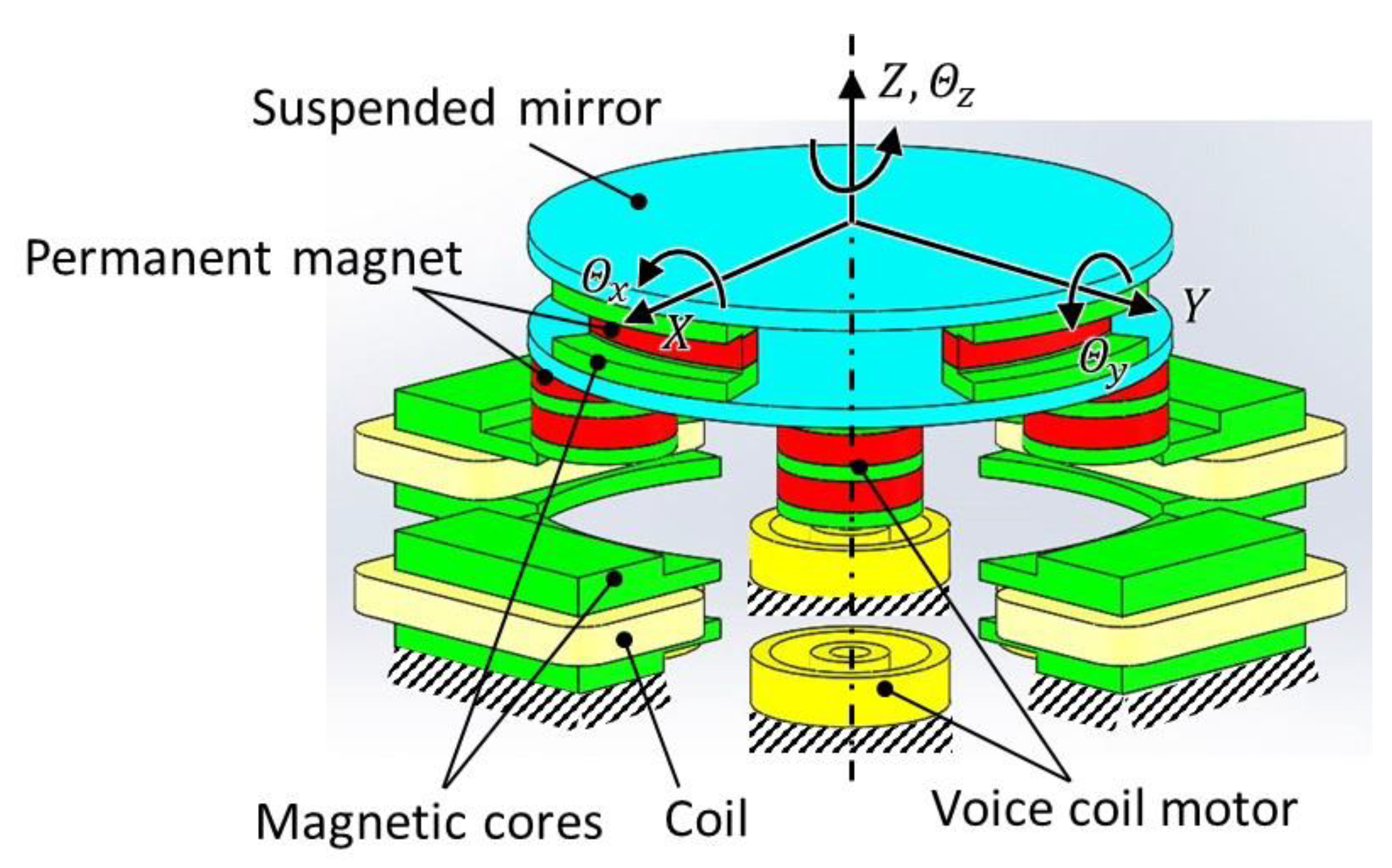
The bias magnetic flux generates magnetic couplings between the U-shaped magnets and the suspended part, as shown in
Figure 4. The magnetic couplings generate restoring torques around the X, Y, and Z axes and a restoring force in the axial direction. In the lateral directions, the current through two coils in the U-shaped iron cores facing each other provides push–pull motion needed to stabilize the suspended mirror. The magnetic suspension actively controls the two-DOF lateral movement, and passively supports the mirror for four-DOF out of plane movement.
2.3. Tip-Tilt and Axial Positioning Mechanism
Four VCMs are attached to the bottom of the suspended mirror at 90 degree intervals. These are used to position the mirror in the tip-tilt directions, as shown in
Figure 3. The VCMs can also be used for positioning of the mirror in the axial direction. The tip-tilt motion is generated by supplying push-pull currents to diametrically opposed VCMs. Axial motion is generated by supplying the same current to each VCM. The sum of the tip-tilt and axial control currents is supplied to each VCM coil in actual use.
3. Design and Fabrication of the Prototype FSM
3.1. Design of the VCM and Magnetic Suspension
The VCMs have to be compact and generate a sufficient force.
Figure 5 shows the dimensions of the designed VCM, which consists of two ring-shaped and two column-shaped magnets, an inner and an outer coil, and magnetic cores. The ring and disk cores are sandwiched between the upper and lower permanent magnets to increase the lateral magnetic flux from the permanent magnets to the coils. The inner and outer coils effectively use the lateral magnetic flux from the permanent magnets to generate an axial Lorentz force. The gap between the coil and the core was set to be large so that there would be no possible contact due to the tip-tilt motion of the mirror.
The column-shaped magnets are made of NdFeB (N45), and the ring-shaped ones are N35UH. The number of coil windings on the inside and outside is 83, respectively. The diameter of the coil wire is ϕ0.4 mm. The core material is electromagnetic soft iron (SUY). The magnets and the cores were assembled with epoxy adhesive. The shape of the high output VCM was analyzed using magnetic field analysis software (ANSYS Maxwell, Ansys). The NdFeB magnet’s residual flux density and coercive force were set to be at 1.26 T and 907 kA/m, respectively.
In the simulation, the current–force coefficient of the VCM at the center position was 1.26 N/A, which was verified by measurement, as shown in
Figure 6a. As shown in
Figure 6b, the reduction in force is about 9.9% for displacement by 1 mm, achieved by applying a current density of 5.4 A/mm
2 through the VCM coil. This reduction is acceptable for the positioning controller.
The final dimensions of the designed magnetic suspension are shown in
Figure 7. The NdFeB magnet in the rotor is N40 and the cores are made of electromagnetic soft iron (SUY). The number of turns in each magnetic suspension coil is 144, and the diameter of the coil wire is ϕ0.315 mm.
The simulated stiffness of the magnetic suspension in the tip-tilt and axial directions were 3.1 Nm/rad and 4.2 N/mm, respectively. This stiffness of the magnetic suspension was determined by considering the maximum force achieved with the designed VCMs. Simulation of the negative stiffness and current–force coefficient in the lateral direction found them to be 10.3 N/mm and 1.3 N/A, respectively.
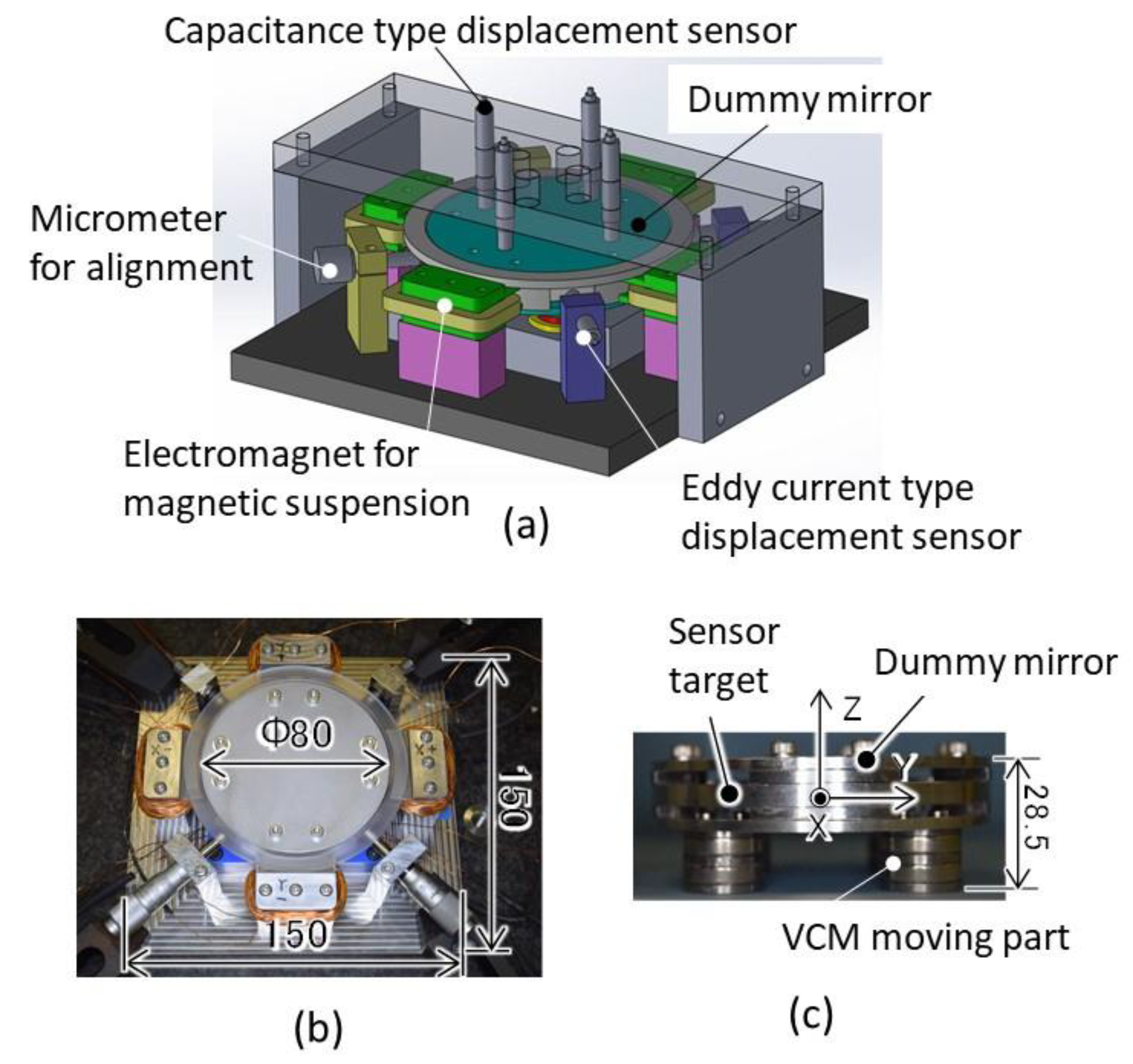
3.2. Prototype FSM
Figure 8a shows the configuration of the test rig, including the FSM, displacement sensors, and adjustment jigs (micrometers). To easily evaluate the FSM performance, the displacement sensors were tentatively placed above the dummy mirror. At the final product stage, the displacement sensors should move to the lower surface of the mirror.
Figure 8b,c show photographs of the assembled FSM without the displacement sensors and the suspended mirror. In order to simplify the fabrication and the experiment, the test mirror was made of duralumin. The diameter and mass of the dummy mirror, including parts of the magnetic suspension and the VCMs, were 80 mm and 0.22 kg, respectively. Compared to actual mirror materials such as quartz glass and beryllium, aluminum alloy for the dummy mirror has a larger specific gravity and smaller Young’s modulus, so the experimental conditions are limiting from the viewpoint of extending the bandwidth. A plastic spacer to limit the lateral movement of the dummy mirror to 0.5 mm was inserted between the mirror and the stator. The touch-up current can be reduced by limiting the air gap, and the controller gains can be set higher. Two micrometers were attached to calibrate the lateral displacement sensors.
3.3. Control System
A DSP system (DS1103, dSPACE) was used to control the motion of the mirror in the lateral, axial, and tip-tilt directions. The 16 bit AD/DA converters were used, and the sampling frequency was 20 kHz. The lateral displacement, measured by two eddy current displacement sensors (PU-05, AEC), was feedbacked to the magnetic suspension. Four capacitance type displacement sensors (C23-B, Lion Precision) precisely measure the axial displacements at 90 degree intervals at the same radius on the surface of the dummy mirror. The tip-tilt and axial displacements of the dummy mirror are calculated using the measured signals and these were feedbacked to the controller. The sensor signal noise is reduced using 2nd-order low-pass filters with a cutoff frequency of 5 kHz. PID controllers are used for the tip-tilt, axial, and lateral movement control. The control parameter values were determined experimentally to extend the servo bandwidth as much as possible and enable a stable touch-up.
The four VCMs and four electromagnets are each connected to independent voltage amplifiers (Output range: −28 to +28 V, DCV-304, Uniel-Denshi). Voltage control is applied in the lateral and axial directions. In order to increase the servo bandwidth, current feedback using current transducers (LA25-NP, LEM Corp., Tokyo, Japan) was applied to control the tip-tilt motion movement.
4. Magnetic Suspension and Positioning Test
4.1. Magnetic Suspension
Figure 9 shows the tip-tilt (
θx,
θy), axial (
z), and lateral (
x,
y) displacements of the dummy mirror at startup. Only the lateral motion was actively controlled in this test. A bias current of 0.46 A was supplied to each VCM to compensate for the weight of the dummy mirror. In all directions, the suspended dummy mirror moved from its initial position to the zero point. In the lateral directions, no overshoot was observed due to active control generating sufficient damping.
In the tip-tilt and axial directions, the vibration of the dummy mirror settled down within 0.5 s after startup at 0.5 s. This residual vibration can be suppressed in a shorter time using the VCMs. This result shows that stable suspension of the dummy mirror can be realized without VCM control. Furthermore, the smooth motion of the dummy mirror confirms that perfect non-contact suspension was realized.
4.2. Stiffness in the Tip-tilt and Axial Directions
The passive stiffness of the magnetic suspension in the tip-tilt and axial directions were identified using one-degree-of-freedom mass-spring-damper models and the frequency responses to displacements in the theses directions from the input currents to the VCMs, as shown in
Figure 10.
The natural frequencies in the
θx and
θy directions were almost the same, being at 26.0 and 25.7 Hz, respectively. The natural frequency in the axial (Z) direction was 22.0 Hz. The designed mass (0.216 kg) and the inertia moment (1.23 × 10
−4 kgm
2) of the supported part, and the measured natural frequencies were used to identify the stiffness. The identified stiffness in the tip-tilt and axial directions were 3.2–3.4 Nm/rad and 4.1 N/mm, respectively. These identified values are almost the same as the design values given in
Section 3.2.
Furthermore, no resonant frequency due to elastic vibration modes can be seen up to 2 kHz. The measured interference between the tip-tilt movement shown in the gain plots is less than −34.4 dB. The mirror system can be regarded as having a simple one-degree-of-freedom vibration system without any interference and can be easily controlled.
4.3. Stroke Test
Figure 11 shows the tip-tilt and axial motions of the dummy mirror when 1 Hz reference sine waves were input to the controller. The tip-tilt and axial strokes achieved were ±20 mrad and ±500 μm, respectively. These strokes sufficiently satisfy the design targets.
4.4. Servo Bandwidth
Figure 12a shows the closed-loop frequency responses in the tip-tilt directions. The gain and phase diagrams in both directions are similar, and it is clear that there is no difference between the dynamic characteristics in each tip-tilt direction. The servo bandwidths are 1180 Hz and 1210 Hz in the
θx and
θy directions, respectively. The design target of 1000 Hz was achieved with simple PID controllers without having to use notch filters to reduce the signals induced by higher vibration modes.
Figure 12b shows the Bode diagram for the axial direction. The system has a bandwidth of 220 Hz, which is more than sufficient for focus correction. Using the magnetic suspension, it is possible to suppress the elastic modes generated by conventional elastic guideways, and the servo bandwidth can be extended to a sufficiently high frequency with a simple control system and without complicated tuning.
4.5. Comparison with an FSM Guided by a Gimbal Mechanism
For comparison, an FSM using a gimbal mechanism and flexure pivots (5006-400, Riverhawk Corp., New Hartford, NY, USA) was designed and prototyped, as shown in
Figure 13. The mirror size (ϕ80 mm), the design and allocation of the VCMs, the controller algorithm, and the feedback displacement sensors are the same as those used for the magnetic suspension type. The parameters of the PID controller for each axis were adjusted independently to increase the bandwidth by as much as possible. The reference characteristics in the
θx and
θy directions are shown in
Figure 14. The moment of inertia in the
θx direction, including the mirror and the gimbal ring, is larger than that in the
θy direction. The servo bandwidth in the
θx direction could not be made as wide as that in the
θy direction. Furthermore, vibration modes other than the tip-tilt motion of the mirror were excited as calculated by FEM and are shown in
Figure 14b. These have an effect on the servo bandwidth. By adjusting the control parameters only, the bandwidth for the FSM with the gimbal mechanism could not reach that achieved with the magnetic suspension.
5. Conclusions
An FSM with an 80 mm diameter mirror supported by a compact and simple magnetic suspension, allowing two-DOF lateral control of the mirror, and driven by four compact VCMs, allowing control in the tip-tilt and axial directions, was proposed, fabricated, and evaluated. The mirror was a dummy mirror made of aluminum alloy. Rapid positioning of the mirror was achieved by controlling the VCMs with simple PID compensators. The VCMs, which have inner and outer coils, and use the magnetic flux from permanent magnet, were designed and tested. The driving ranges of the mirror were ±20 mrad and ±500 μm in the tip-tilt and axial directions, respectively. No large interference nor structural resonances, that would compromise the stability of the mirror, were not found. Servo bandwidths of more than 1 kHz and 200 Hz in the tip-tilt and axial directions of the mirror, respectively, were achieved. These ranges of movement and bandwidths satisfy the design targets for the mirror to be used on observation satellites.
A comparative experiment between the magnetically suspended mirror and a gimbal guided mirrors showed the FSM dynamics using the magnetic suspension to be much simpler than those for the gimbal mechanism; thus, it was possible to show that the bandwidth could be easily widened, and that the axial positioning for focus correction could be implemented.
In future work, in order to apply this method to an actual observation satellite, we need to develop a compact launch lock mechanism to withstand the vibration encountered during lunch and to have built-in displacement sensors for the FSM. Furthermore, in order to withstand long-time use in space, optimization of the material and structures, and durability and reliability tests under various conditions are necessary.
Author Contributions
Conceptualization, T.S. and K.K.; methodology, T.S. and D.S.; software, D.S.; validation, T.S. and K.F.; formal analysis, T.S. and D.S.; investigation, D.S.; resources, K.F.; data curation, D.S. and K.F.; writing—original draft preparation, T.S.; writing—review and editing, T.S.; visualization, T.S. and D.S.; supervision, T.S.; project administration, T.S.; funding acquisition, T.S. and K.K. All authors have read and agreed to the published version of the manuscript.
Funding
This research received no external funding.
Conflicts of Interest
The authors declare no conflict of interest.
References
- Inamori, T.; Wang, J.; Saisutjarit, P.; Nakasuka, S. Jitter reduction of reaction wheel by management of angular momentum using magnetic torquers in nano- and micro-satellites. Adv. Space Res. 2013, 52, 222–231. [Google Scholar] [CrossRef]
- Shimizu, T.; Nagata, S.; Tsuneta, S.; Tarbell, T.; Edwards, C.; Shine, R.; Hoffmann, C.; Thomas, E.; Sour, S.; Rehse, R.; et al. Image stabilization system for Hinode (Solar-B) Solar optical telescope. Sol. Phys. 2008, 249, 221–232. [Google Scholar] [CrossRef]
- Akeno, K.; Shimizu, D.; Shinshi, T. A fast steering mirror driven by voice coil motors and supported by a super elastic rod. In Proceedings of the 21st International Conference on Mechatronics Technology (ICMT 2017), Ho Chi Minh City, Vietnam, 20–23 October 2017. [Google Scholar]
- Asada, N.; Matsuki, H.; Minami, K.; Esashi, M. Silicon micromachined two-dimensional galvano optical scanner. IEEE Trans. Magn. 1994, 30, 4647–4649. [Google Scholar] [CrossRef]
- Loney, G.C. Design of a small-aperture steering mirror for high-bandwidth acquisition and tracking. Opt. Eng. 1990, 29, 1360–1365. [Google Scholar] [CrossRef]
- Kluk, D.J.; Boulet, M.T.; Trumper, D.L. A high-bandwidth, high-precision, two-axis steering mirror with moving iron actuator. Mechatronics 2012, 22, 257–270. [Google Scholar] [CrossRef]
- Woody, S.; Smith, S. Design and performance of a dual drive system for tip-tilt angular control of a 300 mm diameter mirror. Mechatronics 2006, 16, 389–397. [Google Scholar] [CrossRef]
- Hafez, M.; Sidler, T.C.; Salathé, R.P.; Jansen, G.L.M.; Compter, J.C. Design, simulations and experimental investigations of a compact single mirror tip/tilt laser scanner. Mechatronics 2000, 10, 741–760. [Google Scholar] [CrossRef]
- Kodeki, K.; Fukushima, K.; Inoue, M.; Kashiwase, T.; Shimizu, T.; Sakao, T.; Kano, R.; Hara, H.; Nagata, S.; Yoshida, T.; et al. Design and performance of tip-tilt mirror system for solar telescope. J. Spacecr. Rocket. 2004, 41, 868–876. [Google Scholar] [CrossRef]
- Berta, A.; Hedding, L.R.; Hoffman, C.; Messaros, M. Development of a commercial line of high-performance fast-steering mirrors. Opt. Scanning Des. Appl. 1999, 3787, 181–192. [Google Scholar]
- Ostaszewski, M.A.; Summers, R.T. High-performance reactionless scan mechanism. In Proceedings of the SPIE 1920, Albuquerque, NM, USA, 25 August 1993. [Google Scholar]
- Shinshi, T.; Shimizu, D.; Kodeki, K.; Fukushima, K. A fast steering mirror driven by voice coil motors and supported by magnetic suspension. In Proceedings of the 23rd International Conference on Mechatronics Technology (ICMT 2019), Salerno, Italy, 23–26 October 2019. [Google Scholar]
- Asama, J.; Shinshi, T.; Hoshi, H.; Takatani, S.; Shimokohbe, A. A new design for a compact centrifugal blood pump with a magnetically levitated rotor. ASAIO J. 2004, 50, 550–556. [Google Scholar] [CrossRef] [PubMed]
Figure 1.
An observation satellite with a fast steering mirror disturbed by reaction wheels.
Figure 1.
An observation satellite with a fast steering mirror disturbed by reaction wheels.
Figure 2.
A fast steering mirror (FSM) having a multi-degree-of-freedom (DOF) mechanism. The rotational motion is for jitter compensation. The translational motion is for defocus correction.
Figure 2.
A fast steering mirror (FSM) having a multi-degree-of-freedom (DOF) mechanism. The rotational motion is for jitter compensation. The translational motion is for defocus correction.
Figure 3.
Configuration of an FSM in which the mirror is supported by a two-DOF controlled magnetic suspension and driven by voice coil motors (VCMs).
Figure 3.
Configuration of an FSM in which the mirror is supported by a two-DOF controlled magnetic suspension and driven by voice coil motors (VCMs).
Figure 4.
The proposed magnetic suspension mechanism. The lateral movement is controlled by electromagnets. The other motion is supported by the magnetic coupling.
Figure 4.
The proposed magnetic suspension mechanism. The lateral movement is controlled by electromagnets. The other motion is supported by the magnetic coupling.
Figure 5.
The design and dimensions of the VCM. The inner and outer coils effectively use the lateral magnetic flux from the permanent rings.
Figure 5.
The design and dimensions of the VCM. The inner and outer coils effectively use the lateral magnetic flux from the permanent rings.
Figure 6.
The VCM characteristics: (a) Measured current–force relationship of the designed VCM; (b) measured and simulated force at each position with a current density of 5.4 mm2/A in the VCM coil.
Figure 6.
The VCM characteristics: (a) Measured current–force relationship of the designed VCM; (b) measured and simulated force at each position with a current density of 5.4 mm2/A in the VCM coil.
Figure 7.
The design and the dimensions of the magnetic suspension mechanism.
Figure 7.
The design and the dimensions of the magnetic suspension mechanism.
Figure 8.
The test rig using the magnetic suspension mechanism: (a) The configuration of the test rig; (b) top view of the test rig without the displacement sensors; (c) side view of the suspended part including the dummy mirror.
Figure 8.
The test rig using the magnetic suspension mechanism: (a) The configuration of the test rig; (b) top view of the test rig without the displacement sensors; (c) side view of the suspended part including the dummy mirror.
Figure 9.
Startup response of the FSM using the magnetic suspension: (a) Translation in the X, Y, and Z directions; (b) inclination in the tip-tilt (θx and θy) directions.
Figure 9.
Startup response of the FSM using the magnetic suspension: (a) Translation in the X, Y, and Z directions; (b) inclination in the tip-tilt (θx and θy) directions.
Figure 10.
Frequency responses of the FSM using the magnetic suspension: (a) Bode plot from the VCM input current (Ix) for θx and θy; (b) Bode plot from the VCM input current (Iz) for z.
Figure 10.
Frequency responses of the FSM using the magnetic suspension: (a) Bode plot from the VCM input current (Ix) for θx and θy; (b) Bode plot from the VCM input current (Iz) for z.
Figure 11.
Long stroke positioning of the FSM with the magnetic suspension: (a) Inclination in the θx direction; (b) inclination in the θy; (c) displacement in the Z direction.
Figure 11.
Long stroke positioning of the FSM with the magnetic suspension: (a) Inclination in the θx direction; (b) inclination in the θy; (c) displacement in the Z direction.
Figure 12.
Reference characteristics of the FSM with the magnetic suspension; (a) Bode plot for the θx and θy directions; (b) Bode plot for the Z direction.
Figure 12.
Reference characteristics of the FSM with the magnetic suspension; (a) Bode plot for the θx and θy directions; (b) Bode plot for the Z direction.
Figure 13.
The test rig using a gimbal ring and flexural pivots: (a) Configuration of the gimbal mechanism; (b) configuration of the test rig; (c) photograph of the test rig.
Figure 13.
The test rig using a gimbal ring and flexural pivots: (a) Configuration of the gimbal mechanism; (b) configuration of the test rig; (c) photograph of the test rig.
Figure 14.
Reference characteristic of the FSM using gimbal mechanism: (a) Bode plots in the θx and θy directions; (b) simulated vibration modes near the peak frequencies.
Figure 14.
Reference characteristic of the FSM using gimbal mechanism: (a) Bode plots in the θx and θy directions; (b) simulated vibration modes near the peak frequencies.
| Publisher’s Note: MDPI stays neutral with regard to jurisdictional claims in published maps and institutional affiliations. |
© 2020 by the authors. Licensee MDPI, Basel, Switzerland. This article is an open access article distributed under the terms and conditions of the Creative Commons Attribution (CC BY) license (http://creativecommons.org/licenses/by/4.0/).
