Article

A General Double Vector-Based Model Predictive Current Control for the Dual Three-Phase Motors

Department of Electrical Engineering, University of Shanghai for Science and Technology, Shanghai 200093, China
*
Author to whom correspondence should be addressed.
Electronics 2020, 9(12), 2000; https://doi.org/10.3390/electronics9122000
Submission received: 19 October 2020 / Revised: 19 November 2020 / Accepted: 23 November 2020 / Published: 25 November 2020
(This article belongs to the Section Power Electronics)

Abstract

:
Traditional model predictive current control (MPCC) for motors can only choose one optimal voltage vector during one control period, which creates problems of over-regulation or under-regulation for the current tracking. With zero vectors being injected in the chosen optimal voltage vector, the traditional MPCC can obtain better performance, which is called duty cycle MPCC. However, whether the traditional or the duty cycle MPCC is being applied to multiphase motors, it is more difficult for the phase to increase. In this paper, a general double vector-based MPCC mechanism has been studied for a dual three-phase permanent synchronous motor (PMSM) with dual Y shift 30° windings used in aerospace propulsion. Firstly, the choosing range of the second voltage vector in duty cycle MPCC was extended to an arbitrary vector; then, the cost function was rationally designed, and the delay compensation was added to improve the control performance as well. Compared with the traditional or duty cycle MPCC, this general double vector-based MPCC has better torque performance and fewer total harmonic distortions in the full speed range and under different load conditions.

1. Introduction

Three-phase permanent synchronous motors (PMSMs) have broad applications in many fields because of their advantages of high efficiency and high power factor [1]. As a further development, multiphase PMSMs can be better applied to high-power situations such as aerospace, electric vehicle, ship propulsion, and wind power generation, which usually need high reliability [2,3]. In general, the control strategies of multiphase PMSMs are similar to those of the normal three-phase PMSMs, although it would be more difficult as the number of phases increases. There are three kinds of common control strategies: vector control (VC), direct torque control (DTC), and model predictive control (MPC). For the VC method, it has a nice control performance; however, its applicability would be hindered due to its complex coordinate transformation when it is used for the multiphase motors [4]. The DTC strategy has a good dynamic response performance, but the torque ripple and inaccuracy of flux linkage observation are the main factors limiting its application, and this strategy has been rarely used in multiphase motors [5]. Considering the disadvantages of VC and DTC strategies, the MPC method has been widely used in motor control for its fast response and great adaptation to multivariable and non-linear systems in recent years [6,7].
Current control is the key to the high performance of the whole motor system, and finite control set model predictive current control (FCS-MPCC) is the main method [8,9,10,11,12,13]. In [8,9], normal FCS-MPCC has been used for a PMSM that realized an improvement of the dynamic performance of the stator current. However, this normal predictive current control chose only one voltage vector as the optimal one, which could cause large torque fluctuation. In order to improve the design, some double vector-based MPCC have been researched, e.g., a duty cycle MPCC was proposed in [10,11,12], with the utilization of zero vectors, the output optimal voltage vector was reconstructed, and several improvements have been given in [13] to realize a better match between the chosen voltage vector by MPCC and the zero vectors.
To make the extension of the double vector-based MPCC mentioned above, an arbitrary vector was used to replace to zero vectors to form a general double vector-based MPCC [14], based on which the output optimal voltage could provide both adjustable amplitude and adjustable direction, which resulted in better control performance. In [15], the prominent advantages of a double vector-based MPCC was verified by analyzing the accuracy and range of voltage vector selection. As an extension, three vector-based MPCC with low-complexity was proposed in [16], which could optimize the control performance; however, the control difficulty was increased, and it was not suitable for multiphase PMSMs.
Both traditional and improved MPCC strategies are mostly used for the three-phase motors, while for multiphase motors, only the traditional MPCC method has been widely used with the consideration of the control complexity [17,18,19,20,21,22,23,24,25]. In [17,18], the MPCC algorithm was applied to the fault-tolerant control of a five-phase motor, and the applications for six-phase motors also have been investigated in [19,20,21,22,23,24,25]. In [25], a MPCC method involving the current harmonics suppression has been proposed. Nevertheless, there are few research studies on applications of double vector-based or multiple vector-based MPCC applied for multiphase motors.
On the other hand, when the MPCC method was used for the motor control, the control performance could be influenced by the parameter uncertainties, computation requirements, and the weighting factor design for multi-objective control [11,26,27,28,29,30,31,32,33]. In [11], a delay compensation strategy was studied to improve the performance of MPCC. In [26], the weighting factor was designed and optimized by the torque deviation, while it was only suitable for low-speed situations. The design of weighting factors in [27] depended on the priority of the control variables. To ensure a relatively nice control performance, a multi-step MPCC strategy was proposed in [28], in which both the optimized and sub-optimized voltage vectors were sent to the next rolling optimization prediction to select the final optimized voltage vector. Similarly, the voltage vector was selected in various ways in order to reduce the harmonic component of a six-phase motor in [29,30,31,32]. In [33], Heun’s method was employed to obtain discrete state-space models, which achieved higher accuracy than the first-order Euler method.
In this paper, a dual three-phase permanent synchronous motor (PMSM) with dual Y shift 30° windings has been presented as the research object. A novel general double vector-based MPCC strategy was proposed; by taking advantage of the arbitrary vectors, the optimized voltage vector from a normal MPCC can be extended to a combination of two suitable voltage vectors, based on which the cost function has been rationally designed and the delay compensation has also been added to improve the control performance. The innovations include the arbitrary vector selection, cost function design, delay compensation, and the application to the dual three-phase motor, which is meaningful to popularize the MPCC method in the multiphase motors’ control.
This study is organized into six sections. Following the introduction, the discrete models of the studied dual three-phase PMSM are established in Section 2. In Section 3, the normal and duty cycle MPCC strategies are given, and the general double vector-based MPCC has been introduced in detail in Section 4. The comparisons of different methods are presented in Section 5. Finally, some conclusions are drawn in Section 6.

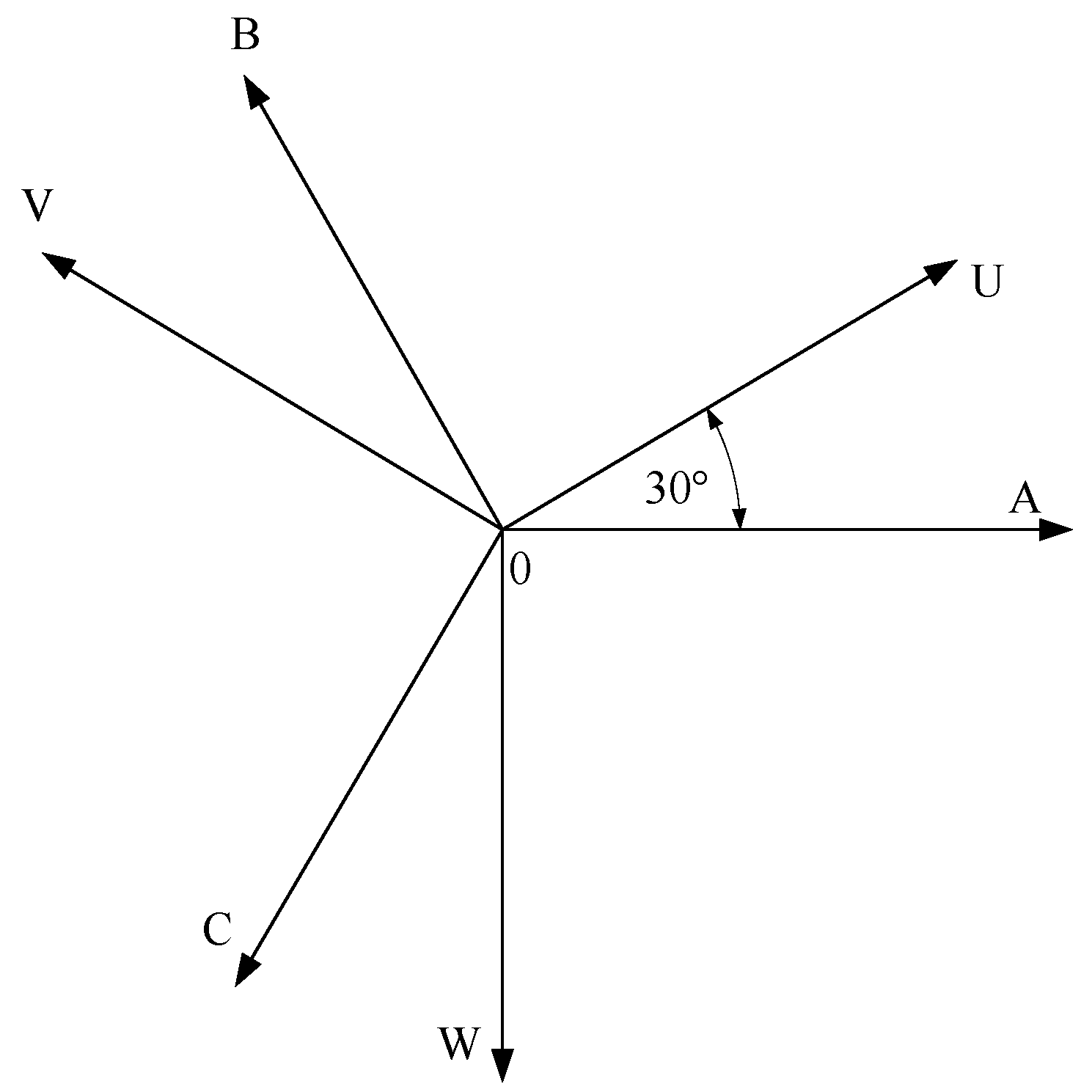
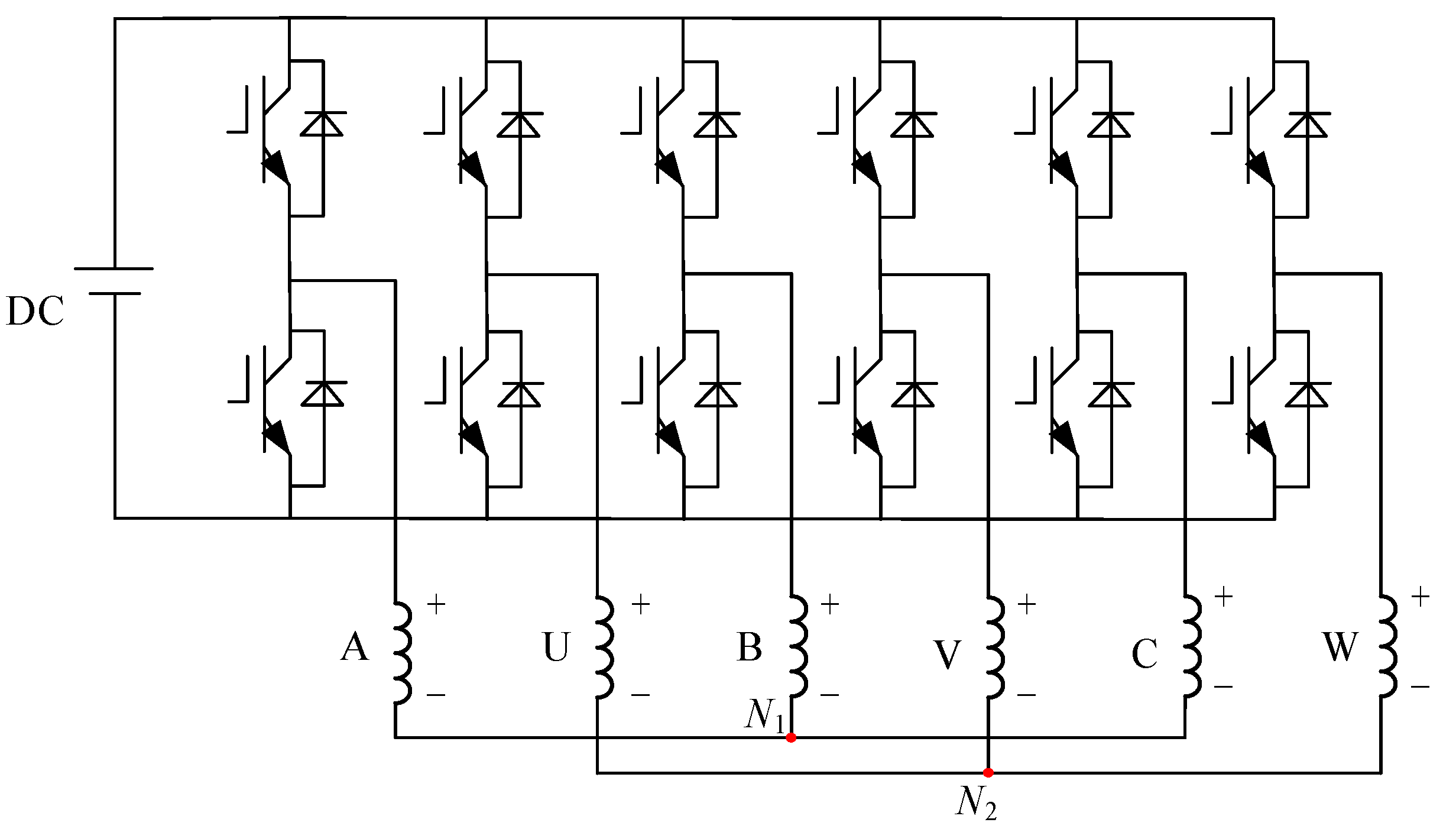
2. Discrete Mathematical Models of Dual Three-Phase PMSM

The space distribution of the stator windings for the dual three-phase PMSM with dual Y shift 30° windings studied in this paper is shown in Figure 1, in which ABC are the first set of three-phase stator windings and UVW are the other set of three-phase stator windings, and the electrical angle between the two sets of windings is 30°. The structure of the corresponding driving inverter is shown in Figure 2, which has two isolated neutral points N1 and N2.
Considering the disadvantage that double dq coordinate transformation can not realize a completely decoupling, the vector space decomposition (VSD) method is used here to map the mathematical models. The variables of dual three-phase PMSM are mapped to three orthogonal subspaces by VSD transformation, which are α-β, x-y, and o1-o2. The fundamental components and harmonics with orders 12k ± 1(k = 1, 2, 3, …) are mapped into the α-β subspace, which take participation in electromechanical energy conversion. Harmonics with orders 6k ± 1(k = 1, 3, 5, …) are mapped into the x-y subspace, which do not contribute to energy conversion. Harmonics with orders 6k ± 3(k = 1, 3, 5, …) are mapped into the o1-o2 subspace and are not considered because of the two isolated neutral points N1 and N2 [34].
Without the consideration of zero-sequence components, the voltage equations (including fundamental and harmonic components) in the dq and xy coordinates can be written as [25]
u d = R s i d   +   L d d i d d t     ω re L q i q
u q = R s i q   +   L q d i q d t + ω re L d i d + ω re ψ f
u x = R s i x   +   L z d i x d t
u y = R s i y +   L z d i y d t
where, ud, uq, ux, and uy are the voltage components in dq and xy coordinates respectively, while id, iq, ix, and iy are the corresponding current components; Ld and Lq are the inductances in dq coordinates and Lz is the leakage inductance; Rs is stator resistance; ωre is rotor electric angular velocity; ψf is permanent magnet flux. As for a surface-mounted PMSM, Ld = Lq = L for easy derivation.
Taking current components id and iq as the state variables, Equations (1) and (2) are rewritten as
d i d d t = 1 L ( u d R s i d   +   ω re L i q )
d i q d t = 1 L ( u q R s i q ω re L i d ω re ψ f ) .
After the discretization, Equations (5) and (6) are changed as
i d ( k + 1 ) = i d ( k ) + T s L [ u d ( k ) R s i d ( k ) + E d ( k ) ]
i q ( k + 1 ) = i q ( k ) + T s L [ u q ( k ) R s i q ( k )   +   E q ( k ) ]
in which Ts represents the sampling period, and k is the sampling time.
Ed(k) and Eq(k) in the above equations are the back EMF variables in dq coordinates, which could be expressed as
E d ( k ) = ω re ( k ) L i q ( k )
E q ( k ) = ω re ( k ) L i d ( k ) ω re ( k ) ψ f .
With Equations (7) and (8), the (k + 1) th current components could be predicted with the values at kth and the inverter’s output voltages.

3. Traditional and Duty Cycle MPCC Strategies

3.1. Traditional MPCC

For the inverter shown in Figure 2, there are 26 = 64 different voltage vectors being within the rolling calculations to get the optimized vector. The cost function designed for the traditional MPCC could be expressed as
g i = | i d * i d ( k + 1 ) | + | i q * i q ( k + 1 ) |
where i d * and i q * are the given current components and the control frame of this traditional MPCC is displayed in Figure 3.
Obviously, only one optimal voltage vector would be chosen as the output voltage, so it could also be called a single vector MPCC strategy (SV-MPCC), and the schematic diagram of the vector selection is shown in Figure 4.

3.2. Duty Cycle MPCC

Compared with SV-MPCC, it introduces zero voltage vectors into the chosen optimal vector to form a new voltage vector with adjustable amplitude and fixed direction. Normally, the action time of the chosen optimal vector and the zero vector could be obtained by [15]
i q ( k + 1 ) = i q ( k ) + s opt t opt + s 0 ( T s t opt ) = i q *
where topt is the action time of the chosen optimal voltage, sopt is the changing rate of iq, and s0 is the changing rate of iq when the zero voltage vector acts.
According to Equations (5) and (6), sopt and s0 could be obtained as
s 0 = 1 L ( R s i q ω re L i d ω re ψ f )
s opt = s 0 + u q _ opt L
in which uq_opt represents the optimal voltage component in the q coordinate.
With Equations (12)–(14), the duty cycle of the chosen optimal voltage vector could be solved as
γ opt = t opt T s = i q * i q ( k ) s 0 T s T s ( s opt s 0 ) .
Being different from SV-MPCC, the action time of the chosen optimal voltage vector is γTs and the corresponding schematic diagram of the vector selection is shown in Figure 5.
However, there are also some disadvantages, e.g., if the chosen optimal voltage vector is V3, the current tracking error still could not be improved even if the duty cycle is 1, which means this duty cycle MPCC could only make an improvement to some extent.

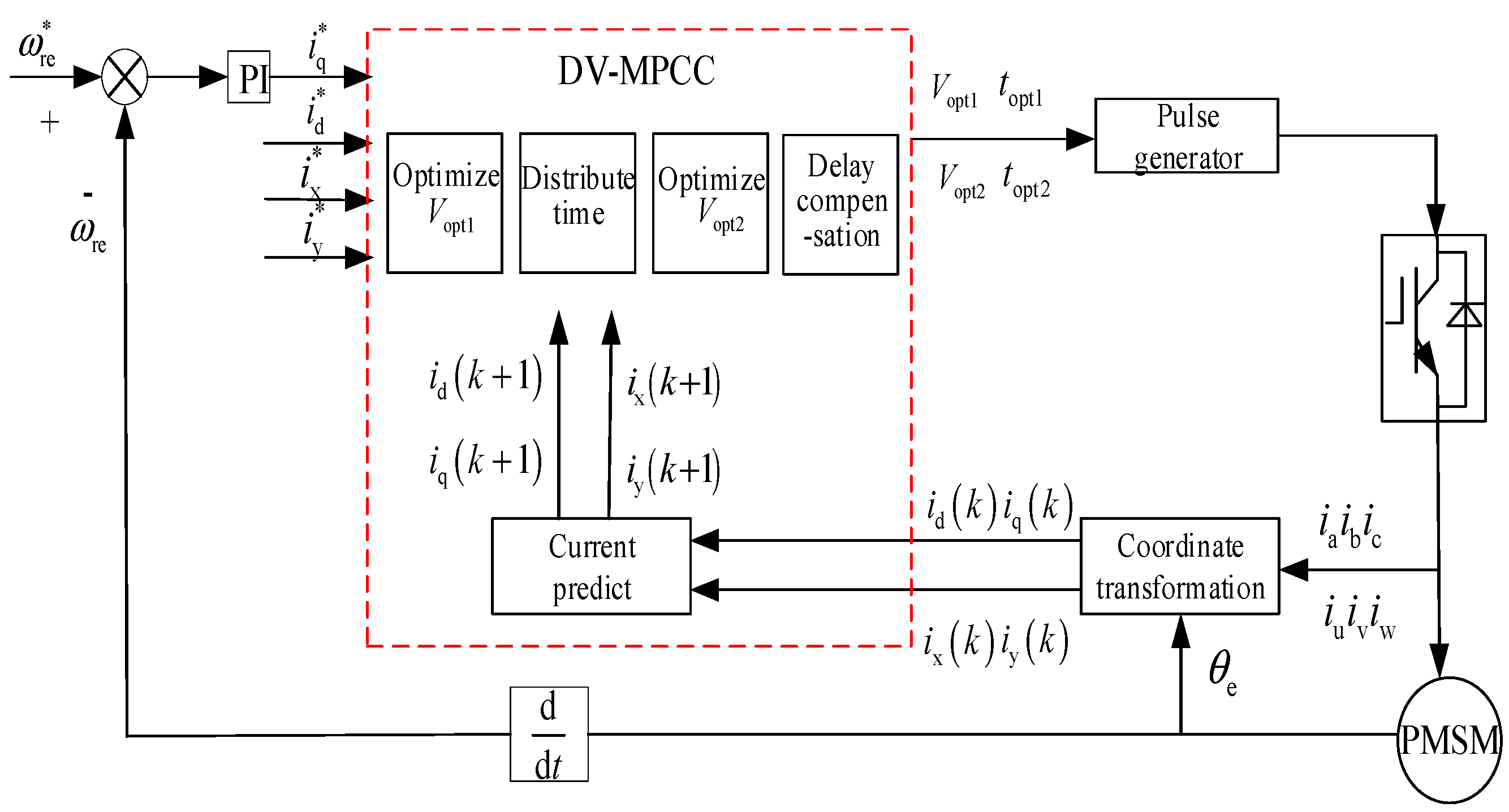
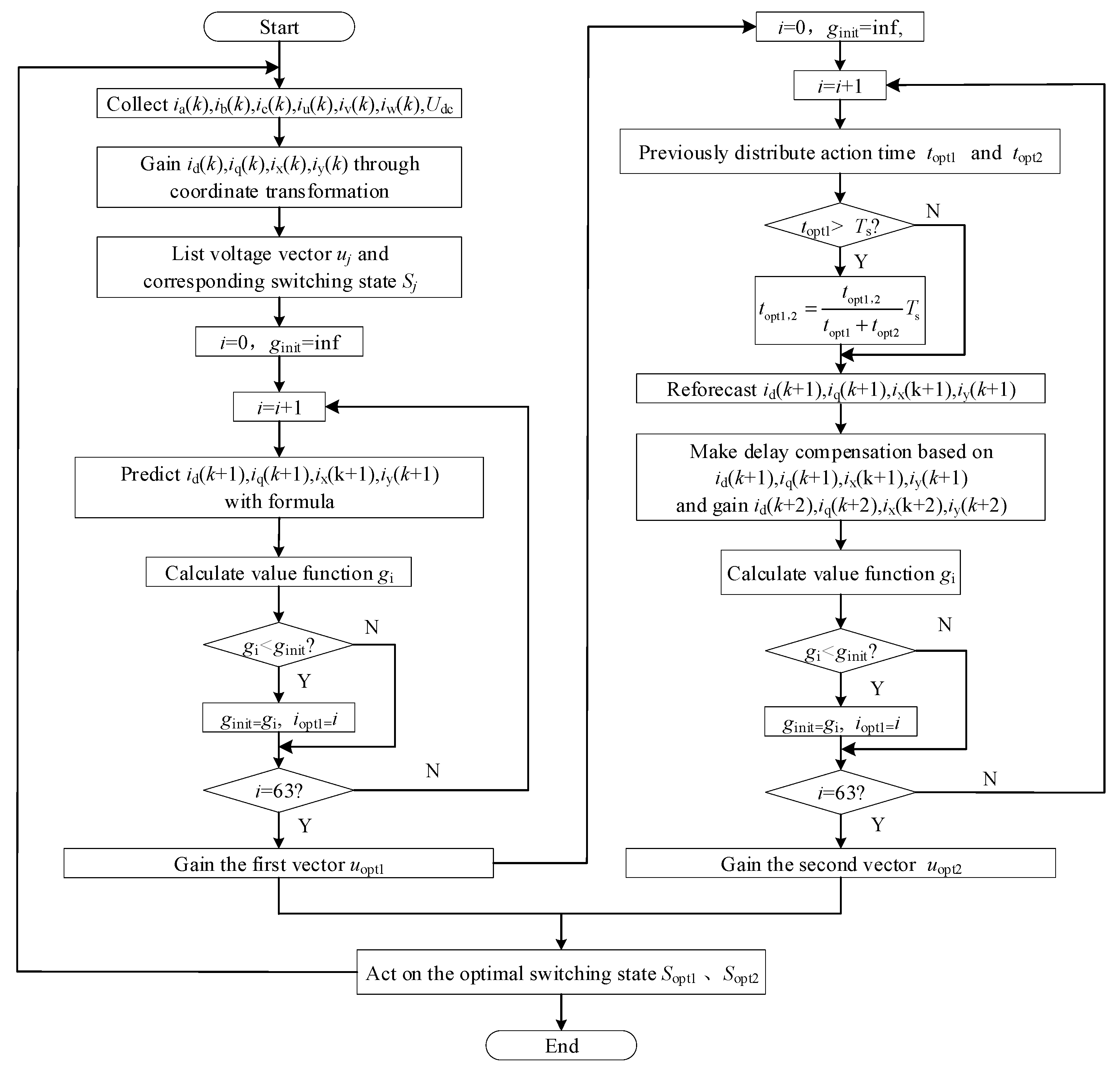
4. General Double Vector-Based MPCC Strategy

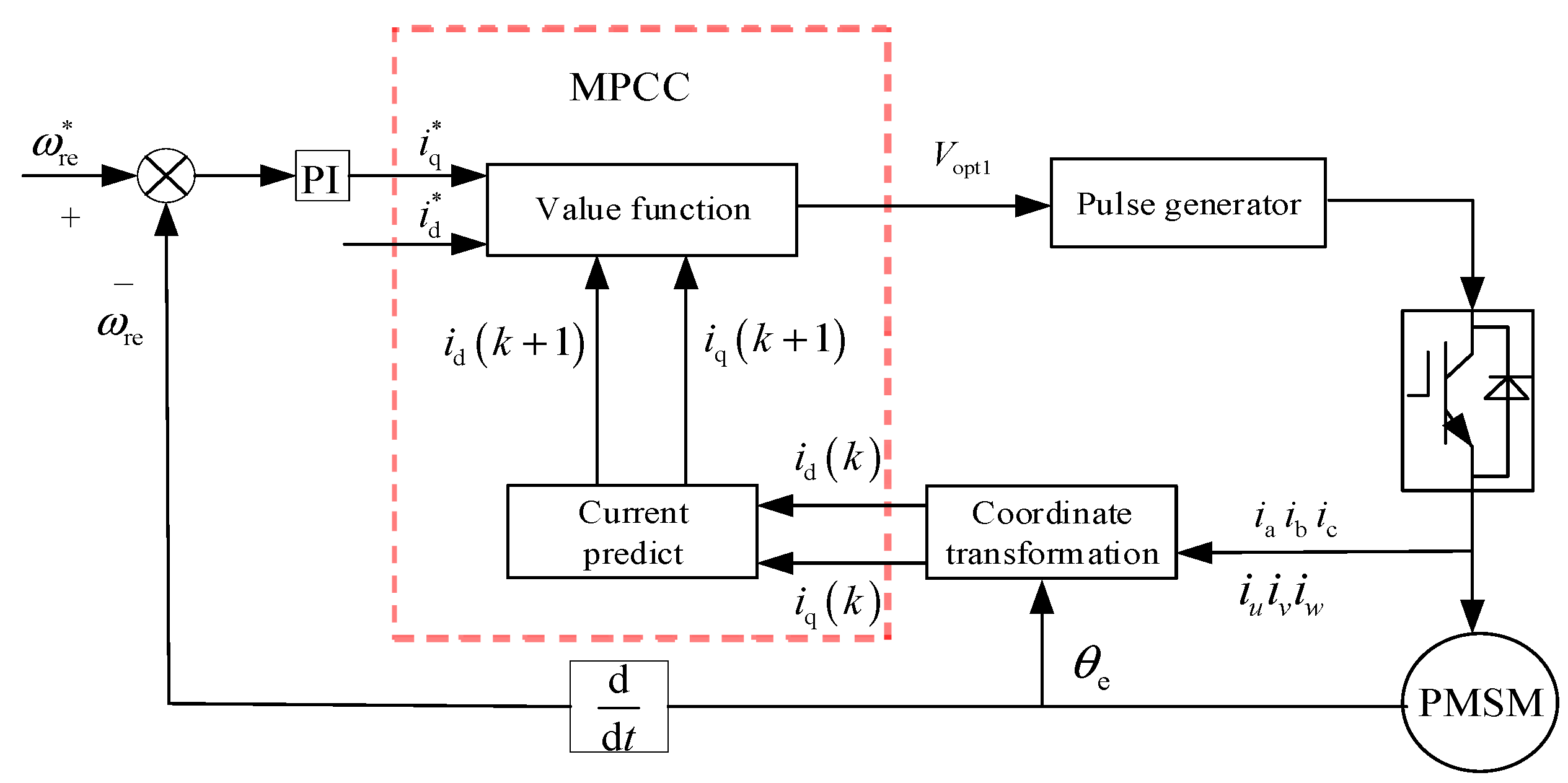
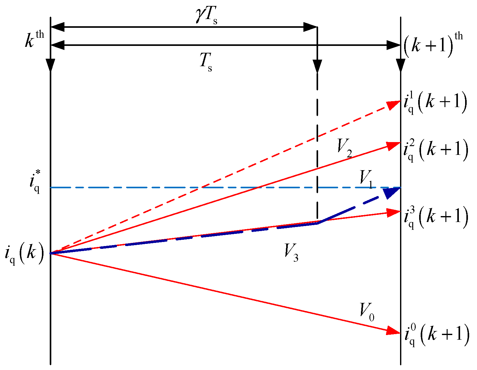
4.1. Control Principle

In order to solve the problems mentioned above, a general double vector-based MPCC (DV-MPCC) strategy has been studied for this dual three-phase PMSM. In particular, the added zero voltage vector for duty cycle MPCC extends to an arbitrary one; for example, if the chosen optimal voltage vector from SV-MPCC is V3, then vector V1 could be added to form a new output, as shown in Figure 6.
With the arbitrary voltage vector, the chosen optimal vector could be extended to a new output voltage with adjustable amplitude and adjustable direction.

4.2. Distribution of Action Time

For the action time distributions of above two vectors, firstly, assuming two pre-assigned values topt1 and Ts-topt1 for the chosen optimal voltage vector uopt1 and the added arbitrary vector uj, then the ud(k) and uq(k) in Equations (7) and (8) are readjusted as
u d = t opt 1 u d _ opt 1 + ( T s t opt 1 ) u d j
u q = t opt 1 u q _ opt 1 + ( T s t opt 1 ) u q j
where ud_opt1 and uq_opt1 are the components of the chosen optimal voltage vector in dq coordinates; udj and uqj are the components of the selected arbitrary voltage vector uj in dq coordinates, j = 1, 2, …, 64.
Similarly, the action time topt1 could be calculated by Equation (18) referring to Equation (12).
i q ( k + 1 ) = i q ( k ) + s opt 1 t opt 1 + s j ( T s t opt 1 ) = i q *
Then,
t opt 1 = i q * i q ( k ) s j T s s opt 1 s j
where, sopt1 and sj are the slopes of iq when uopt1 and uj works respectively, and
s opt 1 = s 0 + u q _ opt 1 L
s j = s 0 + u q j L .
In order to avoid the “over-modulation” phenomenon, redefining the action time of uj as topt2, then
i q * = i q ( k ) + s opt 1 ( T s t opt 2 ) + s j t opt 2 .
From Equation (22),
t opt 2 = i q * i q ( k ) s opt 1 T s s j s opt 1 .
The final action time of the uopt1 and uj are
t opt 1 = t opt 1 t opt 1 + t opt 2 T s
t opt 2 = t opt 2 t opt 1 + t opt 2 T s .

4.3. Cost Function Design

To achieve better control performance, both the fundamental components in dq coordinates and the harmonic components in xy coordinates have been taken into account. The discrete mathematical models in xy coordinates could be expressed as
i x ( k + 1 ) = ( 1 T s R s L z ) i x ( k ) + T s L z u x ( k )
i y ( k + 1 ) = ( 1 T s R s L z ) i y ( k ) + T s L z u y ( k ) .
The cost function of this DV-MPCC is designed as shown in Equation (28), which introduces additional current suppression in the harmonic plane with the comparison with the cost function of SV-MPCC (as shown in Equation (11)).
g = λ 1 | i d * i d ( k + 1 ) | + λ 2 | i q * i q ( k + 1 ) | + λ 3 ( | i x * i x ( k + 1 ) | + | i y * i y ( k + 1 ) | )
where i x * and i y * are the given current components in xy coordinates. λ1, λ2, and λ3 are the weighting factors, which are designed according to the literature [35], λ2 > λ1, and λ3 is smaller than λ1 and λ2 because of its lower priority.

4.4. Delay Compensation

For the inherent time delay problem of MPCC, there is a simple compensation with one step forward prediction. In practical applications, the current prediction value at the k + 1 sampling time is used as the sampling value for the next cycle of current prediction calculations, and i (k + 2) is substituted into the value function for optimization.
Overall, the control frame of this DV-MPCC is shown in Figure 7, and implementation flow chart is shown in Figure 8.

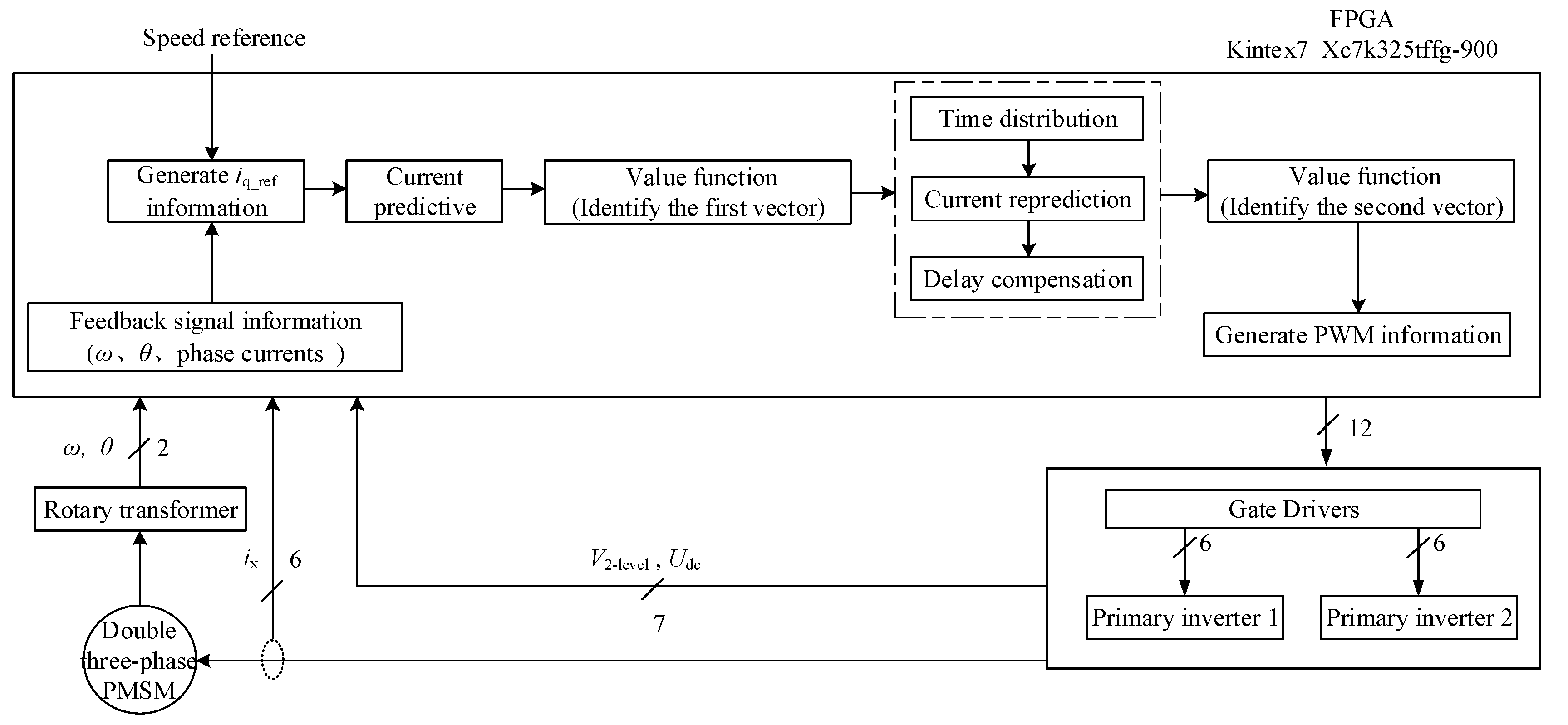
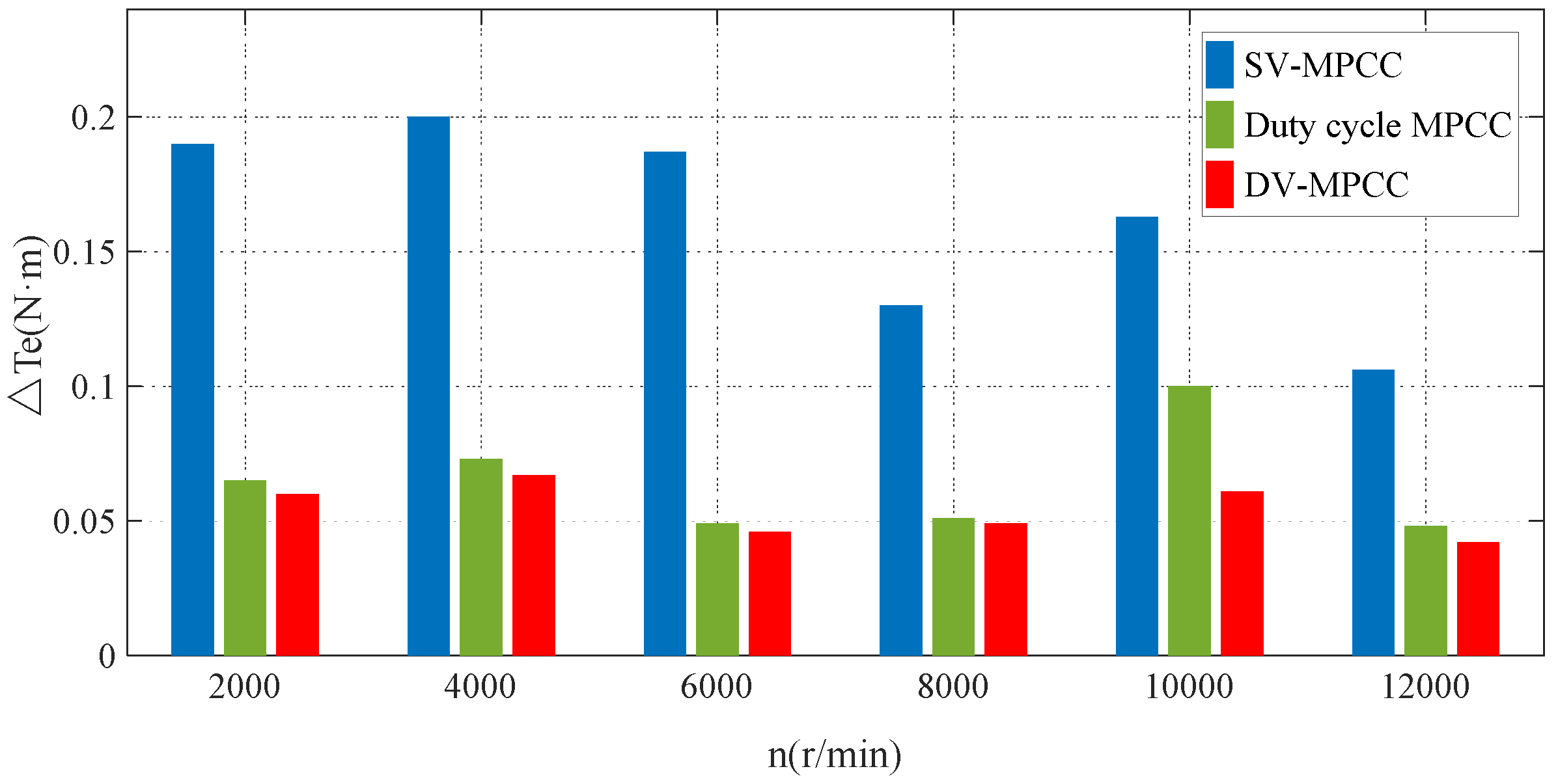
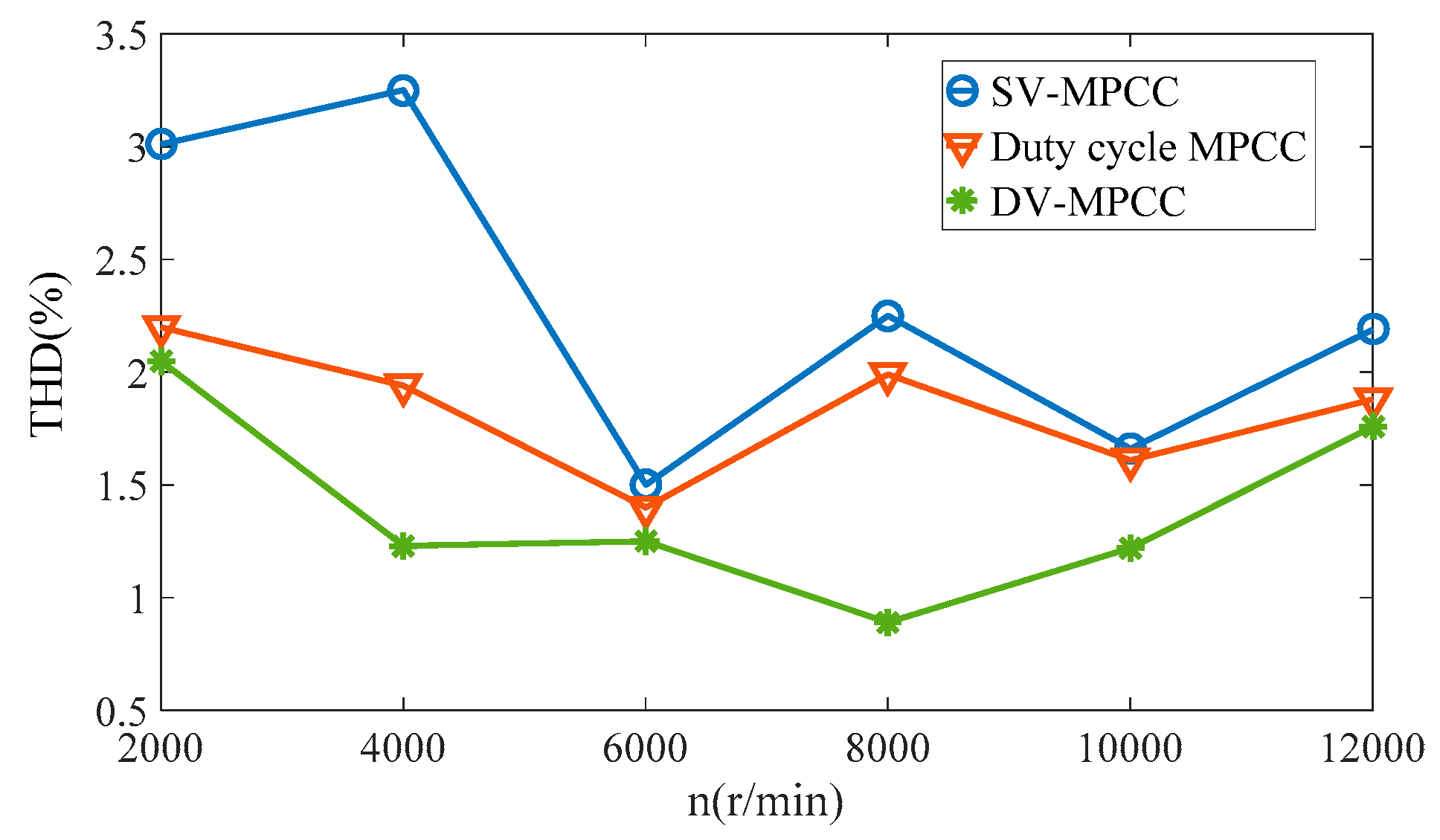
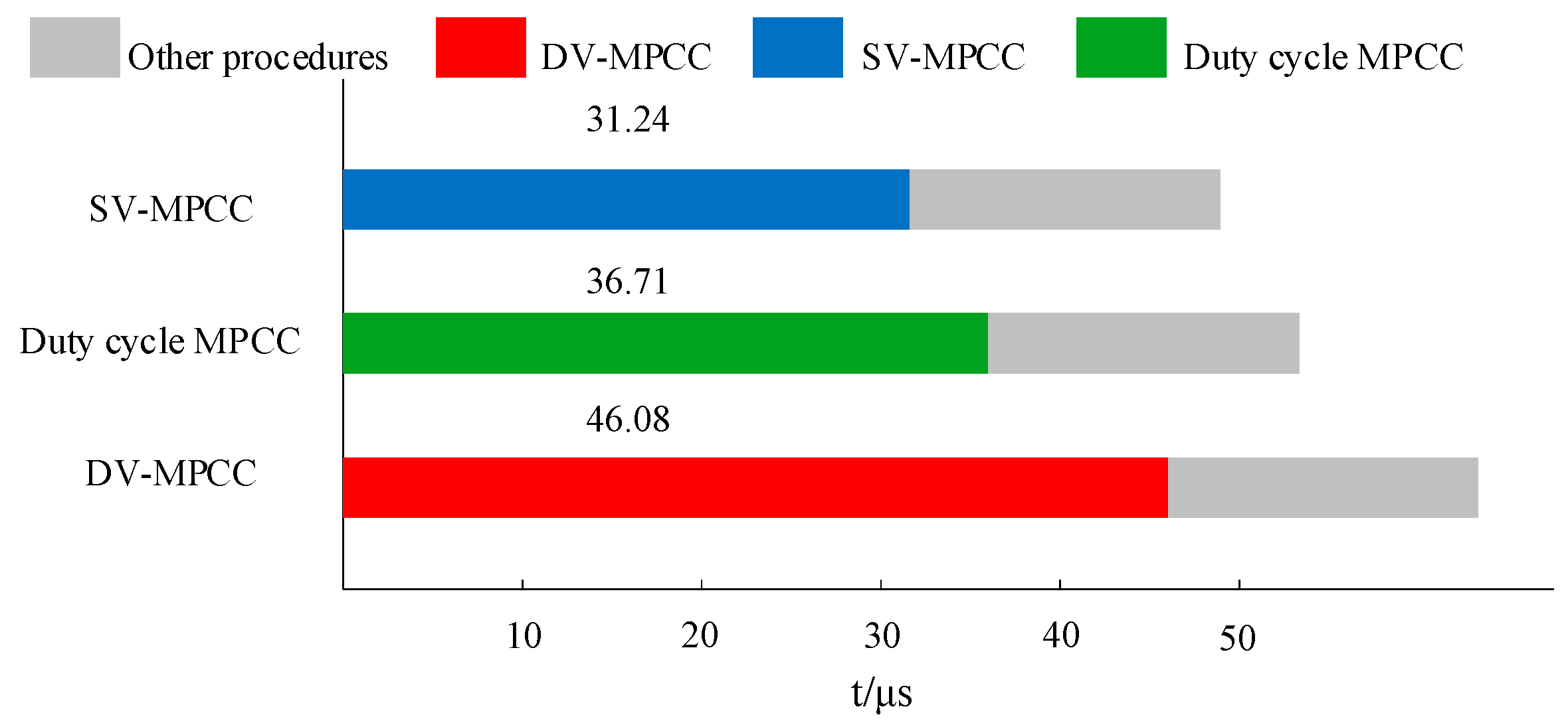
5. Experimental Results

The experimental platform is established to make verifications of this studied DV-MPCC strategy and comparisons with SV-MPCC and duty cycle MPCC methods; the block diagram of the experimental setup is shown in Figure 9. The FPGA Kintex7 Xc7k325tffg-900 platform is used for the hardware implementation of the proposed scheme. BSM50GB120DLC half-bridge modules are used in the experiment to realize inverter switches. The stator currents and speed are obtained with hall-effect sensors (CS040GT) and a Rotary Transformer (AD2S1210), respectively. Notice that the same sampling frequency of 10 kHz is used for comparison purposes. The average switching frequency is 6.5 kHz when λ1 = 0.25, λ2 = 0.45, and λ3 = 0.15. The values of λ1, λ2, and λ3 remain unchanged during all tests. The tested dual three-phase PMSM is a 2.5 kW dual three-phase PMSM. The detailed parameters are listed in Table 1.
Here, the torque and current responses under different operation conditions have been used for verification and comparisons.
The electromagnetic torque equation of dual three-phase motor can be simplified as
T e = 3 P n i q [ i d ( L d L q ) + ψ f ] = 3 P n i q ψ f .
When the motor starts and reaches the rated speed of 12,000 rpm without load, the torque responses with different control strategies are compared in Figure 10.
It can be seen that the torque ripple of DV-MPCC is lower than that of the other two control strategies, and it is the most steady one. In order to make quantitative comparisons, a torque ripple evaluation value has been defined as Equation (30); in detail, N is the amount of the sampled data, while Te_ave represents the average torque.
Δ T e = ( 1 N n = 1 N ( T e ( n ) T e _ ave ) )
When a 3 N∙m load is added at t = 0.05 s, the corresponding torque responses are shown in Figure 10, which reflects the same conclusions. The highlight of Figure 10 shows that a rapid response can be gained under any of the three strategies when loaded, and the rise time is about 0.00025 s; no obvious difference exists.
The quantitative comparison results are listed in Table 2, which also shows the superiority of the DV-MPCC method.
The steady waveforms of dual three-phase stator currents and the corresponding total harmonic distortions (THD, which is defined as Equation (31)) are shown in Figure 11.
THD = n = 2 H ( G n G 1 ) 2
where Gn and G1 are the effective values of all harmonic components and fundamental components, respectively.
When the SV-MPCC control algorithm is adopted, the THD is 3.01%, while it is 2.20% for duty cycle MPCC and 2.05% for DV-MPCC.
To have a further verification in the all-speed range, different experiments have been carried out at 2000, 4000, 6000, 8000, 10,000, and 12,000 rpm; the quantitative comparisons of torque ripple are shown in Figure 12, and the THD comparisons are shown in Figure 13.
Taking the speed of 10,000 rpm as an example, the torque ripple of DV-MPCC is respectively reduced by 60.4% and 12.5% compared with SV-MPCC and duty cycle MPCC. The THD performance of DV-MPCC is superior to the other strategies in the full speed range.
In addition, the operation execution times of the three strategies are compared in Figure 14. The results show that the implementation time of this proposed method has not increased too much, which is feasible to the digital implementation.

6. Conclusions

For a dual three-phase permanent synchronous motor (PMSM) with dual Y shift 30° windings, a general double vector-based MPCC method has been studied in detail to improve the control performance. Firstly, the traditional SV-MPCC and duty cycle MPCC are analyzed, and the zero voltage vector is extended to an arbitrary vector to form the DV-MPCC strategy. Then, the specific design processes, including action time design, cost function design, and the time delay compensation, have been given. Finally, validation and comparison experiments have been carried out under different operation conditions, which show that compared with the traditional or duty cycle MPCC, this DV-MPCC has better torque ripple and total harmonic distortion performance in the full speed range and under different load conditions.

Author Contributions

Conceptualization, Q.Y. and Y.Y.; methodology, T.M. and Y.Y.; software, T.M. and R.Z.; validation, Q.Y., T.M. and Y.Y.; formal analysis, Q.Y. and T.M.; investigation, Q.Y.; resources, T.M.; data curation, T.M.; writing—original draft preparation, T.M. and R.Z.; writing—review and editing, R.Z.; visualization, T.M.; supervision, Q.Y.; project administration, Q.Y.; funding acquisition, Q.Y. All authors have read and agreed to the published version of the manuscript.

Funding

This research was funded by Shanghai Sailing Program, CN, grant number 18YF1418300.

Acknowledgments

This work was supported by Shanghai Sailing Program (grant no.18YF1418300).

Conflicts of Interest

The authors declare no conflict of interest.

References

  1. Ho Pham, H.A.; Pham, Q.K.; Cao, V.K. Advanced PMSM machine parameter identification using modified Jaya algorithm. In Proceedings of the 2019 International Conference on System Science and Engineering (ICSSE), Dong Hoi City, Vietnam, 19–21 July 2019; pp. 445–450. [Google Scholar] [CrossRef]
  2. Fernando, B.; Jesus, D.; Alejandro, G.Y.; Oscar, L.; Diego, P. Control strategy for multiphase drives with minimum losses in the full torque operation range under single open-phase fault. IEEE Trans. Power Electron. 2017, 32, 6275–6285. [Google Scholar] [CrossRef]
  3. Yu, B.; Song, W.; Tang, T.; Wang, S.; Yang, P. A finite control set model predictive current control scheme for five-phase PMSMs based on optimized duty ratio. In Proceedings of the 2019 IEEE Applied Power Electronics Conference and Exposition (APEC), Anaheim, CA, USA, 17–21 March 2019; pp. 2564–2569. [Google Scholar] [CrossRef]
  4. Kamel, T.; Abdelkader, D.; Said, B. Vector control of five-phase permanent magnet synchronous motor drive. In Proceedings of the 4th International Conference on Electrical Engineering (ICEE), Boumerdes, Algeria, 13–15 December 2015; pp. 1–4. [Google Scholar] [CrossRef]
  5. Pandit, J.K.; Aware, M.V.; Nemade, R.V.; Levi, E. Direct torque control scheme for a six-phase induction motor with reduced torque ripple. IEEE Trans. Power Electron. 2017, 32, 7118–7129. [Google Scholar] [CrossRef]
  6. Vazquez, S.; Rodriguez, J.; Rivera, M.; Franquelo, L.G.; Norambuena, M. Model predictive control for power converters and drives: Advances and trends. IEEE Trans. Ind. Electron. 2017, 64, 935–947. [Google Scholar] [CrossRef] [Green Version]
  7. Luo, Y.; Liu, C.; Yu, F. Predictive current control of a new three-phase voltage source inverter with phase shift compensation. IET Electr. Power Appl. 2017, 11, 740–748. [Google Scholar] [CrossRef]
  8. Tu, W.; Luo, G.; Zhang, R.; Chen, Z.; Kennel, R. Finite-control-set model predictive current control for PMSM using grey prediction. In Proceedings of the IEEE Energy Conversion Congress and Exposition (ECCE), Milwaukee, IL, USA, 18–22 September 2016; pp. 1–7. [Google Scholar] [CrossRef]
  9. Zhang, Y.C.; Xie, W. Low complexity model predictive control-single vector-based approach. IEEE Trans. Power Electron. 2014, 29, 5532–5541. [Google Scholar] [CrossRef]
  10. Morel, F.; Lin-Shi, X.; Retif, J.M.; Allard, B.; Buttay, C. A comparative study of predictive current control schemes for a permanent-magnet synchronous machine drive. IEEE Trans. Ind. Electron. 2009, 56, 2715–2728. [Google Scholar] [CrossRef] [Green Version]
  11. Cortes, P.; Rodriguez, J.; Silva, C.; Flores, A. Delay compensation in model predictive current control of a three-phase inverter. IEEE Trans. Ind. Electron. 2012, 59, 1323–1325. [Google Scholar] [CrossRef]
  12. Zhang, Y.C.; Xie, W.; Li, Z.X.; Zhang, Y.C. Model predictive direct power control of a PWM rectifier with duty cycle optimization. IEEE Trans. Power Electron. 2013, 28, 5343–5351. [Google Scholar] [CrossRef]
  13. Xu, Y.P.; Zhang, B.C.; Zhou, Q. A model predictive current control method of PMSM based on the simultaneous optimization of voltage vector and duty cycle. In Proceedings of the 2016 IEEE 8th International Power Electronics and Motion Control Conference (IPEMC-ECCE Asia), Hefei, China, 22–26 May 2016; pp. 881–884. [Google Scholar] [CrossRef]
  14. Zhang, Y.C.; Gao, S.Y.; Liu, J.L. An improved model predictive control for permanent magnet synchronous motor drives. In Proceedings of the 2016 IEEE 8th International Power Electronics and Motion Control Conference (IPEMC-ECCE Asia), Hefei, China, 22–26 May 2016; pp. 1877–1883. [Google Scholar] [CrossRef]
  15. Xu, Y.P.; Zhang, B.C.; Zhou, Q. Dual vector model predictive current control for permanent magnet synchronous motor (PMSM). Trans. China Electrotech. Soc. 2017, 32, 222–230. [Google Scholar]
  16. Xu, Y.P.; Ding, X.H.; Wang, J.B.; Li, Y.Y. Three-vector-based low-complexity model predictive current control with reduced steady-state current error for permanent magnet synchronous motor. IET Electr. Power Appl. 2020, 14, 305–315. [Google Scholar] [CrossRef]
  17. Guzman, H.; Duran, M.J.; Barrero, F.; Bogado, B.; Toral, S. Speed control of five-phase induction motors with integrated open-phase fault operation using model-based predictive current control techniques. IEEE Trans. Ind. Electron. 2014, 61, 4474–4484. [Google Scholar] [CrossRef]
  18. Huang, W.T.; Hua, W.; Chen, F.Y.; Yin, F.B.; Qi, J. Model predictive current control of open-circuit fault-tolerant five-phase flux-switching permanent magnet motor drives. IEEE J. Emerg. Sel. Top. Power Electron. 2018, 6, 1840–1849. [Google Scholar] [CrossRef]
  19. Barrero, F.; Arahal, M.R.; Gregor, R.; Toral, S.; Duran, M.J. A proof of concept study of predictive current control for VSI-driven asymmetrical dual three-phase AC machines. IEEE Trans. Ind. Electron. 2009, 56, 1937–1954. [Google Scholar] [CrossRef]
  20. Barrero, F.; Arahal, M.R.; Gregor, R.; Toral, S.; Duran, M.J. One-step modulation predictive current control method for the asymmetrical dual three-phase induction machine. IEEE Trans. Ind. Electron. 2009, 56, 1974–1983. [Google Scholar] [CrossRef]
  21. Gregor, R.; Barrero, F.; Toral, S.L.; Duran, M.J.; Arahal, M.R.; Prieto, J.; Mora, J.L. Predictive-space vector PWM current control method for asymmetrical dual three-phase induction motor drives. IET Electr. Power Appl. 2010, 4, 26–34. [Google Scholar] [CrossRef] [Green Version]
  22. Duran, M.J.; Prieto, J.; Barrero, F.; Toral, S. Predictive current control of dual three-phase drives using restrained search techniques. IEEE Trans. Ind. Electron. 2011, 58, 253–3263. [Google Scholar] [CrossRef]
  23. Gonzalez-Prieto, I.; Duran, M.J.; Aciego, J.J.; Martin, C.; Barrero, F. Model predictive control of six-phase induction motor drives using virtual voltage vectors. IEEE Trans. Ind. Electron. 2018, 65, 27–37. [Google Scholar] [CrossRef]
  24. Barrero, F.; Prieto, J.; Levi, E.; Gregor, R.; Toral, S.; Duran, M.J.; Jones, M. An enhanced predictive current control method for asymmetrical six-phase motor drives. IEEE Trans. Ind. 2011, 58, 3242–3252. [Google Scholar] [CrossRef]
  25. Xu, Z.X.; Wang, Z.; Wang, X.Q. Predictive current control method for the T-type three-level inverters fed dual three-phase PMSM drives with reduced current harmonics. In Proceedings of the 2019 IEEE 10th International Symposium on Power Electronics for Distributed Generation Systems (PEDG), Xi′an, China, 3–6 June 2019; pp. 115–121. [Google Scholar] [CrossRef]
  26. Davari, S.A.; Khaburi, D.A.; Kennel, R. An improved FCS–MPC algorithm for an induction motor with an imposed optimized weighting factor. IEEE Trans. Power Electron. 2012, 27, 1540–1551. [Google Scholar] [CrossRef]
  27. Mamdouh, M.; Abido, M.A. Weighting factor elimination for predictive current control of asymmetric six phase induction motor. In Proceedings of the 2020 IEEE International Conference on Environment and Electrical Engineering and 2020 IEEE Industrial and Commercial Power Systems Europe (EEEIC/I&CPS Europe), Madrid, Spain, 9–12 June 2020; pp. 1–6. [Google Scholar] [CrossRef]
  28. Hu, J.F.; Zhu, J.G.; Dorrell, D.G. Model predictive control of grid-connected inverters for PV systems with flexible power regulation and switching frequency reduction. IEEE Trans. Ind. Appl. 2015, 51, 587–594. [Google Scholar] [CrossRef]
  29. Gonçalves, P.F.; Cruz, S.M.; Mendes, A.M. Predictive current control of six-phase permanent magnet synchronous machines based on virtual vectors with optimal amplitude and phase. In Proceedings of the 2019 International Conference on Smart Energy Systems and Technologies (SEST), Istanbul, Turkey, 7–9 September 2019; pp. 1–6. [Google Scholar] [CrossRef]
  30. Luo, Y.X.; Liu, C.H. Elimination of harmonic currents using a reference voltage vector based-model predictive control for a six-phase PMSM motor. IEEE Trans. Power Electron. 2019, 34, 6960–6972. [Google Scholar] [CrossRef]
  31. Gonçalves, P.F.C.; Cruz, S.M.A.; Mendes, A.E.M.S. Fixed and variable amplitude virtual vectors for model predictive control of six-phase PMSMs with single neutral configuration. In Proceedings of the 2019 IEEE International Conference on Industrial Technology (ICIT), Melbourne, Australia, 13–15 February 2019; pp. 267–273. [Google Scholar] [CrossRef]
  32. Siami, M.; Khaburi, D.A.; Rivera, M.; Rodríguez, J. A computationally efficient lookup table based FCS-MPC for PMSM drives fed by matrix converters. IEEE Trans. Ind. Electron. 2017, 64, 7645–7654. [Google Scholar] [CrossRef]
  33. Zhang, Y.C.; Bai, Y.N.; Yang, H.T. A universal multiple-vector-based model predictive control of induction motor drives. IEEE Trans. Power Electron. 2018, 33, 6957–6969. [Google Scholar] [CrossRef]
  34. Yuan, L. Modern Permanent Magnet Synchronous Motor Control. Principle and MATLAB Simulation; Beijing Aerospace Univ. Press: Beijing, China, 2016. [Google Scholar]
  35. Cortes, P.; Kouro, S.; La Rocca, B.; Vargas, R.; Rodriguez, J.; Leon, J.I.; Vazquez, S.; Franquelo, L.G. Guidelines for weighting factors design in model predictive control of power converters and drives. In Proceedings of the 2009 IEEE International Conference on Industrial Technology, Gippsland, Australia, 10–13 February 2009; pp. 1–7. [Google Scholar] [CrossRef]
Figure 1. Space distribution of the stator windings of the studied dual three-phase permanent synchronous motor (PMSM).
Electronics 09 02000 g001
Figure 2. The structure of the driving inverter.
Electronics 09 02000 g002
Figure 3. Control frame of the traditional model predictive current control (MPCC).
Electronics 09 02000 g003
Figure 4. Vector selection of single vector MPCC strategy (SV-MPCC).
Electronics 09 02000 g004
Figure 5. Vector selection of duty cycle MPCC.
Electronics 09 02000 g005
Figure 6. Vector selection of double vector-based MPCC (DV-MPCC).
Electronics 09 02000 g006
Figure 7. Control frame of DV-MPCC.
Electronics 09 02000 g007
Figure 8. Implementation flow chart DV-MPCC algorithm.
Electronics 09 02000 g008
Figure 9. Block diagram of experimental setup.
Electronics 09 02000 g009
Figure 10. Torque responses with different control strategies when the motor starts and reaches the rated speed without load: (a) SV-MPCC; (c) Duty cycle MPCC; (e) DV-MPCC. Torque responses under different control strategies with an abruptly loading: (b) SV-MPCC; (d) Duty cycle MPCC; (f) DV-MPCC.
Electronics 09 02000 g010
Figure 11. Waveforms of stator currents: (a) SV-MPCC; (c) Duty cycle MPCC; (e) DV-MPCC. Total harmonic distortions (THD): (b) SV-MPCC; (d) Duty cycle MPCC; (f) DV-MPCC.
Electronics 09 02000 g011
Figure 12. Quantitative comparisons of torque ripple in the full speed range.
Electronics 09 02000 g012
Figure 13. THD comparisons in the full speed range.
Electronics 09 02000 g013
Figure 14. Comparison of algorithm execution time.
Electronics 09 02000 g014
Table 1. Parameters of the dual three-phase PMSM.
ParameterValue
Pole paris np5
d axis inductance Ld33 mH
q axis inductance Lq33 mH
Leakage inductance Lz3 mH
Permanent magnet flux ψf0.01215 Wb
Bus voltage Udc270 V
Stator resistance Rs0.08 Ω
Rated speed of motor n12,000 r/min
Table 2. Quantitative comparisons of torque ripple.
Strategy Δ T e   ( without   Load ) Δ T e   ( with   Loading )
SV-MPCC0.19 N∙m0.132 N∙m
Duty cycle MPCC0.065 N∙m0.077 N∙m
DV-MPCC0.06 N∙m0.063 N∙m
Publisher’s Note: MDPI stays neutral with regard to jurisdictional claims in published maps and institutional affiliations.

