Article

Reconfigurable Single-/Dual-Wideband Bandpass Filters Based on a Novel Topology

1
Guangdong Provincial Mobile Terminal Microwave and Millimeter-Wave Antenna Engineering Research Center, College of Electronics and Information Engineering, Shenzhen University, Shenzhen 518060, China
2
Greater Bay Area Joint Laboratory of Big Data Imaging and Communication, Shenzhen 518048, China
3
School of Water Conservancy and Environment, Zhengzhou University, Zhengzhou 450001, China
4
China Academy of Information and Communications Technology, Beijing 100191, China
5
ATR National Key Laboratory of Defense Technology, Shenzhen University, Shenzhen 518060, China
*
Authors to whom correspondence should be addressed.
Electronics 2020, 9(12), 2149; https://doi.org/10.3390/electronics9122149
Submission received: 29 October 2020 / Revised: 5 December 2020 / Accepted: 11 December 2020 / Published: 15 December 2020
(This article belongs to the Section Microwave and Wireless Communications)

Abstract

:
Based on a new topology, a series of single-/dual-wideband bandpass filters (SWB/DWB BPFs) with reconfigurable masses of properties are presented. The proposed design starts from a dual-wideband passive filtering structure, which owns five transmission zeros in the stopbands and three transmission poles in each passband. Then, three capacitors are employed as the tuning elements. By controlling these three capacitors, DWB BPFs with different reconfigurable properties, including three independently tunable passband edges, tunable center frequency of lower passband with fixed absolute bandwidth, tunable bandwidth of lower passband with fixed center frequency, and switchable lower passband, can be realized. In addition, SWB BPF with tunable bandwidth also can be achieved by varying the inserted capacitors. For verification, a prototype with different capacitors is designed and fabricated. As the measured and simulated results agree well with each other, a simple design approach of reconfigurable SWB/DWB BPFs can be verified.

1. Introduction

In the high-data telecommunication systems, single-/dual-wideband bandpass filters (SWB/DWB BPFs) with compact size and good responses play an important role, and various approaches have been proposed for such filters [1,2,3,4,5]. For example, SWB BPF without reflection can be designed by using multilayered substrate [2]. Meanwhile, DWB BPF with a controllable stopband has been designed based on terminated multi-mode resonator [4]. Although all the desired responses can be achieved in the above filters, they still could not satisfy the requirements of modern multi-service wireless systems, which need filters with different reconfigurable properties to reduce the design complexity, cost, and size.
Early developments in reconfigurable BPFs mainly focused on center-frequency tuning [6,7,8,9,10]. For example, the center frequency of a four-pole SWB BPF can be varied from 1.05 GHz to 1.40 GHz while its corresponding absolute bandwidth is fixed about 134.5 MHz [8]. However, little effort has been devoted to DWB ones with fixed absolute bandwidths. Later, research on the switchable passbands and tunable bandwidths were added [11,12,13,14,15,16,17,18,19,20,21,22,23]. Compared to SWB BPFs with tunable bandwidth [11,12,13,14] and dual-band BPFs with switchable passbands [15,16,17], much less efforts have been devoted to DWB ones with tunable bandwidths, and only six IEEE journal papers have been reported [18,19,20,21,22,23]. As the tunable-bandwidth filters in [18,19,20] are based on in-parallel BPF cascades, some drawbacks, i.e., small bandwidth and tuning ranges, and limited center frequency ratio, exists. To tackle these, an alternative method based on one transmission path is proposed [21,22,23]. However, some tunable properties, such as independently tunable bandwidth of lower passband with fixed center frequency, have never been reported. In addition, no more than two passband edges can be tunable independently in a reported DWB BPF. The lack of study on DWB BPFs with tunable band- widths will largely restrict the development of modern telecommunication. Therefore, it is very important to explore novel topologies, whose aim is to design SWB/DWB BPFs with new and numerous reconfigurable properties in designing advanced transceivers for practical applications of high-performance systems effectively and conveniently.
In this paper, a novel topology for the design of SWB/DWB BPFs with masses of reconfigurable properties is proposed. The novel topology is based on a DWB passive filtering structure, which is formed by a T-shaped resonator with two parallel-coupled lines (PCLs) and three open-ended stubs. After theoretically analyzing, it is found that the passive filtering structure owns three transmission poles (TPs) in each passband and five transmission zeros (TZs) in the stopbands. Three capacitors are then inserted as the tuning elements. By controlling the inserted elements, it is found that three passband edges can be independently tunable. In addition, other reconfigurable properties, i.e., tunable center frequency of lower passband with fixed absolute bandwidth, tunable bandwidth of lower passband with fixed center frequency, and switchable lower passband, can be directly derived. Furthermore, SWB BPFs with independently tunable first passband edge can also be designed by using the proposed topology. To verify these, a prototype with different capacitors is designed and measured. To the best of the authors’ knowledge, a single prototype, which can achieve SWB BPFs with tunable bandwidth, and DWB BPFs with tunable bandwidths, tunable center frequency, and switchable passband simultaneously, has never been reported before.
Except for the introduction in Section 1, the discussions of proposed topology with emphasis on TP/TZ analysis and reconfigurable properties are presented in Section 2. In Section 3, the design and implementation of the reconfigurable SWB/DWB BPFs are illustrated with the comparison with the simulated and experimentally measured results. A conclusion is summarized in Section 4.

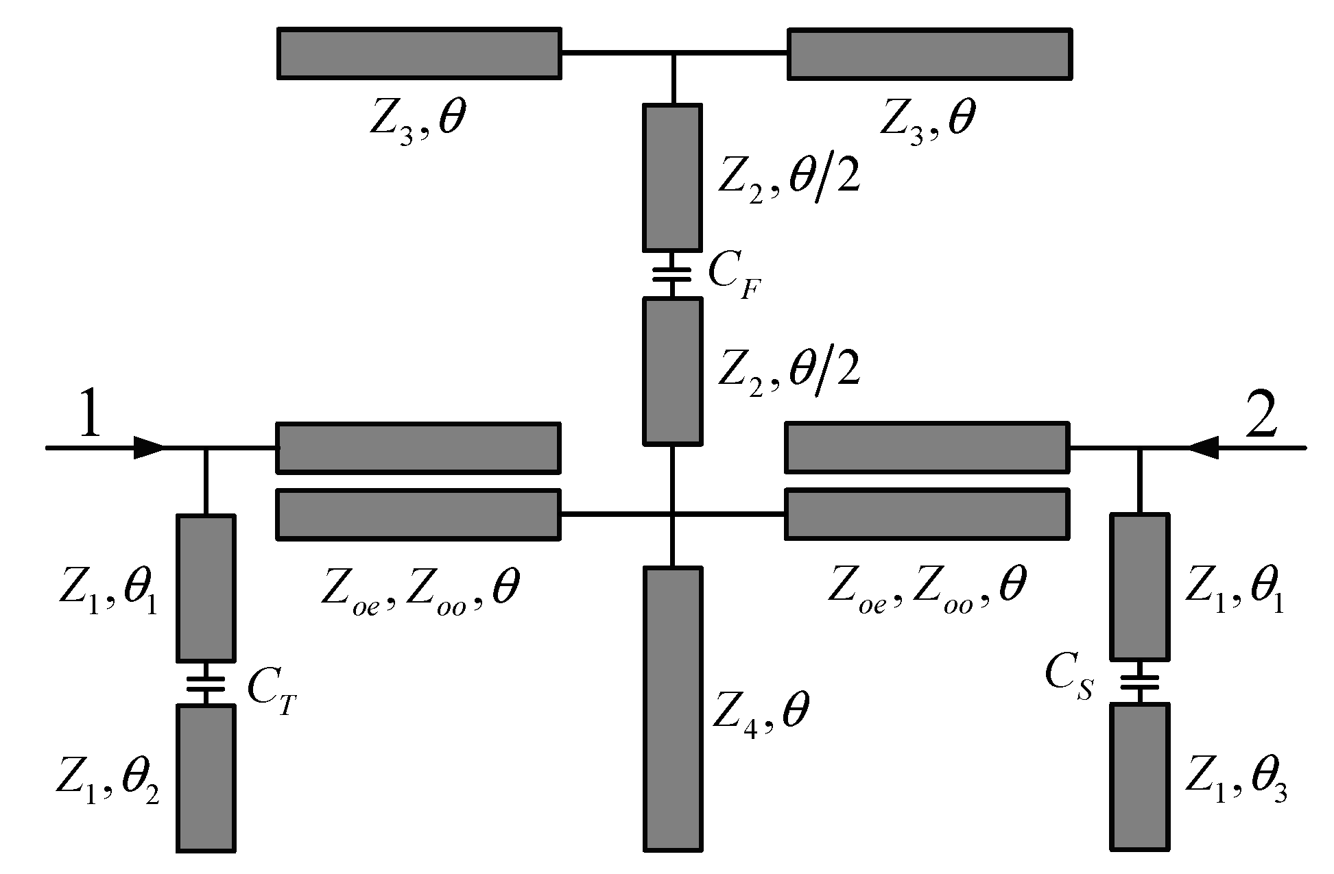
2. Operation Principle and Design

As shown in Figure 1, the novel topology is composed of a passive filtering structure with three capacitors. The passive filtering structure starts from a terminated T-shaped resonator with open terminations, whose characteristic impedances and electrical length are Z3, Z2, Z3, and θ = π/2 at the operating frequency f0, respectively. Thus, its input impedance can be written as
Z i n T = j Z 2 2 Z 2 tan 2 θ Z 3 ( 2 Z 2 + Z 3 ) tan θ
Based on (1), it is apparent that the T-shaped resonator owns a pole f p 1 T and two zeros of f z 1 T , f z 2 T . For arbitrary Z2 and Z3, the relationship of f z 1 T < f p 1 T = f0 < f z 2 T exists. To incorporate it for a dual-band BPF with good filtering responses, extra poles and zeros should be introduced, while the intrinsic pole of f p 1 T must be eliminated. Therefore, a pair of PCLs and three shunt open-ended stubs are added. The parameters of Zoe, Zoo, and θ present the characteristic impedances and electrical length of PCLs, while Z1, Z4, Z1, and θL, θ, θR denote those of the added stubs, where θL = θ1 + θ2, and θR = θ1 + θ3.

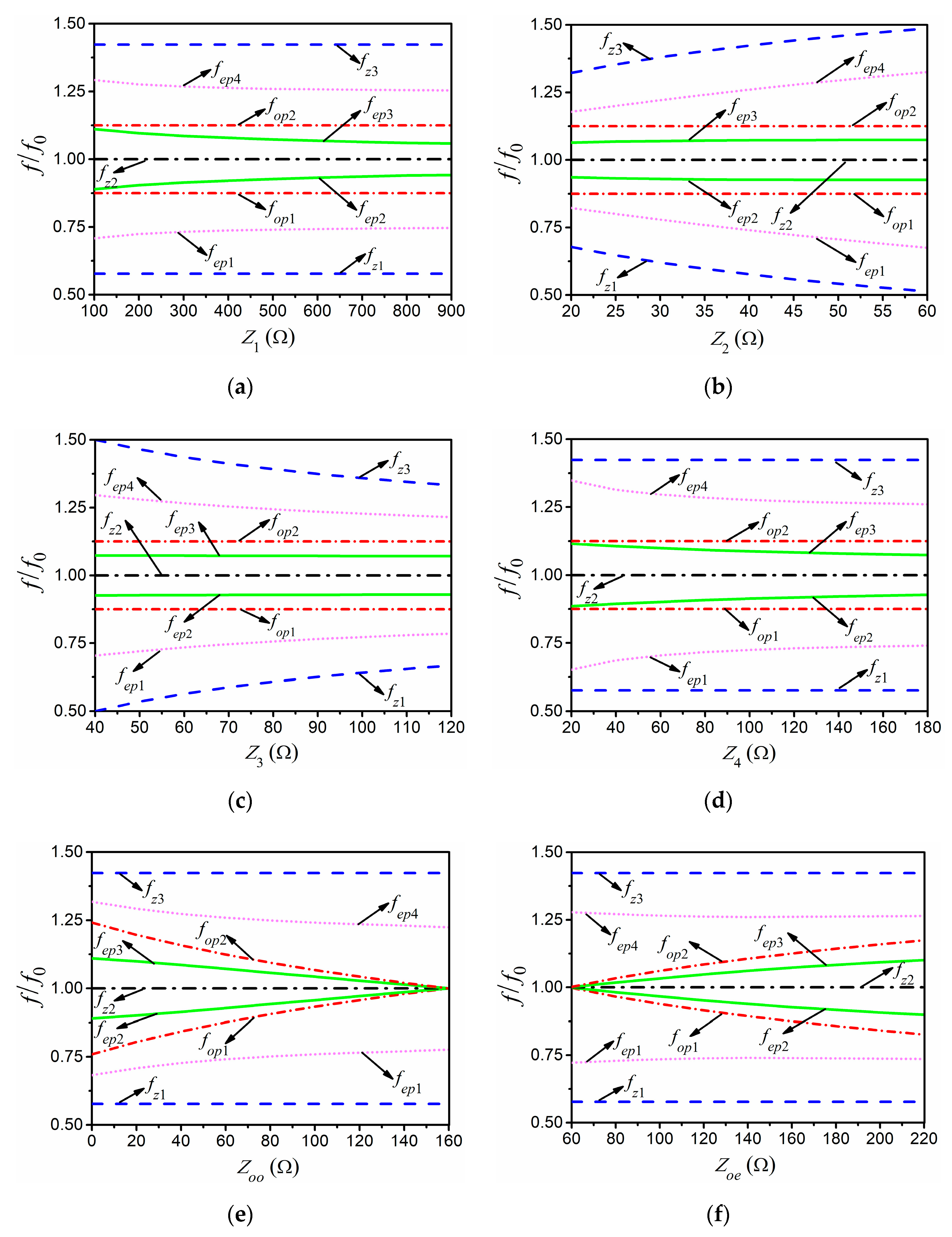
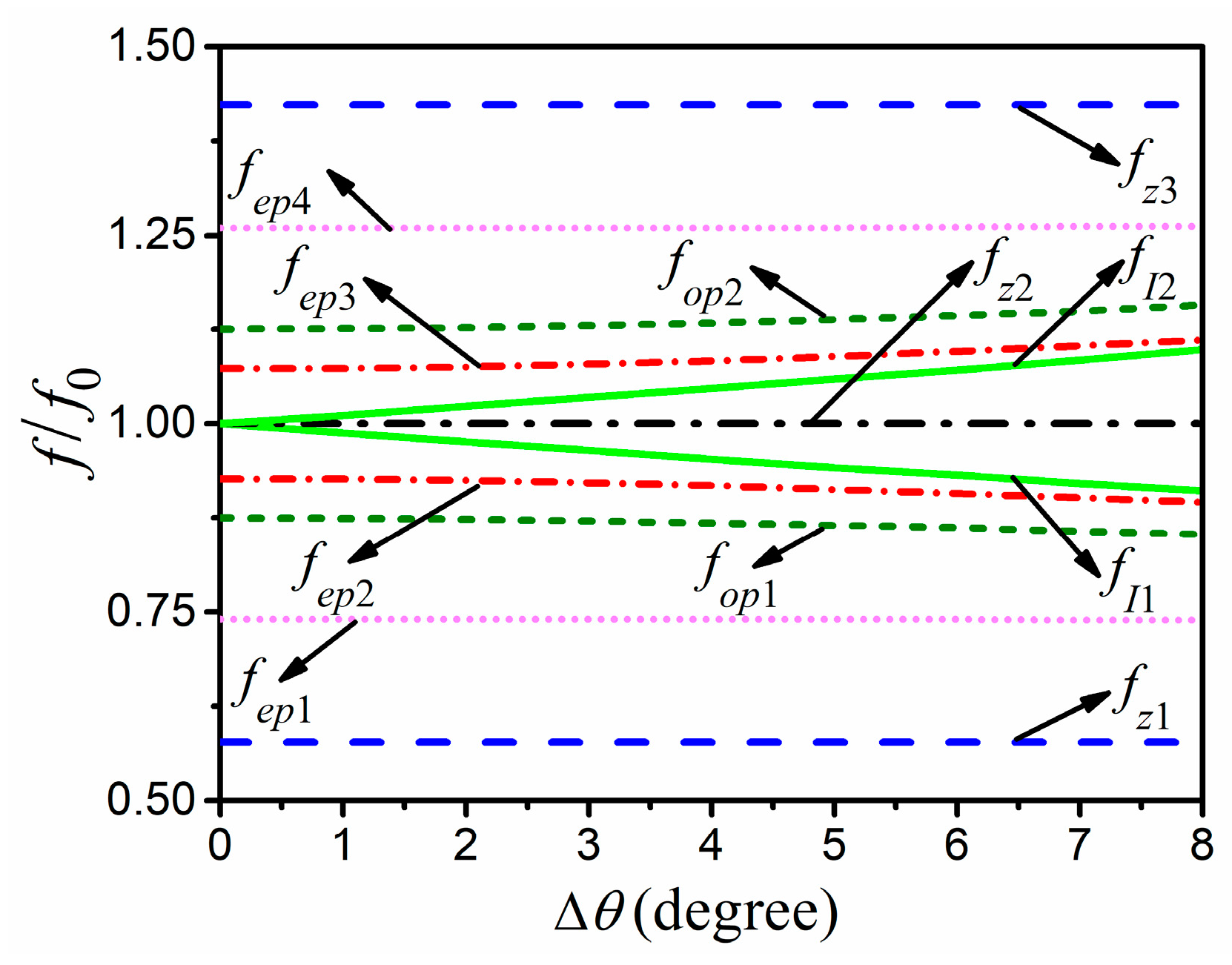
2.1. Transmission Poles and Zeros

To simplify the theoretical analysis, we assume θL = θR = θ at first. Under this condition, the passive filtering structure is symmetrical. Hence, its TPs can be determined by using even–odd-mode analysis method. Figure 2 depicts the odd- and even-mode equivalent circuits. After analyzing the odd-mode equivalent circuit in Figure 2a, its input admittance can be written as
Y i n o = 2 j A tan θ ( A 2 B 2 ) B 2 tan 2 θ + j 1 Z 1 tan θ
where
A = Z o e + Z o o
B = Z o e Z o o
Under the condition that Yino is zero, two odd-mode resonant frequencies can be determined as
f o p 1 = f 0 2 f 0 π arctan ( A 2 B 2 + 2 A Z 1 B 2 )
f o p 2 = f 0 + 2 f 0 π arctan ( A 2 B 2 + 2 A Z 1 B 2 )
For the even-mode equivalent circuit in Figure 2b, its input admittance can be expressed as
Y i n e = j 1 Z 1 tan θ + 2 Y L A tan θ + 4 j tan 2 θ 2 A tan θ + j Y R ( B 2 tan 2 θ + B 2 A 2 )
where
Y R = j 1 2 Z 4 tan θ + 1 2 Z i n T
When Yine is zero, two pairs of even-mode resonant frequencies can be obtained as
f e p 1 = f 0 2 f 0 π arctan Δ 2 + Δ 2 2 4 Δ 1 Δ 3 2 Δ 1
f e p 2 = f 0 2 f 0 π arctan Δ 2 Δ 2 2 4 Δ 1 Δ 3 2 Δ 1
f e p 3 = f 0 + 2 f 0 π arctan Δ 2 Δ 2 2 4 Δ 1 Δ 3 2 Δ 1
f e p 4 = f 0 + 2 f 0 π arctan Δ 2 + Δ 2 2 4 Δ 1 Δ 3 2 Δ 1
where
Δ 1 = Z 2 2 B 2
Δ 2 = 2 Z 2 2 ( 4 A Z 4 + 2 A Z 1 + 8 Z 4 + A 2 B 2 ) + B 2 ( Z 2 Z 3 + Z 3 Z 4 + 4 Z 2 Z 4 )
Δ 3 = ( Z 2 Z 3 + Z 3 Z 4 + 4 Z 2 Z 4 ) ( 2 A Z 1 + A 2 B 2 ) + 4 Z 2 Z 3 Z 4 ( A + 2 Z 1 )
To achieve sharp skirt selectivity and ensure high isolation levels, TZs are essential. For this topo- logy, its TZs can be determined by using even–odd-mode analysis method and S-parameters theory together. The transmission coefficient S21 can be written as
S 21 = Y 0 ( Y i n e Y i n o ) ( Y i n o + Y 0 ) ( Y i n e + Y 0 )
After some algebraic operations, three TZs can be obtained and written as
f z 1 = 2 f 0 π arctan ( Z 3 2 Z 2 )
f z 2 = f 0
f z 3 = 2 f 0 2 f 0 π arctan ( Z 3 2 Z 2 )
It is apparent that the passive filtering structure owns six TPs and three TZs when θL = θR = θ, and all the TPs and TZs are symmetrical to f0. In addition, the relationships of fz1 < fep1 < fop1 < fep2 < fz2 = f0 < fep3 < fop2 < fep4 < fz3 always hold for arbitrary Z1, Zoe, Zoo, Z2, Z3, and Z4. Hence, the proposed topology is suitable to design triple-mode DWB BPFs. Furthermore, the filter bandwidths are mainly controlled by the locations of fep1,2,3,4, while the skirt selectivity near the first and fourth passband edges are mainly determined by those of fz1 and fz2. To better understand this, TPs/TZs with respect to different characteristic impedances of Z1, Z2, Z3, Z4, Zoo, and Zoe, are shown in Figure 3. Obviously, the locations of fep1 and fep4 are sensitive to Z2 and Z3, while the locations of fep2 and fep3 are mainly determined by Zoo and Zoe. Reflected to filter responses, the first and fourth passband edges will move closer to each other as Z2 decreases or Z3 increases, and the second and third ones will move apart as Zoo decreases or Zoe increases. Hence, a filter with a wide bandwidth should own large Z2 and small Z3, while a filter with a large center frequency ratio need choose small Zoo and large Zoe. For the rest of the parameters, they are used to ensure good matching in each passband and sharp skirt near the first and fourth passband edges.
Due to the lack of TZs near the second and third passband edges, the corresponding selectivity is poor under the condition that θL = θR = θ. To deal with this, the electrical length of θL and θR should be studied. To better demonstrate these, a revised topology for the theoretical analysis is shown in Figure 4. First of all, Δθ = 1.11(θθL) = θRθ. When Δθ is zero, there is only one TZ between passbands, as analyzed above. As Δθ increases, another two TZs of fI1 and fI2 are introduced and move apart gradually. Meanwhile, TPs of fep2,3 and fop1,2 move apart slightly. For the rest of the TPs/TZs, they are maintained unaltered, as shown in Figure 5. Hence, the skirt selectivity of the passive filtering structure near the second and third passband edges can be improved by generating TZs of fI1 and fI2 through suitably choosing θL and θR. Furthermore, the relationships among fI1, fI2, θL, and θR can be approximately obtained as
f I 1 π 2 θ R f 0
f I 2 π 2 θ L f 0
One thing should be noted: whatever the electrical lengths of θL and θR are, the relationships of fz1 < fep1 < fop1 < fep2 < fI1 < fz2 = f0 < fI2 < fep3 < fop2 < fep4 < fz3 always exist. Hence, the second and third passband edges can be independently controlled by varying θL and θR, as the ones in [4,23].

2.2. Reconfigurable Properties

To realize the desired reconfigurable properties, some tuning elements should be inserted into the passive filtering structure. At first, a lumped capacitor CF is employed as one of the tuning elements, which is located at the middle of the lower stub of T-shaped resonator with open terminations. Under this condition, the input impedance of T-shaped resonator with capacitor CF can be expressed as
Z i n _ C F T = Z 2 Z i n 1 + j Z 2 tan ( θ / 2 ) Z 2 + j Z i n 1 tan ( θ / 2 )
where
Z i n 1 = j Z 2 Z 3 tan θ + 2 Z 2 tan ( θ / 2 ) 2 Z 2 Z 3 tan ( θ / 2 ) tan θ + 1 j ω C F
If the inserted capacitor CF is large enough, the input impedance of T-shaped resonator with capacitor can be simplified to the one without capacitor. Under this condition, the effect of the inserted capacitor on the filter responses is insignificant. With the decrease in CF, however, the conditions are changed, and the effect of the inserted capacitor CF on fep1 is much larger than the ones on fep2, fep3, fep4. Reflected to the filter responses, the first passband edge can be independently tunable by altering CF, while the other three are fixed, as illustrated in Figure 6a, where the 3-dB passband edges with TZs for sharp selectivity are depicted with respect to different CF.
As mentioned in Part A, the second and third passband edges can be independently controlled by varying θL and θR. Hence, the other two capacitors of CS and CT are then inserted into the open- ended stubs with Z1 for independent tunabilities of these two passband edges. In Figure 6b,c, 3-dB passband edges with TZs for sharp selectivity with respect to different capacitors of CS and CT are depicted. Apparently, these two passbands also can be independently tunable by controlling the capacitors of CS and CT, respectively.
According to the theoretical analysis mentioned above, the first and second passband edges can be independently tunable. Thus, the reconfigurable properties, i.e., independently tunable center frequency of lower passband with fixed absolute bandwidth, and independently tunable bandwidth of lower passband with fixed center frequency, can be directly realized by suitably selecting the capacitors of CF and CS. Furthermore, it is interesting that the lower passband will disappear when CF is small and CS is large enough. Hence, the switchable lower passband also can be achieved. As the third passband edge is independently controlled by the capacitor of CT, a SWB BPF with tunable bandwidth can be designed too. For verification, a prototype with different capacitors is designed and measured, which will be presented in detail in Section 3.

3. Design Examples

Based on the theory in Section 2, a simple and effective design procedure for the desired prototype can be concluded as:
(1)
On the basis of DWB BPF with the widest bandwidth, initially determine the design para-meters of the passive filtering structure, i.e., Z1, Z2, Z3, Z4, Zoo, Zoe, θ1, θ2, and θ3.
(2)
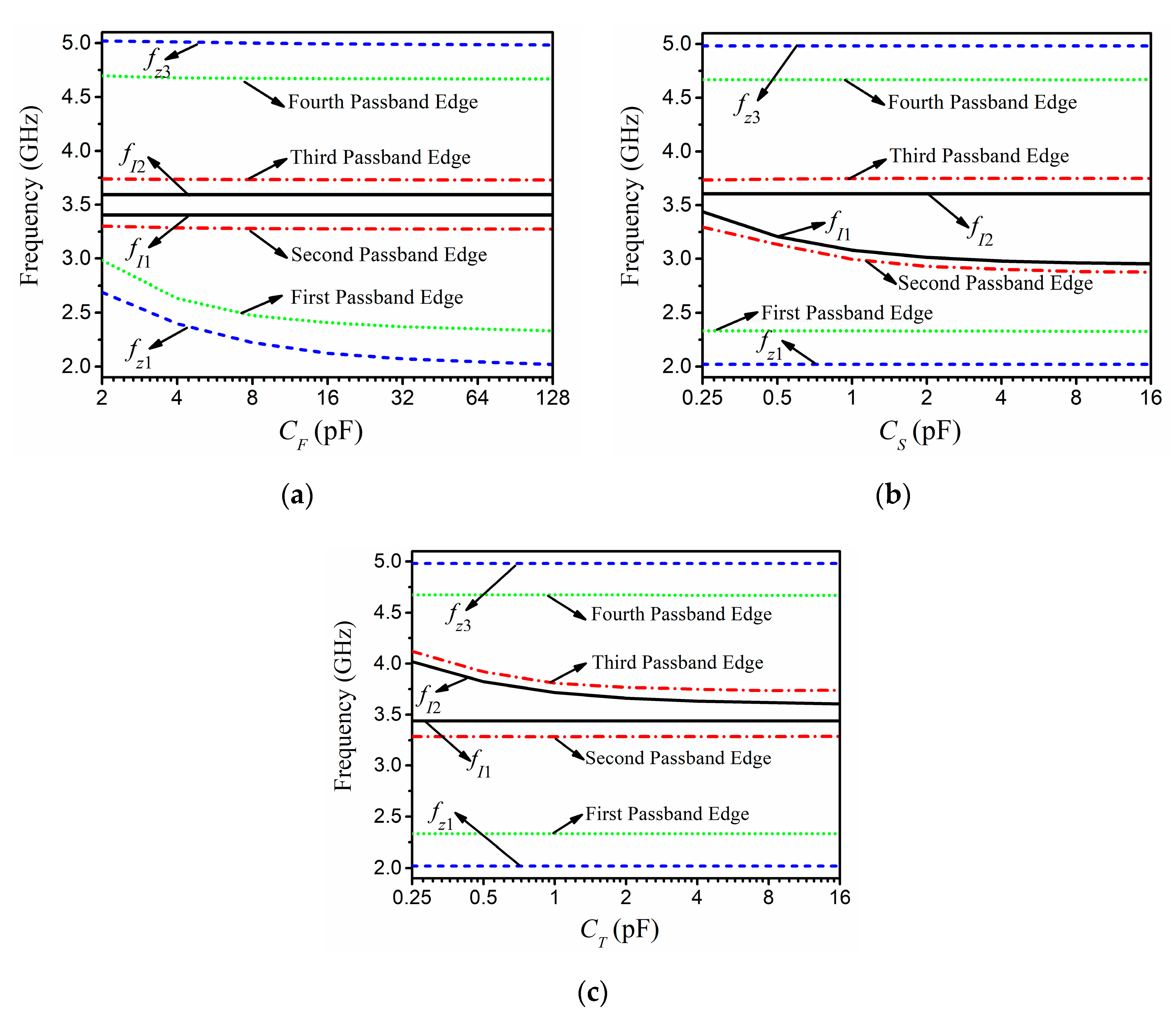
Based on the different locations of first and third passband edges, determine CF and CT.
(3)
Based on the various locations of second passband edge, determine CS and θ3.
(4)
After slightly optimizing, obtain the final parameters.
On the basis of the above procedure, the design parameters of a reconfigurable DWB BPF with widest fractional bandwidths (FBWs) of 25.7%, 17.5%, and center frequencies (CFs) of 2.82 GHz and 4.12 GHz can be concluded as: Z1 = 500 Ω, Z2 = 40 Ω, Z3 = 80 Ω, Z4 = 160 Ω, Zoo = 63 Ω, Zoe = 160 Ω, θ1 = 40°, θ2 = 47.6°, θ3 = 54.2°, CF = CT =100 pF, CS = 2.4 pF, and f0 =3.47 GHz. Then, the reconfigurable properties can be achieved by only changing the inserted capacitors. As the fabricated filter is implemented on Rogers RO4003B with dielectric constant of 3.38 mm and thickness of 0.813 mm, its dimensions and layout can be determined with the aid of commercial software, as shown in Figure 7. In this layout, a design skill is used: to enlarge the equivalent value of Z1 and enhance the coupling strength of PCLs, some parts of the open-ended stubs with Z1 are parallel to PCLs.
The filtering responses under different cases are measured by a Keysight N5224A network analyzer. For Case A with CF = CT = 100 pF, and CS = 2.4 pF, the corresponding measured results are plotted with the simulated ones in Figure 8. Apparently, they agree well with each other, except for some slight discrepancies, which are caused by the fabrication and measured tolerances. Under the condition that the matching is better than 10.0 dB, the measured FBWs are 26.6%, 17.8% with CFs of 2.82 GHz and 4.10 GHz for the first and second passbands, respectively. In addition, over 20-dB insertion loss can be found in the stopband between two passbands from 3.33 GHz to 3.63 GHz, indicating high isolation level. Five TPs for good flatness in the passbands are found at 2.52 GHz, 2.90 GHz, 3.12 GHz, 3.80 GHz, and 4.30 GHz, respectively, while five TZs for sharp skirt and high isolation levels are located at 2.12 GHz, 3.34 GHz, 3.46 GHz, 3.59 GHz, and 4.88 GHz. In addition, the group delay within two passbands is no more than 1.78 ns. The overall size of the fabricated filter is 36.0 × 25.0 mm.

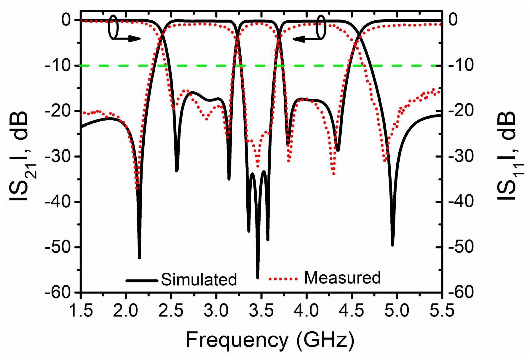
3.1. Three Independently Tunable Passband Edges

The simulated and measured S-parameters of Case B with CF = 4.7 pF, CS = 2.4 pF, and CT = 100 pF are shown in Figure 9a. By comparing Case A and B, it is apparent that the first passband edge with matching better than 10.0 dB can independently move upwards from 2.44 GHz to 2.73 GHz with the decreases of CF from 100 pF to 4.7 pF, while TZ near the first passband edge also moves upwards from 2.12 GHz to 2.42 GHz for sharp skirt. For the other three passband edges and TZs for sharp selectivity, they are unaltered.
Similar to the first passband edge, the second and third ones also can be independently tunable by controlling the capacitors of CS and CT. In Figure 9b,c, the simulated and measured results under Case C (CF = CT = CS = 100 pF) and D (CF = 100 pF, CS = 2.2 pF, and CT = 2.4 pF) are shown, respectively. Compared with Case A and C, it can be obtained that the second passband edge with matching better than 10 dB moves downwards from 3.19 GHz to 2.96 GHz as CT increases from 2.4 pF to 100 pF, while TZ near the second passband moves downwards from 3.34 GHz to 3.26 GHz for sharp skirt. By comparing Case A and D, it is obvious that the third passband edge with matching better than 10.0 dB will move upwards from 3.73 GHz to 3.89 GHz with the decrease in CT from 100 pF to 2.2 pF, while TZs near the third passband are shifted from 3.59 GHz to 3.62 GHz for sharp skirt. For the rest of the passband edges and other TZs, they are unaltered. Hence, the three independently tunable passband edges can be validated.

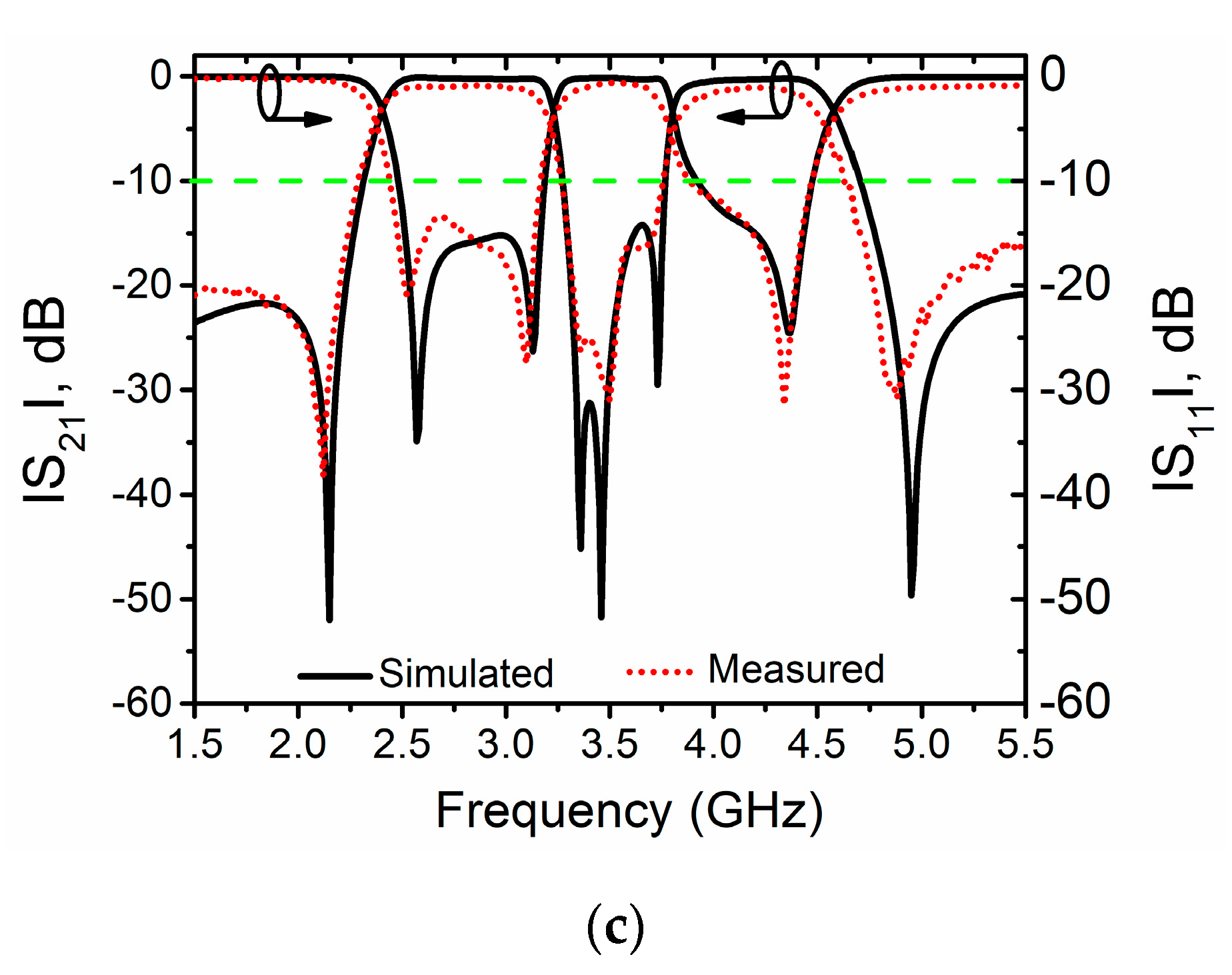
3.2. Independently Tunable Center Frequency of Lower Passband with Fixed Absolute Bandwidth

As the first and second passband edges can be independently tunable by changing the capacitors of CF and CS, respectively, it is apparent that the center frequency of lower passband also can be independently tunable by suitably selecting these two capacitors, while the corresponding absolute bandwidth is fixed. This reconfigurable property is validated by comparing Case B and C. By gradually decreasing CF from 100.0 pF to 2.4 pF and suitably choosing the capacitor of CS, the center frequency of lower passband can be continuously shifted from 2.71 GHz to 2.97 GHz, while the absolute bandwidth with matching better than 10.0 dB is about 0.49 GHz. For the upper passband, it is fixed. Hence, the fractional tuning range of lower passband is 9.6%, and the corresponding constant FBW is 18.1%.
One thing should be noted: only two reported IEEE journal papers concern the tunable center frequencies of dual-band BPFs with constant absolute bandwidths, which are presented in [9] and [17]. Unfortunately, their constant FBWs are narrow and no more than 9.3%. Hence, the proposed design should be beneficial to exploration of other tunable-center-frequency DWB BPFs with constant absolute bandwidths.

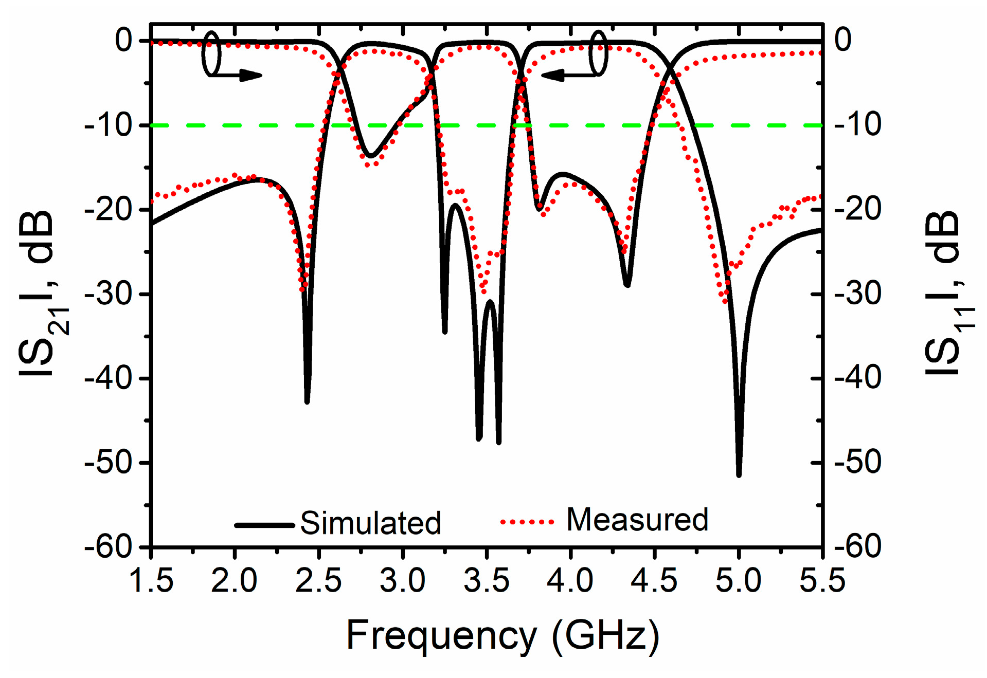
3.3. Independently Tunable Bandwidth of Lower Passband with Fixed Center Frequency

Among the reported tunable DWB BPFs, there is no report of the independently tunable bandwidth of lower passband with constant center frequency, which will restrict the development of telecommunication. In this part, this desired reconfigurable property is implemented.
As the first passband edge will move downwards with the increase in CF, and the second one will move upwards with the decrease in CS, the bandwidth of lower passband can be tunable in continue manners by gradually increasing CF and decreasing CS simultaneously, while the corresponding center frequency and upper passband is unchanged. This reconfigurable property can be validated by comparing Case A and E (CF = 4.8 pF, CS = 6.2 pF, CT = 100 pF), whose simulated and measured results are depicted in Figure 10. By suitably decreasing CF from 100 pF to 4.8 pF and increasing CS from 2.4 pF to 6.2 pF, the FBW of the lower passband is varied from 26.6% to 9.9%, and the corresponding center frequency is about 2.83 GHz. Meanwhile, TZs near the first and second passband edges are shifted from 2.12 GHz and 2.40 GHz to 3.34 GHz and 3.29 GHz, respectively. Furthermore, the upper passband is unaltered. Hence, DWB BPF with independently tunable bandwidth and fixed center frequency of lower passband can be designed.

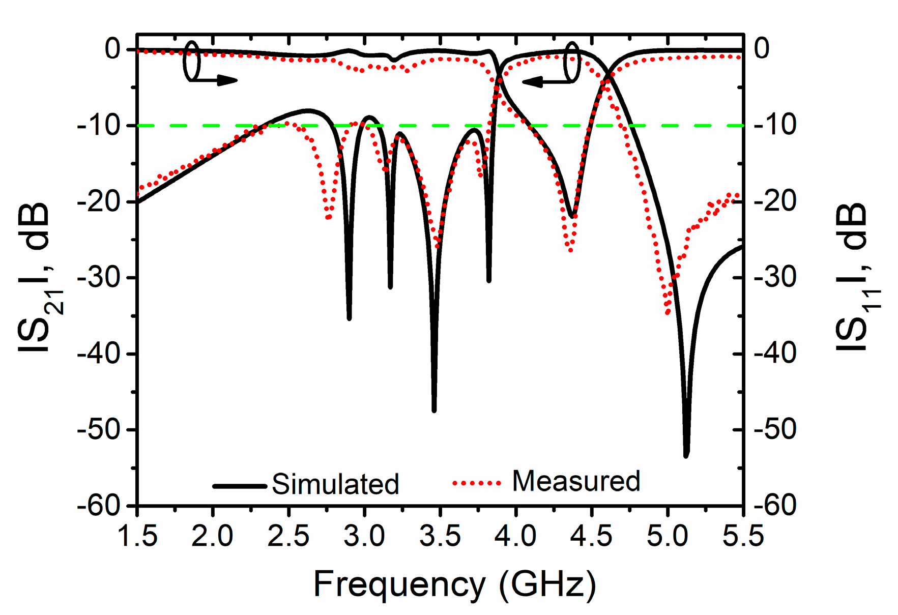
3.4. Independently Switchable Lower Passband

Although the switchable dual-band BPFs have been studied extensively, their corresponding passbands are relatively small, as presented in [15,16,17]. In other words, there is no DWB BPF with independently switchable passbands reported. Therefore, the successful design of DWB BPFs with switchable bandwidth should be beneficial to the modern telecommunication.
As mentioned in Case A with CF = CT = 100 pF, and CS = 2.4 pF, there are two passbands with FBWs of 26.6% and 17.8%. Then, the lower passband will be changed into a stopband under the condition of Case F with CF = 1.5 pF, CS = 100 pF, and CT = 100 pF, while the upper one is almost fixed, as depicted in Figure 11. Thus, the lower passband can be independently switchable.

3.5. Independently Tunable First Passband Edge of SWB BPF

Considering that the lower passband will be changed into a stopband by selecting the suitable capacitors of CF and CS, and the third passband edge can be independently tunable by controlling the capacitor of CT, SWB BPFs with tunable bandwidth can be designed based on this novel topology. This is verified by comparing Case F and G. As shown in Figure 11 and Figure 12, the first passband edge of SWB BPFs is shifted from 3.76 GHz to 4.07 GHz with the decrease in CT from 100 pF to 1.4 pF, while the other one is fixed about 4.50 GHz. In addition, TZ near the first passband edge of SWB BPFs is varied from 3.58 GHz to 3.76 GHz. Thus, a SWB BPF with tunable-bandwidth range of 7.5% can be designed.
In Figure 13, the photograph of the fabricated filter is given. To vividly demonstrate this topology, the simulated and measured results under different cases are listed in Table 1. One thing should be noted—the insertion loss in the passband is no more than 1.4 dB for all the cases, while the group delay is less than 2.35 ns. To demonstrate the advantages of this design, a comparison with some previous works is presented in Table 2. Obviously, the proposed work can not only be used to design SWB BPFs with tunable bandwidth, but also DWB BPFs with tunable center frequency, tunable bandwidth, and switchable passband. Considering the new reconfigurable properties, i.e., tunable bandwidth of lower passband with fixed absolute center frequency, the proposed work can reduce the design complicity and circuit size of multi-functional wireless communication systems effectively and conveniently.

4. Conclusions

In this paper, a novel topology is presented for the design of SWB/DWB BPFs with different reconfigurable properties. This design is based on a dual-wideband passive filtering structure with three TPs in each passband and five TZs in the stopbands, and three capacitors are used as the tuning elements. By controlling the inserted capacitors, it is found that SWB BPFs with tunable bandwidth, and DWB BPFs with tunable center frequency, tunable bandwidths, and switchable passband, can be achieved simultaneously. For verification, a prototype with different capacitors is designed and fabricated. Obviously, the simulated and measured results are in good agreement. Considering that the proposed design owns novel and masses of reconfigurable properties, it is anticipated that this filter can be broadly used in the modern multi-functional telecommunication systems.

Author Contributions

Conceptualization, X.B. and T.Y.; data curation, K.H. and Z.Z.; formal analysis, X.B. and W.H.; funding acquisition, T.Y. and W.H.; investigation, S.G. and Z.Z.; methodology, K.H. and T.Y.; resources, Z.Z. and T.Y.; software, T.Y. and W.H.; supervision, T.Y. and W.H.; validation, S.G. and K.H.; writing—original draft, S.G. and X.B.; writing—review and editing, X.B. All authors have read and agreed to the published version of the manuscript.

Funding

This work is supported in part by the Natural Science Foundation of China under Grant 61801298; the Guangdong Provincial Department of Science and Technology, China, under Project No. 2020B1212030002; the Foundation of Shenzhen under Grants JCYJ20170302142545828 and JCYJ20180305124721920 and No. KQTD 20180412181337494; in part by the National Key Research and Development Program, China, under Subject No.2019YFF0216602; and the Foundation of Shenzhen University under Grants 2016057, 2019119, and 2019120.

Conflicts of Interest

The authors declare no conflict of interest.

References

  1. Hou, Z.Y.; Liu, C.G.; Zhang, B.; Song, R.G.; Wu, Z.P.; Zhang, J.W.; He, D.P. Dual-/Tri-Wideband Bandpass Filter with High Selectivity and Adjustable Passband for 5G Mid-Band Mobile Communications. Electronics 2020, 9, 205. [Google Scholar] [CrossRef] [Green Version]
  2. Yang, L.; Gómez-García, R.; Muñoz-Ferreras, J.-M.; Zhang, R.-Q.; Peroulis, D.; Zhu, L. Multilayered Reflectionless Wideband Bandpass Filters With Shunt/In-Series Resistively Terminated Microstrip Lines. IEEE Trans. Microw. Theory Tech. 2019, 68, 877–893. [Google Scholar] [CrossRef]
  3. Lalbakhsh, A.; Alizadeh, A.M.; Ghaderi, A.; Golestanifar, A.; Mohamadzade, B.; Jamshidi, M.; Mandal, K.; Mohyuddin, W. A Design of a Dual-Band Bandpass Filter Based on Modal Analysis for Modern Communication Systems. Electronics 2020, 9, 1770. [Google Scholar] [CrossRef]
  4. Bi, X.K.; Zhang, X.; Huang, G.; Tao, Y. Compact Microstrip NWB/DWB BPFs With Controllable Isolation Bandwidth for Interference Rejection. IEEE Access 2019, 7, 49169–49176. [Google Scholar] [CrossRef]
  5. Bi, X.K.; Zhang, X.; Wang, S.W.; Yuan, T.; Guo, S.H. Design of Equal-Ripple Dual-Wideband Bandpass Filter With Minimum Design Parameters Based on Cross-Shaped Resonator. IEEE Trans. Circuits Syst. II Express Briefs 2020, 67, 1780–1784. [Google Scholar] [CrossRef]
  6. Mostrah, A.E.; Muller, A.; Favennec, J.-F.; Potelon, B.; Manchec, A.; Ruis, E.; Quendo, C.; Clavet, Y.; Doukhan, F.; Le Nezet, J. An RF-MEMS-Based Digitally Tunable SIW Filter in X-Band for Communication Satellite Application. Appl. Sci. 2019, 9, 1838. [Google Scholar] [CrossRef] [Green Version]
  7. Ohira, M.; Hashimoto, S.M.; Ma, Z.-W.; Wang, X.L. Coupling-Matrix-Based Systematic Design of Single-DC-Bias-Controlled Microstrip Higher Order Tunable Bandpass Filters With Constant Absolute Bandwidth and Transmission Zeros. IEEE Trans. Microw. Theory Tech. 2018, 67, 118–128. [Google Scholar] [CrossRef]
  8. Lu, D.; Yu, M.; Barker, N.S.; Li, Z.-Y.; Li, W.; Tang, X.-H. Advanced Synthesis of Wide-Tuning-Range Frequency-Adaptive Bandpass Filter With Constant Absolute Bandwidth. IEEE Trans. Microw. Theory Tech. 2019, 67, 4362–4375. [Google Scholar] [CrossRef]
  9. Khani, S.; Mousavi, S.M.H.; Danaie, M.; Rezaei, P. Tunable compact microstrip dual-band bandpass filter with tapered resonators. Microw. Opt. Technol. Lett. 2018, 60, 1256–1261. [Google Scholar] [CrossRef]
  10. Xu, J.; Wu, W.; Wei, G. Novel Dual-Band Bandpass Filter and Reconfigurable Filters Using Lumped-Element Dual-Resonance Resonators. IEEE Trans. Microw. Theory Tech. 2016, 64, 1496–1507. [Google Scholar] [CrossRef]
  11. Bi, X.-K.; Cheng, T.; Cheong, P.; Ho, S.-K.; Tam, K.-W. Wideband bandpass filters with reconfigurable bandwidth and fixed notch bands based on terminated cross-shaped resonator. IET Microw. Antennas Propag. 2019, 13, 796–803. [Google Scholar] [CrossRef]
  12. Zhang, B.; Li, S.-S.; Huang, J.-M. High performance tunable bandpass filter with separately reconfigurable passband edges. Microw. Opt. Technol. Lett. 2015, 57, 1111–1113. [Google Scholar] [CrossRef]
  13. Wang, X.M.; Bi, X.-K.; Guo, S.H.; He, J.; Li, C.L.; Liu, J.J.; Hu, G.Q.; Ma, G.J.; Xu, Z.-T. Synthesis Design of Equal-Ripple and Quasi-Elliptic Wideband BPFs with Independently Reconfigurable Lower Passband Edge. IEEE Access 2020, 8, 76856–76866. [Google Scholar] [CrossRef]
  14. Bi, X.K.; Zhang, X.; Wang, S.W.; Guo, S.H.; Yuan, T. Synthesis Design of Chebyshev Wideband Band-Pass Filters With Independently Reconfigurable Lower Passband Edge. IEEE Trans. Circuits Syst. II Express Briefs 2020, 67, 2948–2952. [Google Scholar] [CrossRef]
  15. Chuang, M.-L.; Wu, M.-T. Switchable Dual-Band Filter with Common Quarter-Wavelength Resonators. IEEE Trans. Circuits Syst. II Express Briefs 2015, 62, 347–351. [Google Scholar] [CrossRef]
  16. Lee, V.; Lee, S.; Sis, S.A.; Mortazawi, A. Intrinsically Switchable Frequency Reconfigurable Barium Strontium Titanate Resonators and Filters. IEEE Trans. Microw. Theory Tech. 2017, 65, 3221–3229. [Google Scholar] [CrossRef]
  17. Lu, D.; Tang, X.H.; Barker, N.S.; Feng, Y.K. Single-Band and Switchable Dual-/Single-Band Tunable BPFs With Predefined Tuning Range, Bandwidth, and Selectivity. IEEE Trans. Microw. Theory Tech. 2017, 66, 1215–1227. [Google Scholar] [CrossRef]
  18. Chaudhary, G.; Jeong, Y.; Lim, J. Dual-Band Bandpass Filter with Independently Tunable Center Frequency and Bandwidths. IEEE Trans. Microw. Theory Tech. 2012, 61, 107–116. [Google Scholar] [CrossRef]
  19. Wu, Y.; Nan, L.; Jiao, L.; Wang, W.; Liu, Y. Dual-band coupled-line bandpass filter with independently tunable bandwidths. China Commun. 2016, 13, 60–64. [Google Scholar] [CrossRef]
  20. Kumar, N.; Singh, Y.K. RF-MEMS-Based Bandpass-to-Bandstop Switchable Single- and Dual-Band Filters with Variable FBW and Reconfigurable Selectivity. IEEE Trans. Microw. Theory Tech. 2017, 65, 3824–3837. [Google Scholar] [CrossRef]
  21. Bi, X.-K.; Cheng, T.; Cheong, P.; Ho, S.-K.; Tam, K.-W. Design of Dual-Band Bandpass Filters with Fixed and Reconfigurable Bandwidths Based on Terminated Cross-Shaped Resonator. IEEE Trans. Circuits Syst. II Express Briefs 2018, 66, 317–321. [Google Scholar] [CrossRef]
  22. Simpson, D.J.; Gómez-García, R.; Psychogiou, D. Single-/Multi-Band Bandpass Filters and Duplexers with Fully Reconfigurable Transfer-Function Characteristics. IEEE Trans. Microw. Theory Tech. 2019, 67, 1854–1869. [Google Scholar] [CrossRef]
  23. Bi, X.K.; Zhang, X.; Wang, S.W.; Guo, S.H.; Yuan, T. Reconfigurable-Bandwidth DWB BPF with Fixed Operation Frequency and Controllable Stopband. IEEE Trans. Circuits Syst. II Express Briefs 2020. to be published. [Google Scholar] [CrossRef]
Figure 1. The novel topology for the proposed filters (θL = θ1 + θ2, θR = θ1 + θ3).
Electronics 09 02149 g001
Figure 2. (a) Odd- and (b) even-mode equivalent circuits (θL = θR = θ).
Electronics 09 02149 g002
Figure 3. Transmission poles/ transmission zeros (TPs/TZs) with respect to varied characteristic impedances of (a) Z1; (b) Z2; (c) Z3; (d) Z4; (e) Zoo; (f) Zoe (The reference parameters are: Z1 = 500 Ω, Z2 = 40 Ω, Z3 = 80 Ω, Z4 = 160 Ω, Zoo = 63 Ω, Zoe = 160 Ω).
Electronics 09 02149 g003
Figure 4. The revised topology for theoretical analysis (θL = θ1 + θ2, θR = θ1 + θ3).
Electronics 09 02149 g004
Figure 5. TPs and TZs with respect to different Δθ.
Electronics 09 02149 g005
Figure 6. 3-dB passband edges with TZs for sharp skirt with respect to different (a) CF; (b) CS; (c) CT.
Electronics 09 02149 g006
Figure 7. Layout of the fabricated filter (l1 = 12.2 mm, l1_L = 2.05 mm, l1_R = 4.35 mm, w1 = 0.3 mm, s1 = 0.5 mm, lF = 13.6 mm, wF = 0.3 mm, sF = 0.1 mm, l2 = 13.75 mm, w2 = 2.4 mm, l3 = 13.4 mm, w3 = 0.1 mm, l4_V = 3.6 mm, l4_H = 10.8 mm, w4 = 0.1 mm).
Electronics 09 02149 g007
Figure 8. Filter responses of Case A (CF = 100 pF, CS = 2.4 pF, CT = 100 pF).
Electronics 09 02149 g008
Figure 9. Filter responses with respect to (a) Case B: CF = 4.7 pF, CS = 2.4 pF, CT = 100 pF; (b) Case C: CF = 100 pF, CS = 100 pF, CT = 100 pF; (c) Case D: CF = 100 pF, CS = 2.4 pF, CT = 2.2 pF.
Electronics 09 02149 g009aElectronics 09 02149 g009b
Figure 10. Filter responses of Case E (CF = 4.8 pF, CS = 6.2 pF, CT = 100 pF).
Electronics 09 02149 g010
Figure 11. Filter responses of Case F (CF = 1.5 pF, CS = 100 pF, CT = 100 pF).
Electronics 09 02149 g011
Figure 12. Filter responses of Case G (CF = 1.5 pF, CS = 100 pF, CT = 1.4 pF).
Electronics 09 02149 g012
Figure 13. The photograph of the fabricated filter.
Electronics 09 02149 g013
Table 1. Simulated and measured results under different cases.
Lower PassbandUpper Passband Lower PassbandUpper Passband
First 1Second 2Third 3Fourth 4First 1Second 2Third 3Fourth 4
Case ASimulated2.48 GHz3.20 GHz3.74 GHz4.48 GHzCase ESimulated2.73 GHz2.96 GHz3.75 GHz4.48 GHz
Measured2.44 GHz3.19 GHz3.73 GHz4.46 GHzMeasured2.70 GHz2.98 GHz3.74 GHz4.48 GHz
Case BSimulated2.75 GHz3.21 GHz3.74 GHz4.48 GHzCase FSimulatedN/AN/A3.78 GHz4.49 GHz
Measured2.73 GHz3.21 GHz3.75 GHz4.49 GHzMeasuredN/AN/A3.76 GHz4.51 GHz
Case CSimulated2.48 GHz2.93 GHz3.75 GHz4.47 GHzCase GSimulatedN/AN/A4.09 GHz4.49 GHz
Measured2.47 GHz2.96 GHz3.72 GHz4.48 GHzMeasuredN/AN/A4.07 GHz4.49 GHz
Case DSimulated2.48 GHz3.19 GHz3.92 GHz4.48 GHz
Measured2.44 GHz3.17 GHz3.89 GHz4.47 GHz
First 1: First passband edge with matching better than 10.0 dB; Second 2: Second passband edge with matching better than 10.0 dB; Third 3: Third passband edge with matching better than 10.0 dB; Fourth 4: Fourth passband edge with matching better than 10.0 dB.
Table 2. Comparison with previous works.
SWB BPFsDWB BPFs SWB BPFsDWB BPFs
TBW 1TCF 2TBW 1SPB 3TBW 1TCF 2TBW 1SPB 3
[9]NoYesNoNoFilter B in [17]NoYesNoYes
[10]NoYesNoNoFilter B in [20]NoNoYesNo
[12]YesNoNoNoFilter B in [22]NoYesYesNo
[13]YesNoNoNoThis workYesYesYesYes
[16]NoNoNoYes
TBW 1: tunable bandwidth; TCF 2: tunable center frequency; SPB 3: switchable passband.
Publisher’s Note: MDPI stays neutral with regard to jurisdictional claims in published maps and institutional affiliations.

