Article

Assessment of Structural Performance and Integrity for Vibration-based Energy Harvester in Frequency Domain

1
CV Innovation Growth Center, Jeonbuk Institute of Automotive Convergence Technology, Gunsan 54158, Korea
2
Department of Mechanical Engineering, Kunsan National University, Gunsan 54150, Korea
*
Author to whom correspondence should be addressed.
Electronics 2020, 9(2), 357; https://doi.org/10.3390/electronics9020357
Submission received: 20 January 2020 / Revised: 5 February 2020 / Accepted: 17 February 2020 / Published: 20 February 2020
(This article belongs to the Special Issue Energy Harvesting and Storage Applications)

Abstract

:
A vibration-based energy harvester (VEH) utilizes vibrations originated from various structures and specifically maximizes the displacement of its moving parts, using the resonance between the frequency of external vibration loads from the structure and the natural frequency of VEH to improve power production efficiency. This study presents the procedure to evaluate the structural performance and structural integrity of VEH utilized in a railway vehicle under frequency domain. First of all, a structural performance test was performed to identify the natural frequency and assess the structural response in frequency domain. Then, the static structural analysis was carried out using FE analysis to investigate the failure critical locations (FCLs) and effect of resonance. Finally, we conducted a frequency response analysis to identify the structural response and investigate the structural integrity in frequency domain. Based on these results, the authors assessed the structural performance and integrity of VEHs in two versions.

1. Introduction

Recently, structural defects or environmental factors have often led to the collapse or breakdown of structures [1,2,3]. Accordingly, the focus on the reliability or integrity of structures is drastically increasing, and relevant techniques are being developed. A typical example is a system for real-time monitoring for structural integrity. This technique is used to inspect abnormalities in the components or structures using sensors and measuring instruments, thereby predicting the damage caused by defects [4]. However, it is time-consuming and costly to wire sensors and equipment, and it is difficult to identify the damage inflicted to components installed in places such as railway vehicles and wind-power conversion systems, which are difficult to access [5]. A monitoring system using wireless sensors is being currently developed to solve this problem, but the limited battery life causes some issues in replacement and maintenance [6]. Hence, a technology is required that can supply power consistently to a wireless sensor system.
The energy harvesting system [7] is used to convert and subsequently store the energy from sunlight, vibration, heat, and wind power as electrical energy. Among them, the vibration-based energy harvester (VEH) [8], which can be applied to various applications and extract energy from vibrations, has been recognized as an area of intensive research. VEH utilizes vibrations originated from several structures or components, and particularly maximizes the power output based on the resonance between the excitation frequency of the external load, which comes from structures, and the natural frequency of VEH, thereby improving the efficiency of power production [9].
In comparison to typical structures that are designed to avoid resonance, VEH is subjected to high level accelerations and loads due to the foregoing resonance; hence, the VEH is very likely to be structurally damaged. Thus, in the case of the VEH, a stricter and more elaborate research into structural performance and integrity are essential.
Among the studies addressing the performance evaluation of VEH, Xu et al. [10], Youn et al. [11], and Uzun et al. [12] evaluated the power performance of a cantilever-type VEH using a piezoelectric element for its electric power. Patel et al. [13] and Chen et al. [14] examined the power variation in the VEH based on the direction of installation. These studies have extensively investigated the power performance of the VEH; however, there is little study dealing with the structural performance and relevant procedure.
To obtain basic data for developing a procedure for evaluating the structural performance of the VEH, we surveyed the existing studies on the structural performance evaluation procedure of traditional structures, which are designed to avoid resonance. We identified that most studies employed experimental or analytical methods [15,16,17]. For example, Zambrano et al. [15] conducted a structural analysis of the axes of a bridge crane by applying chemical and structural properties and other measurements, such as hardness, to evaluate the structural integrity performance. Zhao et al. [16] carried out a structural analysis identifying the easily damaged points of the rear suspension of a torsion beam and obtained the stress. Ozsoy et al. [17] performed a vibration test and analysis for the components of a helicopter and proposed a method of evaluating the structural performance. These studies reported adequate results for the structural performance evaluation of traditional structures; however, they have not considered the resonance between the excitation and the structures. Kang et al. [18] studied experimentally the structural performance of the vibration-based energy harvester; they only, however, introduced the experimental results for structural performance for VEHs, and did not discuss the structural integrity and relevant assessment methodology. Accordingly, the methods employed in these studies are hardly applicable to evaluate the structural integrity of the VEH, which utilizes the resonance.
In this study, we developed a procedure to assess the structural performance and integrity of the VEH. Firstly, static performance tests were performed using the incremental sinusoidal sweep test at the predefined range of frequency and vibration level. Next, we carried out a static structural analysis to identify the natural frequency and failure critical locations (FCL). We then conducted frequency response analysis to identify the stress at the FCL along with the frequency. Using these results, the authors studied the structural performance and integrity of VEHs in two versions considering the resonance between external force and natural frequency.

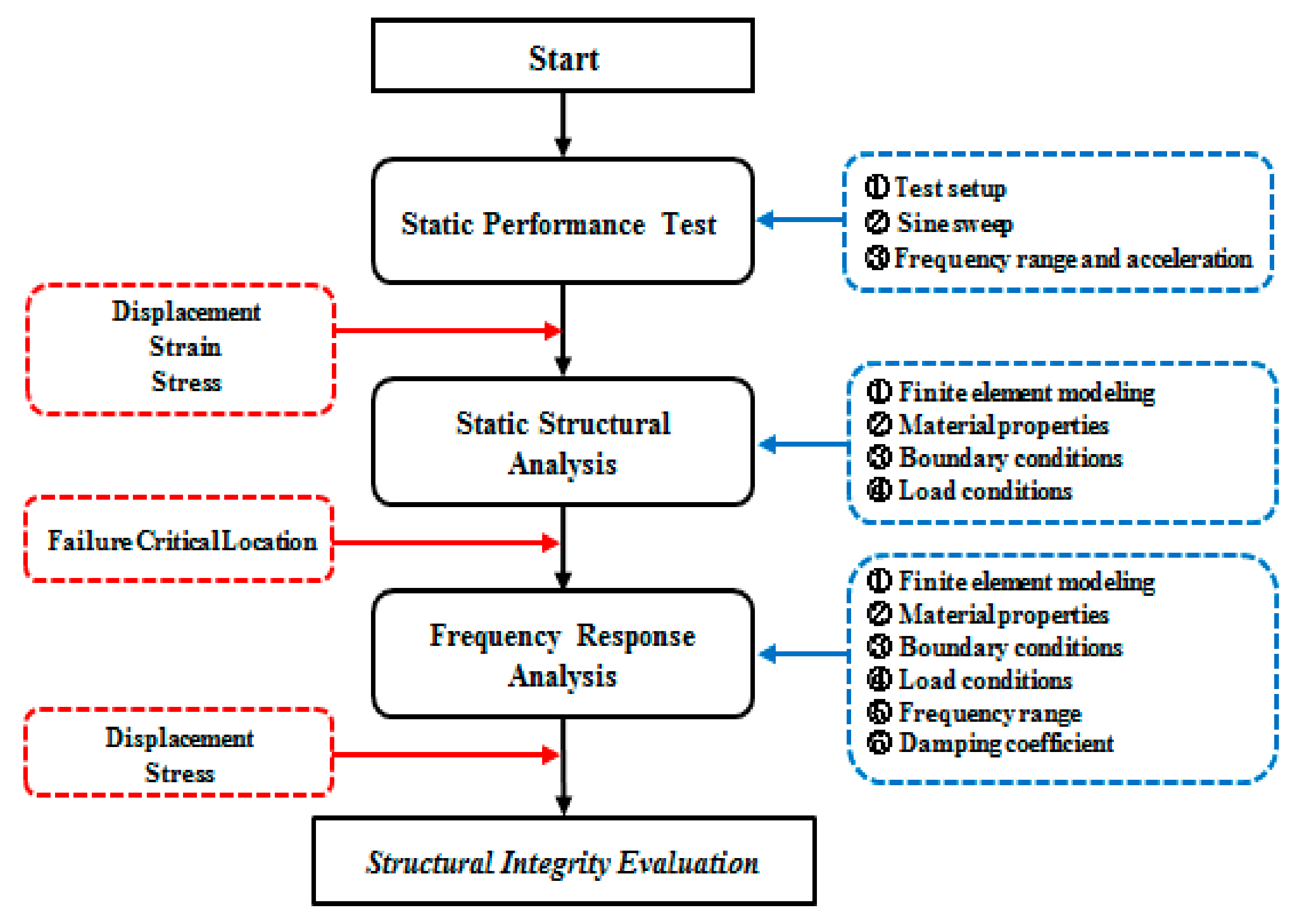
2. Development of Structural Performance Evaluation Procedure

We developed the procedure to assess the structural performance and integrity of VEH, as described in Figure 1. The detailed process is as follows.
(1)
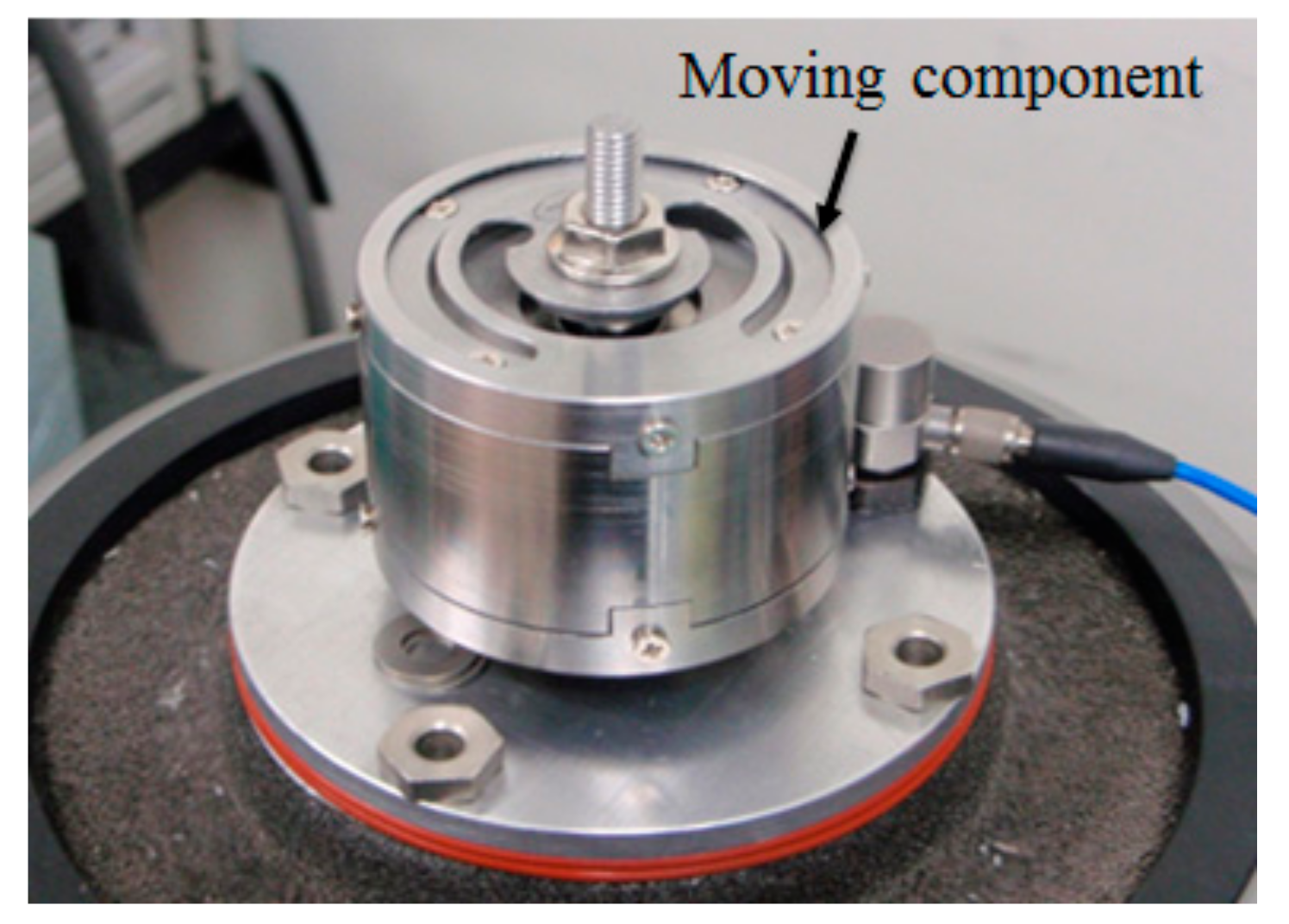
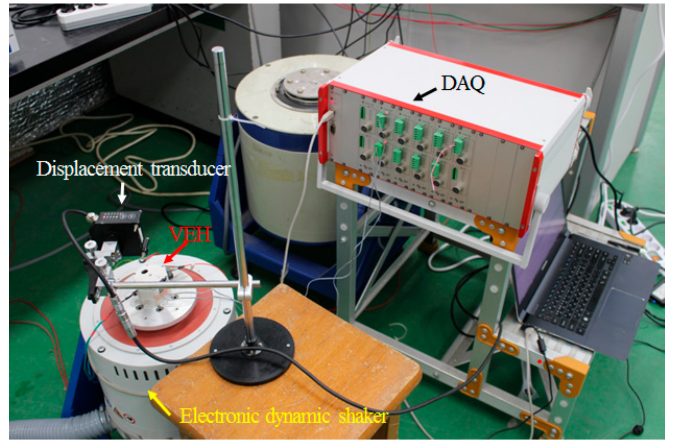
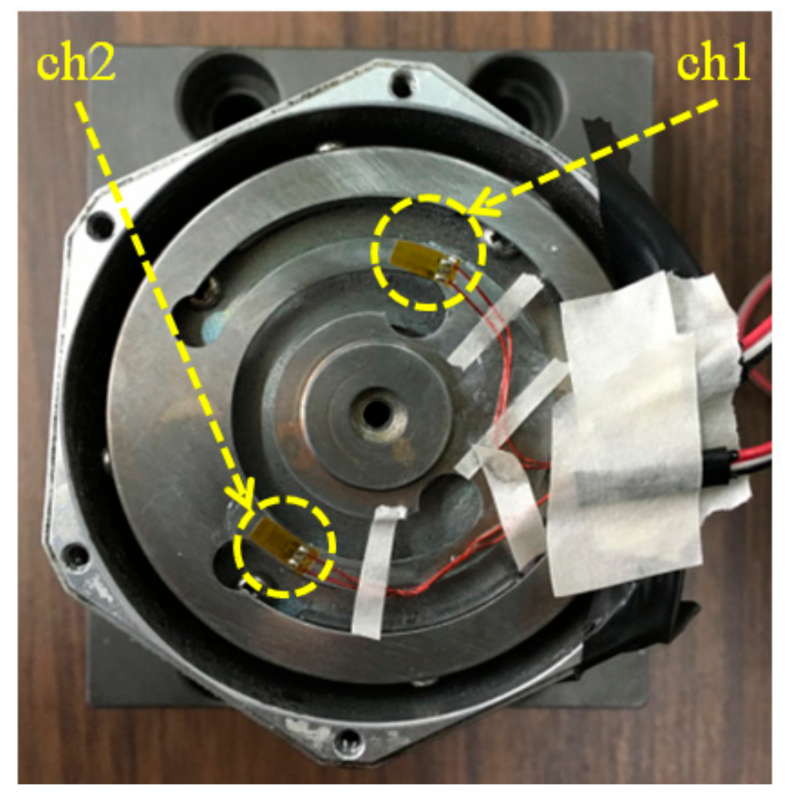
A static performance test: this is the incremental sinusoidal sweep test at the predefined frequency range and acceleration level, which depend on the characteristics of the VEH; here, they were set to the current natural frequency ± 5 Hz and acceleration in the range of 0.5–3 g, respectively. A laser displacement sensor was used to measure the displacement of the LEA’s spring-shaped moving component, and strain gauges were attached to the FCL to measure the strain using the data acquisition unit.
(2)
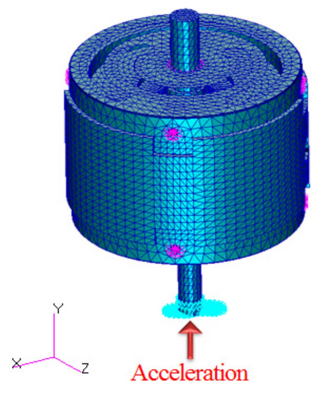
A static structural analysis: a FE analysis was conducted to identify the eigenvalue and structural behavior of the VEH under the same load and boundary conditions as those in the static performance test. The authors could identify the natural frequency and the maximum stress location (failure critical location, FCL) of the VEH.
(3)
A frequency response analysis: to obtain the structural response of the VEH in frequency domain, the frequency response analysis was carried out using the FE software. Here, the identical load and boundary conditions as those of the above steps were applied. The damping coefficient was set in accordance with the displacement measured at the static performance test. Based-on this analysis result, we could get the displacement and stress against the frequency at the FCLs.
(4)
Based on the static performance test, the structural performance and integrity of the VEH were evaluated.

2.1. Static Performance Test

The VEH in this study (Figure 2) was designed to be fixed to a vibration-generating structure through a main shaft; the vibration is carried to the main body via a leaf-spring-shaped moving component, which joins the main shaft and the main body. To identify the performance of this VEH, the natural frequency and displacement of the moving component were obtained from the static performance test, i.e., the incremental sinusoidal sweep test under the predefined frequency range and acceleration level. As shown in Figure 3, the test was conducted by installing a VEH and a laser displacement sensor on an electro-magnetic vibration shaker. In addition, strain gauges were attached at the failure critical location for stress, as shown in Figure 4. The frequency range was the natural frequency (fn) ± 5 Hz with increments of 0.5 and 1 Hz for VEH in two versions, respectively, and the acceleration levels were set to 0.5, 1, 2, and 3 g for all the VEHs.
A data recorder (National Instruments) was employed to measure the acceleration level of the VEH and displacement of the moving component during the static performance test. The analog signals measured by the DAQ were converted into a digital signal at a sampling rate of 1 kHz.

2.2. Static Structural Analysis

Because the VEH generates electric power by maximizing displacement through resonance, the natural frequency of the VEH should be identified firstly. Hence, we performed a modal analysis and a static analysis by using the MSC Patran/Nastran [19]. As the boundary conditions of the modal analysis, the six degrees of freedom were fixed on the lower part of the main shaft. A static analysis was also conducted to identify the failure critical locations of the VEH and the corresponding stresses under static loads. The boundary conditions of the analysis were the same as those of the performance test. An inertial load of 1 g was then applied as the load condition.

2.3. Frequency Response Analysis

The frequency response analysis was carried out to obtain the structural response of the VEH against the frequency of excitation in frequency domain. All directions except the Y-axis, which is the load direction of the bottom part of the main shaft, were fixed. Accelerations of 0.5, 1, 2, and 3g were applied to the bottom part of the shaft. The frequency range was set to the natural frequency ±40 Hz with an increment of 0.2 Hz. In addition, the damping coefficient was set in accordance with the displacement measured in the performance test.

3. Results and Discussion

We analyzed the structural response and performance of VEHs in two versions (Ver. I and Ver. II). The VEH (Figure 2) studied comprises housing, a shaft carrying external load, a main body with a coil case, a neodymium magnet, and a leaf-spring-shaped moving component [18]. In Ver. I VEH, the material of the spring was STS 410, which is martensitic stainless steel, and its thickness was 0.65 mm. This Ver. I VEH was designed to have a natural frequency of fn,1 51 Hz with a 4 mm displacement limit. The Ver. II VEH has a rubber stopper that can restrict the displacement of 2 mm at both ends. The material of the spring was SKD61, which is high strength tool steel. Its thickness and natural frequency were 0.7 mm and fn,2 46 Hz, respectively.

3.1. Results of the Static Performance Test

The performance of the VEH was evaluated through the incremental sinusoidal sweep tests, whose frequency ranges are natural frequencies ±5 Hz with 1 Hz increment and 0.5 Hz increment for Ver. I and II VEHs, respectively. Accelerations of 0.5 g, 1 g, 2 g and 3 g were applied to both VEHs.
Figure 5 exhibits the maximum displacement at almost the outmost rim of the moving component measured using the laser sensor against the frequency of external loads. In Figure 5a for Ver. I VEH with a displacement limit of 4mm, the result indicates that the maximum displacement occurs at the natural frequency, and displacement reduces as the external frequency moves away from the natural frequency. The maximum displacement at the nominal acceleration of 2 g did, however, not differ significantly from the results at nominal acceleration of 1 g. It could be inferred that this came from the fact that the maximum allowable displacement of the moving component in Ver. I VEH is 4 mm. However, in Figure 5b for Ver. II VEH with a displacement limit of 2 mm, the displacement behavior is quite different from the results of Ver. I VEH; in the case of the acceleration level of 0.5 g, its behavior is a little similar to that of Ver. I. However, when the acceleration was 1 g or higher, the maximum displacements are almost constant regardless of excitation frequency. These are attributed to the fact that the displacement limit of Ver. II is just 2 mm.
To investigate the structural integrity of the moving component in Ver. II VEH, we examined the strain and stress response of the moving component against the excitation frequency, as shown in Figure 6. Figure 6a reveals the measurements of the strain almost at the rim of the moving component with the excitation frequency. As shown in Figure 6a, when the acceleration is 0.5 g, the strain increases approaching the natural frequency; but, at about 1 Hz away from the natural frequency, the strain reaches a plateau. This behavior is due to the displacement limit of 2mm in Ver. II VEH. This becomes more apparent with increase in acceleration level; at 2 g, the strains are almost constant with a little gradient. These behaviors of the saturation also appear in the stress response against the excitation frequency due to the displacement limit of Ver. II VEH in Figure 6b. In addition, the stress is restricted to about 230 MPa, evenly in the case of 2 g. This demonstrates that the displacement limit for a leaf-spring shaped moving component is quite useful to the structural integrity of VEH.

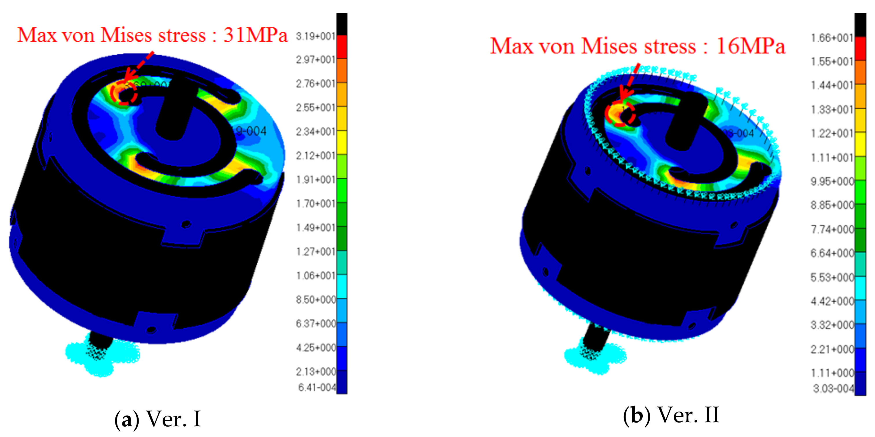
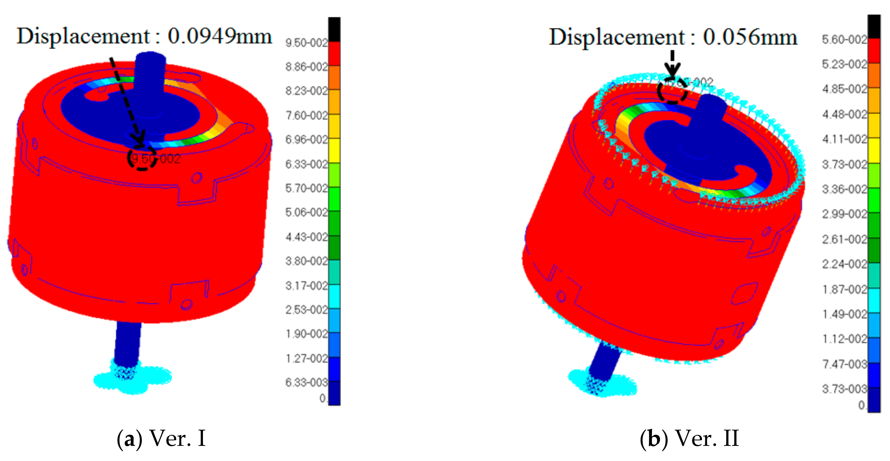
3.2. Results of the Static Analysis

Identifying the natural frequency and FCLs of each VEH, we performed static analysis using the FE model in Figure 7. The FE model was made by using solid (CTETRA) and shell (CTRIA3) elements, with elements of 49,064 and nodes of 14,507. MPC (multi-point constraints) were employed between the solid and shell elements to avoid mismatching the hinge connections in degree of freedom. Table 1 summarizes the material properties of VEHs.
Firstly, the modal analysis was conducted to identify the natural frequency of VEHs, which is the most important factor for both the performance and structural integrity of VEHs. Table 2 shows the relative error of modal analysis with the experimental results for both VEHs. The analysis results well describe the experimental results for both the VEHs.
To identify the FCLs, which mean the most probable locations of damage initiation, we performed a static FE analysis under the inertia load of 1g at the bottom of the main shaft. Figure 8 exhibits the stress contour from the static FE analysis. The almost outermost rim of the leaf spring-shaped moving component has maximum stresses of 31 MPa and 16 MPa for Ver. I and Ver. II VEHs, respectively. They are much lower than the experimental results as shown in Figure 6; this shows that the static FE analysis does not take into account resonance between the external vibration loads and VEHs.
For further understanding, the displacement distributions are shown in Figure 9 for both the VEHs. The maximum displacements of Ver. I and Ver. II VEHs are 0.0949 mm and 0.056 mm, respectively. On the other hand, in the static performance test, the displacements in Figure 5 are 3.2 mm and 1.4 mm for Ver. I and Ver. II VEHs, respectively and these are much higher than the results from the static analysis. This is because the resonance is neglected in the static analysis. Resonance should, hence, be considered to investigate the performance and structural integrity for all vibration-based VEHs.

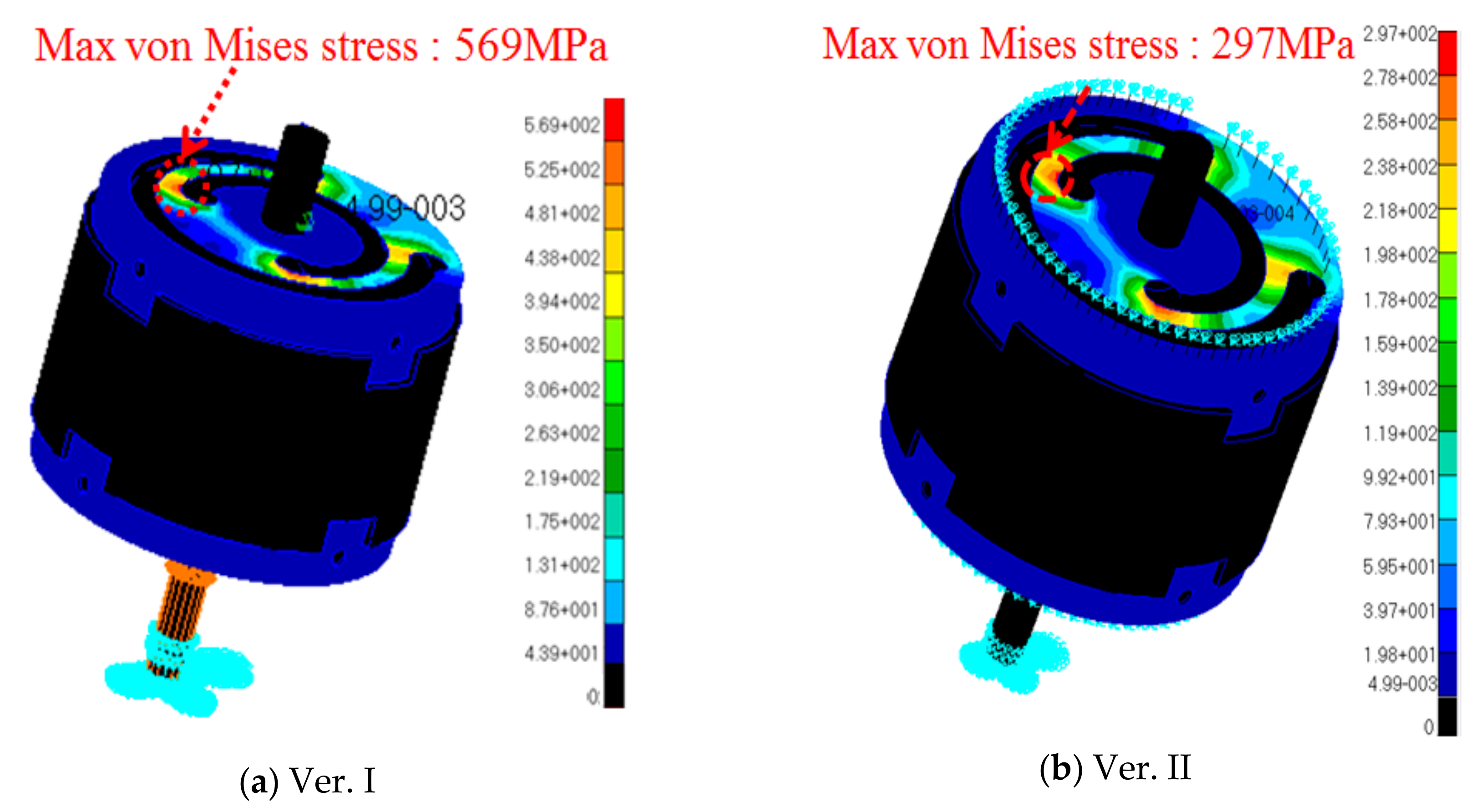
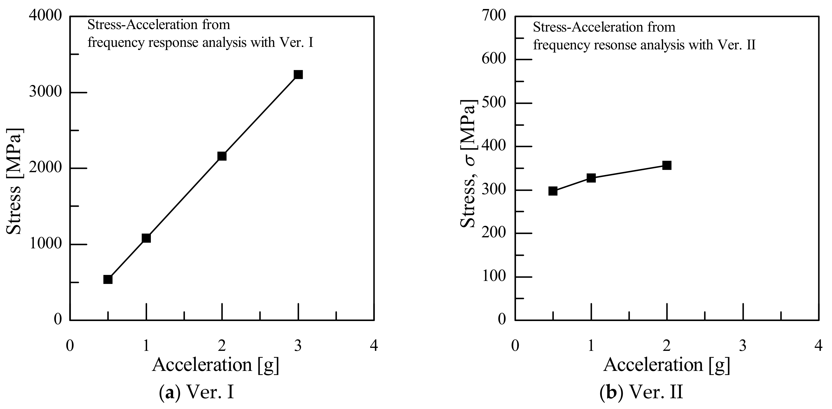
3.3. Results of the Frequency Response Analysis

As discussed above, the performance and structural integrity of VEHs should be studied taking into consideration the resonance between the excitation loads and VEHs. For this, the external loads should be defined in the frequency domain, and the structural response, taking into consideration the resonance, should be also expressed as the frequency response (a so called transfer function). The transfer function could be defined as the structural response per unit of external excitation load, for example acceleration at each frequency of interest [20]. From the frequency response analysis, the authors could obtain the stress, displacement, and acceleration response taking into consideration the resonance at hot spots (FCLs) in frequency domain.
Figure 10 shows the stress distributions on the leaf-spring shaped moving component for both Ver. I and Ver. II VEHs, respectively, under 0.5 g. The maximum stresses occur at the same locations, compared with the static FE analysis results in Figure 8. Their values and corresponding displacements may quite differ from the static FE results due to the resonance in frequency response analysis. For further understanding, the experimental results at the same points as shown in Table 3 are compared with these analysis displacement–frequency response results. Table 3 clearly shows that the experimental results are well matched with the analysis displacement-frequency response results for both the VEHs. It is, therefore, inferred that the frequency response analysis can describe well the response of the VEH in the frequency domain, which is impossible in the static analysis.
Using the above-verified frequency response analysis, the stress response at the FCL at various acceleration levels was analyzed; results are summarized in Figure 11. For Ver. I (Figure 11a), at its natural frequency, the stress at the FCL may reach almost 3,000 MPa when the applied acceleration is 3 g and this is much higher than the tensile strength of 1380 MPa of STS410, martensitic stainless steel. It can, therefore, be said that the Ver. I VEH is almost broken above acceleration of 1.38 g, which produces stress corresponding to the tensile strength [21].
On the other hand, the maximum stress of Ver. II VEH at the FCL is 356 MPa when the acceleration was 2g. This means that Ver II VEH could be operated safely at 2 g or even higher, which is much higher than the acceleration limit of 1.38 g for Ver. I VEH. The leaf spring-shaped moving component of Ver. II VEH was made from SKD 61 high strength hot work tool steel, whereas the moving component of Ver. II VEH was STS410. Although the SKD61 hot work tool steel has higher tensile strength than the STS410 martensitic stainless steel, the superior structural integrity of Ver. VEH comes from the structural feature of Ver. II VEH with the moving component displacement limited to 2 mm, as well as the higher tensile strength of SKD61 in Ver. II VEH.

4. Conclusions

In this study, the authors carried out a static performance test and static and frequency response analyses for two versions of vibration-based energy harvesters. Based on these results, the authors proposed a procedure to assess the structural performance and integrity for VEHs.
(1)
Static performance tests were performed via the incremental sinusoidal sweep test condition at the predefined frequency range and acceleration level.
(2)
We carried out static structural analysis to assess the natural frequency and failure critical locations (FCLs) on the leaf spring-shaped moving component of VEHs.
(3)
We performed frequency response analysis to identify the stress and displacement responses at the FCL in the frequency domain.
(4)
Based on these results, we investigated the structural performance and integrity of VEHs in two versions taking into consideration the resonance between the excitation load and the VEHs.

Author Contributions

Data curation, J.-W.J. and K.-W.K.; software, J.-W.J.; writing—review and editing, K.-W.K. All authors have read and agreed to the published version of the manuscript.

Funding

This work was supported by the National Research Foundation of Korea (NRF) grant funded by the Korea government (MSIT) (NRF-2018R1C1B6002221) and by the Korea Institute of Energy Technology Evaluation and Planning (KETEP) and the Ministry of Trade, Industry & Energy (MOTIE) of the Republic of Korea (No.20173010024950).

Conflicts of Interest

The authors declare no conflicts of interest.

References

  1. Hirakawa, K.; Toyama, K.; Kubota, M. The analysis and prevention of failure in railway axles. Int. J. Fatigue 1998, 20, 135–144. [Google Scholar] [CrossRef]
  2. Birajdar, H.S.; Maiti, P.R.; Singh, P.K. Strengthening of Garudchatti bridge after failure of Chauras bridge. Eng. Fail. Anal. 2016, 62, 49–57. [Google Scholar] [CrossRef]
  3. Shipurkar, U.; Ma, K.; Polinder, H.; Blaabjerg, F.; Ferreira, J.A. A review of failure mechanisms in wind turbine generator systems. In Proceedings of the 2015 17th European Conference on Power Electronics and Applications (EPE’15 ECCE-Europe), Geneva, Switzerland, 8–10 September 2015. [Google Scholar]
  4. Gomez, M.J.; Castejón, C.; Garcia-Prada, J.C. Automatic condition monitoring system for crack detection in rotating machinery. Reliab. Eng. Syst. Saf. 2016, 152, 239–247. [Google Scholar] [CrossRef]
  5. Kim, J.-H.; Lee, J.-Y. A Feasibility Study on the Energy Harvesting Technology for the Real-Time Monitoring System of Intelligent Railroad Vehicles. Trans. Korean Soc. Mech. Eng. B 2011, 35, 955–960. [Google Scholar] [CrossRef]
  6. Yoon, E.-J.; Park, J.T.; Yu, C.G. Power Management Circuits for Self-Powered Systems Based on Solar Energy Harvesting. J. Korea Inst. Inf. Commun. Eng. 2013, 17, 1660–1671. [Google Scholar] [CrossRef]
  7. Andosca, R.; McDonald, T.G.; Genova, V.; Rosenberg, S.; Keating, J.; Benedixen, C.; Wu, J. Experimental and theoretical studies on MEMS piezoelectric vibrational energy harvesters with mass loading. Sens. Actuators A Phys. 2012, 178, 76–87. [Google Scholar] [CrossRef]
  8. Roundy, S. On the Effectiveness of Vibration-based Energy Harvesting. J. Intell. Mater. Syst. Struct. 2005, 16, 809–823. [Google Scholar] [CrossRef]
  9. Frank, G.; Peter, W. Characterization of Different Beam Shapes for Piezoelectric Energy Harvesting. J. Micromech. Microeng. 2008, 18, 104013. [Google Scholar]
  10. Xu, R.; Borregaard, L.; Lei, A.; Guizzetti, M.; Ringgaard, E.; Zawada, T.; Hansen, O.; Thomsen, E.V. Preliminary Performance Evaluation of MEMS-based Piezoelectric Energy Harvesters in Extended Temperature Range. Procedia Eng. 2012, 47, 1434–1437. [Google Scholar] [CrossRef]
  11. Kim, J.E.; Kim, H.; Yoon, H.; Kim, Y.Y.; Youn, B.D. An Energy conversion model for cantilevered piezoelectric vibration energy harvesters using only measurable parameters. Int. J. PR. Eng. Man-GT. 2015, 2, 51–57. [Google Scholar] [CrossRef] [Green Version]
  12. Uzun, Y.; Kurt, E. Performance exploration of an energy harvester near the varying magnetic field of an operating induction motor. Energy Convers. Manag. 2013, 72, 156–162. [Google Scholar] [CrossRef]
  13. Patel, R.; Tanaka, Y.; McWilliam, S.; Mutsuda, H.; Popov, A. Model refinements and experimental testing of highly flexible piezoelectric energy harvesters. J. Sound Vib. 2016, 368, 87–102. [Google Scholar] [CrossRef]
  14. Chen, R.; Ren, L.; Xia, H.; Yuan, X.; Liu, X. Energy harvesting performance of a dandelion-like multi-directional piezoelectric vibration energy harvester. Sens. Actuators A: Phys. 2015, 230, 1–8. [Google Scholar] [CrossRef]
  15. Zambrano, O.A.; Coronado, J.; Rodriguez, S. Failure analysis of a bridge crane shaft. Case Stud. Eng. Fail. Anal. 2014, 2, 25–32. [Google Scholar] [CrossRef] [Green Version]
  16. Zhao, L.-H.; Zheng, S.-L.; Feng, J.-Z. Failure mode analysis of torsion beam rear suspension under service conditions. Eng. Fail. Anal. 2014, 36, 39–48. [Google Scholar] [CrossRef]
  17. Özsoy, S.; Çelik, M.; Kadıoğlu, F.S.; Kadioğlu, F.S. An accelerated life test approach for aerospace structural components. Eng. Fail. Anal. 2008, 15, 946–957. [Google Scholar] [CrossRef]
  18. Kang, K.-W.; Jin, J. Structural Performance Evaluation for Vibration-based Energy Harvester utilized in Railway Vehicle. In Proceedings of the MATEC Web of Conferences, Barcelona, Spain, 22–25 February 2018. [Google Scholar]
  19. MSC. Software, 2006, MSC. Patran and Nastran Users Guide; MSC: Geneva, Switzerland, 2012. [Google Scholar]
  20. Kim, J.-H.; Lee, D.-C.; Lee, J.-H.; Ham, Y.-S.; Kang, K.-W. Fatigue analysis of spot-welded automobile components considering fatigue damage-induced stiffness degradation in time and frequency domains. Int. J. Precis. Eng. Manuf. 2017, 18, 389–397. [Google Scholar] [CrossRef]
  21. Kim, J.-H.; Jin, J.; Lee, J.-H.; Kang, K.-W. Failure analysis for vibration-based energy harvester utilized in high-speed railroad vehicle. Eng. Fail. Anal. 2017, 73, 85–96. [Google Scholar] [CrossRef]
Figure 1. Flowchart for structural performance.
Electronics 09 00357 g001
Figure 2. Vibration energy harvester.
Electronics 09 00357 g002
Figure 3. Structural performance test setup.
Electronics 09 00357 g003
Figure 4. Strain gauges at moving component of vibration-based energy harvester.
Electronics 09 00357 g004
Figure 5. Measured displacement–frequency curve using sine dwell tests.
Electronics 09 00357 g005
Figure 6. Strain and stress–frequency responses of Ver. II energy harvester.
Electronics 09 00357 g006
Figure 7. FE model for basic Vibration-based Energy Harvester
Electronics 09 00357 g007
Figure 8. Stress contour of VEH via static FE analysis.
Electronics 09 00357 g008
Figure 9. Displacement distribution of VEH via static FE analysis.
Electronics 09 00357 g009
Figure 10. Stress contours of VEH through frequency response analysis.
Electronics 09 00357 g010
Figure 11. Maximum stress response from frequency response analysis for VEH.
Electronics 09 00357 g011
Table 1. Mechanical properties.
.Young’s Modulus (GPa)Poisson’s RatioTensile Strength (MPa)Density (kg/mm3)
STS410203.100.2913007.81 × 10−6
SKD61205.230.2919559.19 × 10−6
SM45C201.000.36-7.00 × 10⁻⁶
ABS8.000.38-4.10×10⁻⁶
Neodymium Magnet180.000.30-7.20 × 10⁻⁶
Table 2. Relative error of modal analysis results with experimental results [%].
Ver. IVer. II
Relative Error [%]−1.502−0.106
Table 3. Relative error of frequency response analysis results with experimental results [%].
Ver.AccelerationExperimentalAnalysisError (%)
Ver. I0.5 g2.1 mm2.3 mm9.5
1 g3.2 mm3.4 mm5.8
Ver. II0.5 g1.2 mm1.3 mm7.6
1 g1.4 mm1.5 mm6.6

