1. Introduction
Microwave remote sensing of buried objects with the ground penetrating radar (GPR) has important applications in several fields, such as civil engineering (e.g., for the detection of pipes and utilities), geophysical analysis of the subsoil (through the inspection of roads and buildings), archeology [
1,
2,
3]. Other interesting applications are in the through-wall (TW) radar, where microwave fields are used for the detection of concealed weapons or humans in buildings’ interiors [
4]. The use of microwave fields for non-destructive diagnostic has an enormous potential, but there are still important limitations in terms of a fast and reliable target reconstruction. Whereas the field scattered by metallic targets can be quite easily isolated, the detection of many typical targets of GPR analysis, such as buried plastic pipes or subterranean cavities, is particularly hard due to the low permittivity contrast with the hosting medium. The scattered signals are generally weak and noisy, which makes direct interpretation of GPR images still challenging. Therefore, in experimental campaigns with GPR and TW radar, a theoretical and numerical modelling of the scattering by target and the surrounding environment plays an important role. This may be accomplished, for example, through a direct comparison of simulated data with measured radargrams [
5]. Otherwise, numerical results may be used as input data in of inversion and imaging algorithms, to assess the validity of the reconstruction scheme [
6,
7,
8,
9].
Two GPR architectures are mainly used: a frequency-domain solution, where the scenario is probed at a limited number of frequencies [
10,
11], in a stepped-frequency mode; a time-domain modality, with a pulsed signal excited by a wideband or ultrawideband source [
12]. As to the frequency-domain GPR, both numerical and analytical methods have been developed [
13,
14,
15,
16,
17,
18,
19,
20,
21,
22,
23,
24,
25] to model the scattered field by buried objects in a 2D layout with a monochromatic source. With a pulsed GPR, the radargrams are displayed in the form of A-scans, when the field is collected at one receiving point, or B-scans, when it is probed by a set of receivers. The finite-difference time-domain (FDTD) technique [
26], being directly implemented in the time domain, is mainly employed [
27,
28,
29] for the modelling of time-domain GPR surveys. In Reference [
29] a 3D electromagnetic simulation software designed for GPR applications, namely, gprMax, is proposed. Reconstruction algorithms, such as fitting techniques applied to the hyperbola displayed in the B-scan radagrams to determine size and depth of the target, can be validated on synthetic data returned by numerical modelling [
5]. FDTD is also employed by GPR users in several experimental works, to validate the measured radargrams against simulated data [
30], or in constructing data sets for target classification [
31]. Method-of-moments approaches [
32,
33,
34,
35] are also developed, where the scattered field is evaluated at sampled frequencies of the source spectrum, and the time-domain response is reconstructed through an inverse fast Fourier transform. A further numerical approach to the time-domain modelling of buried objects is given by the time-domain finite-element, as implemented in [
36].
In this paper, the time-domain cylindrical wave approach (CWA) is presented as a full-wave method to model GPR applications for the scattering by buried cylindrical targets with pulsed source fields. In its basic and original formulation, the CWA is a semi-analytical method for the frequency-domain analysis of the field scattered by buried targets with a monochromatic source [
19,
37,
38,
39,
40,
41,
42,
43]. The canonical layout assigned to the targets, i.e., circular cross-section cylinders, is representative of a wide class of objects, as pipes, tubes, or cables, investigated in the analysis of the sub-soil for localization of buried services. The use of an analytical approach is advantageous, in term of accuracy of the solution and computational times, compared to purely numerical techniques. For example, in the case of FDTD, the 2D investigation domain is discretized into square unit cells, and the circular boundary of the target is approximated through a staircase profile with less accuracy of the results. Moreover, in the CWA, solution is found applying boundary conditions at the cylinders’ interface, thus avoiding any discretization of the domain. With the FDTD, this may become time-consuming when a large environment is simulated, as in the case of deeply buried targets.
The analytical formulation of CWA stems on the use of cylindrical waves as basis functions to express the scattered fields [
44]. Since buried cylinders are placed below one or more flat interfaces, cylindrical waves are defined through plane-wave spectra, which allow dealing with reflection or transmission of the scattered fields by the interfaces. A preliminary work on a time-domain approach with the CWA is proposed in [
45]. In Reference [
46], the CWA is rigorously developed as a time-domain technique, solving the scattering problem of a pulsed plane-wave excitation field by perfectly conducting cylindrical targets buried in a semi-infinite half-space. The approach proposed in [
46] is completely spectral, as the source field is expressed through its plane-wave and temporal frequency spectra, and reconstructed in space and time through a double inverse Fourier Transform. In Reference [
47], the formulation proposed in [
46] is applied to a source field non-uniform in time and space in the range of optical frequencies.
The time-domain CWA presented in [
46] is here extended to a more realistic case, and a line-current source is used to model the illumination field excited by the transmitting antenna of the GPR equipment. Moreover, the general case of dielectric targets with frequency-dispersive permittivity is considered through a complex permittivity satisfying the Debye law [
2]. This represents a significant improvement in the simulation capabilities of the CWA since, in the microwave frequency range considered in GPR analysis, natural media exhibit a frequency dispersive behavior, due to the presence of water.
The paper is organized as follows: in
Section 2, the theoretical approach, applied to a line-source excitation, is presented. In
Section 3, numerical results are reported.
2. Theoretical Approach
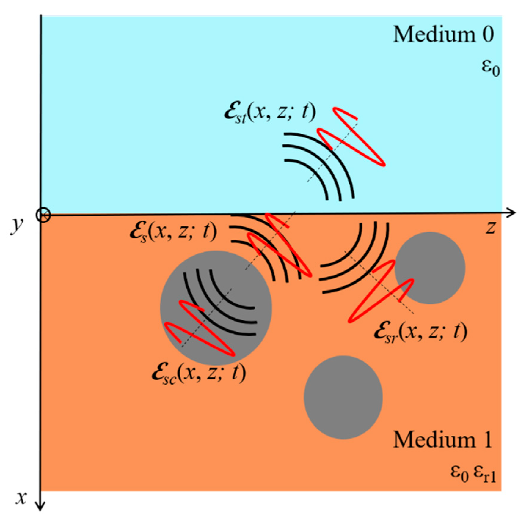
The geometry of the problem is reported in
Figure 1. The domain of analysis is divided into two regions: medium 0 (air,
), where a line-current source is located, and medium 1 (relative permittivity
), where
N dielectric cylinders are buried. The model is two-dimensional, assuming the length of the targets is much longer than the size of their cross-section, and then their mutual distances.
Beyond a main reference frame of rectangular coordinates (
x,
z),
N reference frames (
xp,
zp) centered on the axis of the
p-th cylinder (
p = 1, …,
N) are also introduced. The
p-th cylinder, of relative permittivity
, has radius
ap and center in (
hp,
dp), being
x =
xp +
hp, and
z =
zp +
dp. A polar reference frame (
r, q) is also employed, as well as
N polar reference frames (
rp, q
p) centered on the cylinders. The line source is placed along the axis
x = hL( < 0),
z = dL. The reference frame (
xL,zL), centered on the line source, will also be used, with
Since the line source is along the y-direction, we use the scalar function E(x,z; t) to represent the space and time dependence the electromagnetic field, that is parallel to the cylinders’ axis (TM, or E, polarization).
The source of the scattering problem is a downward propagating pulsed field in medium 0, incident on the interface between medium 0 and medium 1. The incident field is expressed through an inverse Fourier transform with respect to space and time [
46], that is
where
is the amplitude of a typical monochromatic plane wave in the expansion, and
is the parallel component of the wavevector of the typical plane wave, defined as
.
Furthermore, we assume that the amplitude can be written as
In Equation (3),
and
are the space and time spectra, respectively, and they are found through inverse Fourier transforms of the temporal waveform
and the spatial distribution
of the incident field, as
When the radiated field by the GPR transmitter can be modelled through a filament dipole antenna, i.e., a line-current source, the analytical expression of the radiated field is a cylindrical wave, described by a Hankel function of the first kind and zero order [
48]:
For propagation in the half space
, the spatial spectrum
relevant to the cylindrical function in Equation (6) is [
40]:
From the definition (7), applying the change of coordinates (1) to a line source centered in (
hL,
dL), the space distribution of the incident field can be described in terms of its plane-wave spectrum through the following expression:
that is equivalent to the definition of
given in (6).
The pulsed field in (2) is derived from (8) by assigning a frequency spectrum , that can be chosen among the temporal waveforms typical of the GPR analysis.
When the incident field impinges on the interface in x = 0, two fields are excited, in the absence of the cylinders: the reflected field
and the transmitted field
. As one or more dielectric targets are buried in Medium 1, a set of scattered fields by the cylinders is also excited, given by the following contributions (
Figure 2):
: fields scattered by the cylinders in Medium 1;
: scattered-reflected field in Medium 1;
: scattered-transmitted field in Medium 0;
: scattered field transmitted inside the p-th cylinder.
In the proposed approach, all the fields contributions will be expressed in terms of their spatial dependence through their plane-wave spectra, as was done in (8) for the incident field, and treated as monochromatic terms. The time-domain dependence relevant to a pulsed source field will be reconstructed through an inverse Fourier transform, analogous to the one in (2), having assigned to each frequency a spectral amplitude relevant to the frequency spectrum
, as will be explained in
Section 3.
As to the reflected field
, it is found from the spectral definition of the incident field in (8). Evaluating for each plane wave of the spectrum the corresponding reflected plane wave, through the Fresnel reflection coefficient and suitable wave-vector, the space-dependence of the reflected field can be expressed as follows [
40]:
where, according to the Snell’s law, the wavevector of the generic reflected plane wave of the spectrum in (9) is
and
is the Fresnel reflection at the interface between medium 0 and medium 1.
In a similar manner, the space dependence of the transmitted field is derived from the following expression:
where
is the wave vector of the typical transmitted plane-wave, and
is the Fresnel transmission coefficient at the interface between medium 0 and medium 1.
The expressions of the scattered fields shown in
Figure 2 are now recalled. The scattered field by the cylinders in Medium 1 is expressed as a sum of cylindrical waves
through unknown expansion coefficients
:
The choice to expand the scattered field in terms of cylindrical waves
in (11) is aimed to providing a solution to the scattering by circular cross-section cylinders on an analytical basis. Indeed, such functions are proportional to first-kind Hankel functions of order
m, , times the angular factor
:
In the frame of the employed spectral approach, the
m-th order cylindrical waves
are expressed alternatively through a plane-wave spectrum, as follows [
44]:
which corresponds to the expansion in (9), but for the
m-th order. The definition of the spectrum
of the
m-th order function is:
The spectrum (14) generalizes the definition (7), introduced for a zero-th order cylindrical wave, and is referred to both up- or down-propagating waves.
The definition of cylindrical waves (14) in terms of their plane-wave spectrum can be used to derive the two scattered fields contributions relevant to the interaction with the interface, i.e., the scattered-reflected field
and the scattered transmitted field
. In particular, basis functions dealing with reflection or transmission of the cylindrical waves are obtained by multiplying their spectra for the suitable reflection or transmission Fresnel coefficient, respectively, and the relevant propagation term. The resulting cylindrical waves of
m-th order are called reflected cylindrical waves
:
and transmitted cylindrical waves
:
where
in (15) and
in (16) are the Fresnel reflection and transmission coefficients, respectively, applied to up-propagating waves of the spectrum (13).
Employed as basis functions, (16) allows us to define the scattered reflected field:
As to the scattered-transmitted field in air, it is expressed through the basis functions (16):
In the case of dielectric targets of relative permittivity
, a scattered field contribution transmitted inside the cylinders is also excited. It is represented through an expansion in first kind Bessel functions
and a second set of unknown expansion coefficients
:
Now, the expressions of the fields (10), (11), and (17) are arranged in polar coordinates in the reference frames centered on the axis of the
q-th cylinder, in a form more suitable to impose boundary conditions on the circular boundaries of the cylinders. Applying the expansion of a plane-wave into Bessel functions [
19], for the fields (10), (11), and (17) it is obtained, respectively:
In Equation (20), the term
is given by the following spectral function [
40]:
whereas expression (21) has been found making use of the addition theorem for Hankel functions [
49].
Finally, boundary conditions on the total electric field and its redial derivative are imposed on the cylinders’ interface, as, respectively:
with
p = 1, …,
N, where, in the case of perfectly conducting cylinders, the second member of the conditions (24) and (25) reduces to zero. Equations (19)–(22) are replaced in (24) and (25), and after some algebra a linear system is obtained for the expansions coefficients
:
where the superscripts
1,2 refer to the boundary conditions (24) and (25), respectively, and it is
,
, with:
being
,
, and
,
, where
.
The coefficients
, relevant to the scattered field transmitted inside the cylinders, are found from:
When the targets are perfectly conducting cylinders, the final system has the same form as in (27), with that corresponds to the matrix in (27), and to the term in (28) with = 1.
3. Results
The approach presented in
Section 2 has been turned into a numerical code to solve the scattering by targets in GPR applications. The issues already highlighted in [
46], such as the truncation rule of the system (26) and the numerical evaluation of the spectral integrals, are applied.
The excitation from the pulsed field in (2) employs a frequency spectrum
s(
f) evaluated as inverse Fourier transform of a temporal waveform, according to (4). As possible waveforms, the typical ones of the GPR sources can be modelled [
46], among which the most common choices are the Gaussian waveform or its first and second derivatives [
50]. In the following examples, the second derivative of a Gaussian waveform is used, namely,
where
is the duration of the pulse, given by
. In the following simulations, Equation (30) is evaluated assigning a time delay
T, related to the central frequency
f0 of the spectrum through
T = 1/
f0.
The time-domain implementation of the CWA is carried by sampling the spectrum
s(
f) assigned to the source field in (2) at the frequencies
fk, with
k = 1, …,
Ns. As the
k-th frequency sample of the incident field is given by:
Equation (31) is used as the field of the
k-th monochromatic sources of the scattering problem. Therefore, the system (26) is solved at the
Ns sampled frequecies to find the scattered-transmitted field in air at each sampled frequency:
The time-domain field contribution is finally reconstructed from (32) through an inverse fast Fourier transform (IFFT) [
51]:
where
Df is the frequency step chosen in the sampling, and the number of samples
Ns is taken as an integer power of 2, according to the FFT and IFFT rules.
An example of radargrams from a dielectric cylinder of relative permittivity
= 7, buried at a depth
h = 50 cm in a soil of relative permittivity
= 4 is considered. As displayed in the scheme of
Figure 3, the souce field and the probing point are scanned through a line of length
Ls, parallel to the interface, in a bi-static approach. The horizontal distance between transmitter and receiver is
= 10 cm. The transmitter is moved from z
L = −80 cm to z
L = 60 cm, and the receiver from z = −70 cm to z = 70 cm, with a total scanning distance
Ls = 1.4 m and 41 positions. Transmitters and receivers are placed along the line
xL = −5 cm. The excitation pulse has a temporal waveform given by Equation (30) evaluated at the central frequency
f0 = 600 MHz . Two radargrams are shown in
Figure 4 in the form of a B-Scan, displaying the scattered field by the target at the receiver points as a function of time, for a target radius
a = 5 cm (
Figure 4a), and in
Figure 4b for
a = 10 cm. In the reported example, the B-scans show a first hyperbola relevant to the scattered field from the top of the target, followed by a second one, showing a strong scattering from the internal side of the cylinder. Two further hyperbolas, of weaker intensity, that are relevant to high-order reflections of the earlier hyperbola, are displayed at a later arrival time.
A scheme of the possible path lengths experienced by the pulse in the lower medium are displayed in
Figure 5a, and include: the zero-th order term of straight propagation between the top of the cylinder and the interface (labelled with t
A) or inside the cylinder (t
B); higher-order reflections between the top of the cylinder and the interface (t
D, t
E and t
G) or inside the cylinders (t
C); multiple reflections in both regions (t
F). According to the scheme in
Figure 5a, arrival times with a cylinder of radius
a = 5 cm are given by: t
A = 8 ns, t
B = 9.7 ns, t
C = 11.5 ns, t
D = 14 ns, t
F = 15.7 ns, t
6 = 20 ns, and t
G = 17.5 ns. These arrival times are highilighted in the A-scan of
Figure 5a, except for the time t
F that is of extremely low amplitude. With a radius
a = 10 cm temporal distances between pulses relevnt to scattering from the front side of the cylinder and its backside are more delayed, due to the double target size. Arrival times are t
A = 7.3 ns, t
B = 10.1 ns, t
C = 14.4 ns, t
D = 12.7 ns, t
E = 16.2 ns, t
f = 19.7 ns, and t
G = 18 ns. The presence of echoes relevant to multiple interactions of the the target with the interface and multiple reflections inside the target proves the accuracy of the theoretical approach and its numerical implementation.
The presented approach allows modelling the constitutive material of the target as a frequency-dispersive medium. For example, a dispersive permittivity model satisfying the Debye law may be employed [
2]:
where
is the static dielectric constant of the relative permittivity,
is the high-frequency limit of
, and
is the relaxation time, that can be related to the relaxation frequency
fr through
. The Debye law (34) provides the frequency dependence of pure water. Most of natural materials, such as rocks and soil, are mixtures of the bulk material with water and air. Due to the large permittivity contrast between the bulk material and water, especially at frequencies below 10 GHz, the dielectric permittivity of natural materials is strongly dominated by water, and the resulting permittivity of the mixture may be still described by the Debye formula (34). In the first example relevant to the Debye law, the target filling material is pure water with permittivity parameters
= 80,
= 4.9, and
= 9.3 × 10
−12 s; radius of the target is
a = 10 cm and depth
h = 50 cm. The time waveform in (30) is evaluated at the central frequency
f0 = 1 GHz. The scanning parameters are the same as in the earlier example of
Figure 4. In the results in
Figure 6, the B-scan evaluated with the CWA is also compared to the one from gprMax V3 [
29], with a very good agreement. In the shown time-window, three hyperbolas are displayed, where the earliest is relevant to the scattering from the top of the cylinder, followed by the scattering from its backside, and finally by the reflection of the first field contribution by the interface.
A further example of target with dispersive permittivity approximated with a Debye model is given in
Figure 5, where a clay cilinder of radius
a = 10 cm buried at a depth
h = 50 cm is simulated. The permittivity of the clay target is modelled through a general Debye model with multiple relaxation times
(
k = 1, …,
N), and including also the electrical conductivity
, as follows:
In the results, three different electrical and dielectric parameters are used in (35) for the evaluation of the B-Scans of
Figure 7: (a) constant parameters
= 2 and
= 0.137 S/m; (b) one Debye relaxation (
N = 1) with
= 24.07,
= 2,
= 8 × 10
−12 s, and
= 0.137 S/m; (c) three Debye relaxations (
N = 3), with
= 19.99,
= 5.47,
= 24.07,
= 2,
= 4.83 × 10
−9 s,
= 4.41 × 10
−10 s,
= 8 × 10
−12 s, and
= 0.038 S/m [
52]. In the plots, a similar behavior in the hyperbola relevant to the scatting from the front side of the cylinder is displayed, whereas a progressive reduction in the amplitude of the later hyperbolas is visible with one and three relaxations. These effects are compared in the A-scan of
Figure 7d, which is relevant to the scattered field probed at the receiving point in
Ls = 70 cm (receiver #21), aligned above the cylinder. The amplitude of the field with the three-relaxations model is more than halved in the first pulse, and of very low amplitude in the later echoe relevant to the scattering from the backside of the target, due to the high absorption introduced by the target filling material. The example shows the effectiveness of a model with frequency dispersive materials in the simulation of GPR targets.

