1. Introduction
Medium Frequency Transformers (MFTs), associated with DC-DC converters, require the highest possible power density, high efficiency, and a specific dispersion inductance at the lowest cost. Regarding this inductance, a precise knowledge of the value of this parameter is critical to set the power control range of a DC-DC DAB-type converter. To properly operate, this converter requires a minimum value of dispersion inductance at its input port. The dispersion inductance of the MFT is part of this minimum inductance. The other part is provided by an inductor external to the MFT.
In recent years, MFTs have gained more attention [
1,
2,
3,
4], mainly because of their use in DC-DC DAB-type converters [
5,
6,
7,
8]. On the other hand, in power electronics applications, there have been advances in using a new type of semiconductor materials for the devices. These materials include Gallium Nitride (GaN), Silicon Carbide (SiC) and Gallium Oxide. These materials are expected to play an essential role in power electronics devices due to their intrinsic characteristics such as a much higher breakdown voltage and conversion efficiency [
9,
10,
11,
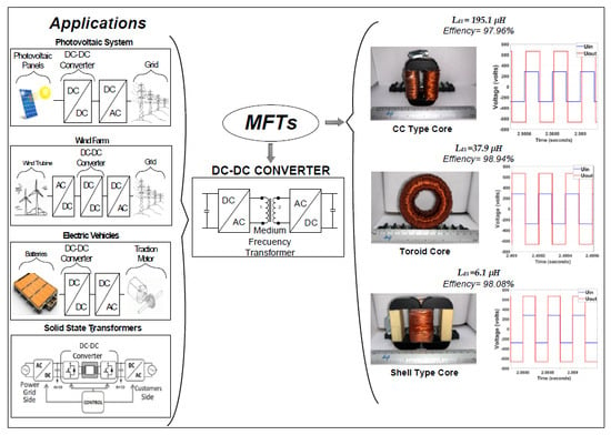
12]. MFTs in electronic converters are used as interfaces for the interconnection of medium-scale renewable power sources [
13] to electric grids, solid-state transformers [
14] and electric vehicles [
15].
The MFT has been studied from various points of view: (1) noise performance, considering analysis and tests of vibrations and audible noise with toroidal cores and type CC [
16]; (2) electric field study, which highlights that by using litz wire in the secondary winding, compared with foil conductor, a smaller maximum electric field intensity can be achieved [
17]; (3) analysis of core manufacturing of MFTs carried out by different companies [
18]. In this case, about 15 samples of each core, with similar characteristics, are taken, and the accuracy of the measurements, including losses in the core, are verified with physical prototypes; (4) loss calculation [
19] by means of a new empirical calculation method based on the Steinmetz equation. Regarding design procedures, currently there are various methodologies for designing MFTs [
1,
2,
3,
4,
20]. Each methodology proposes the use of a different geometry, opting between toroidal [
1,
20], shell type [
2,
4], or CC type [
3], and different materials at specific range of frequencies; for example, silicon steel at 600 Hz and 1 kHz [
3,
21], nanocrystalline alloys at 1 and 5 kHz [
20,
22], and ferrites at 20 kHz [
2]. The purpose of each design methodology is to achieve a high efficiency, and high power density at a low construction cost. However, among the most recent publications there are few papers presenting experimental validations with physical MFTs along with comparing the characteristics and performances obtained with each core geometry.
The need to get the minimum value of the dispersion inductance with a smaller inductor external to the MFT, for attaining full control of DC-DC DAB-type converters [
4], has advanced the development of MFTs with different geometries in the interest of better understanding the dispersion inductance obtained with each geometry, as well as the MFT efficiency, power density, core losses and winding losses achieved. The new knowledge thus attained can facilitate the selection of the best-performing geometry in MFT cores for a given operating condition. To date, it is not known which geometry results in better features in MFTs applied to DC-DC DAB-type converters connected to modern distribution grids.
MFTs with a toroidal core have a relatively low dispersion inductance. This implies that less dispersed flows tend to have a higher efficiency [
1,
20]. Research on CC-type core [
3] and shell-type core [
2,
4] report high efficiency but give little information on the dispersion inductance. Regarding toroidal cores, currently there is a wide variety of sizes on the market, in contrast to the CC- and shell-type.
This research work aims to compare three core geometries (toroidal, CC- and shell-type) for designing and implementing MFTs, each one with a single type of geometry. This comparison is carried out with simulations and is verified experimentally using physical prototypes tested at the same operation conditions. All cores are of nanocrystalline alloy. As results, the advantages and disadvantages of each core geometry, highlighting the value of the dispersion inductance, are presented.
Contribution of this work: This work is a novel proposal that presents cutting-edge information about the comparison of physical prototypes of three MFT cores of different geometries (toroidal, type CC and shell-type) all operated at the same frequency and power. From the authors´ perspective, the fresh information brought by the results of this comparative study, which highlights the advantages and disadvantages of each geometry, can improve the design of MFTs with respect to the increase in power density and efficiency.
This paper is organized as follows:
Section 2 presents the methodology used for the design of the MFTs presented in this document.
Section 3 presents the geometries used in the core of MFTs, comparing their physical dimensions and the parameters obtained from the design.
Section 4 presents results of core losses, winding losses, design efficiencies, winding costs, core costs and total transformer cost.
Section 5 presents the simulation results of MFTs submitted with sinusoidal and square signals (DAB provides these).
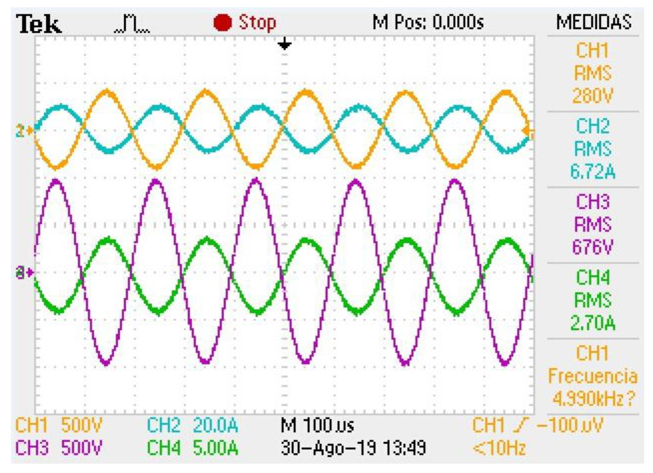
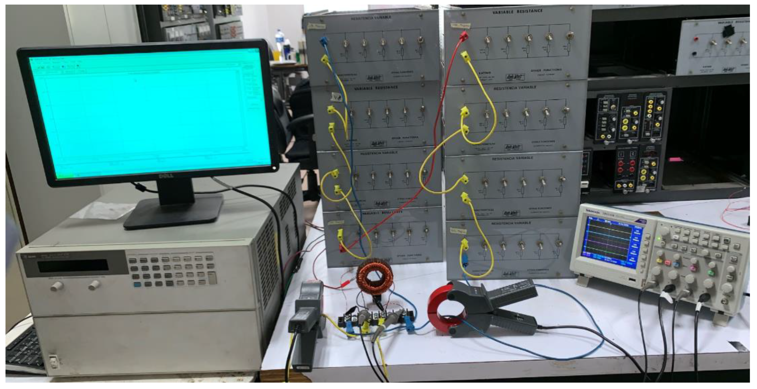
Section 6 presents the results of an experimental test with prototypes of MFTs using sinusoidal waves. Finally,
Section 7 presents a discussion of the results and
Section 8 the conclusions.
2. Design of MFTs
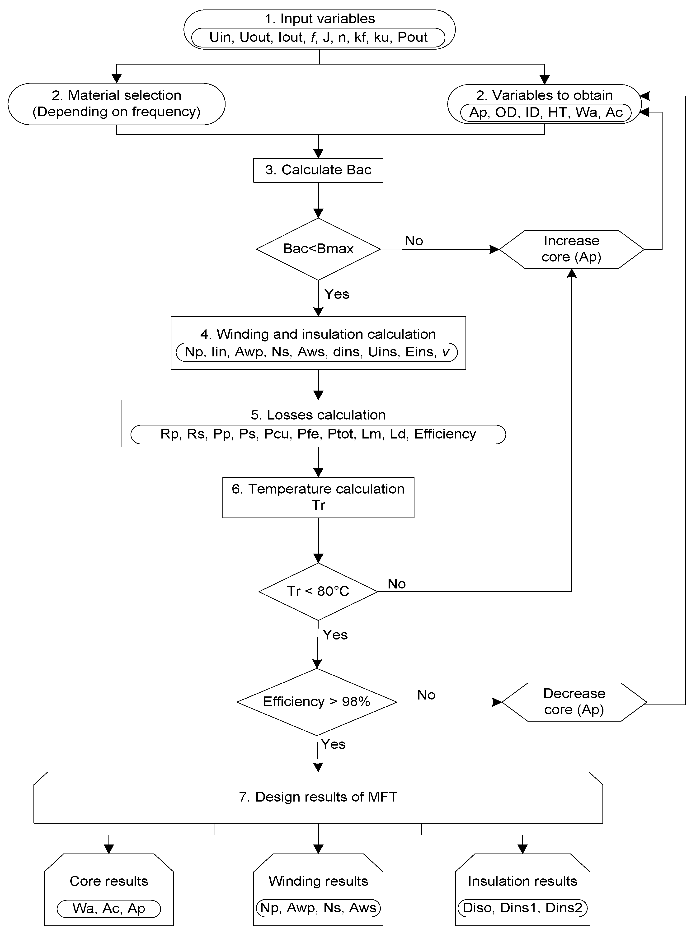
The methodology used for the design of the three MFTs with a nanocrystalline core is presented in [
20] and shown in
Figure 1. The selection of nanocrystalline material is due to its favourable characteristics for medium frequency operation [
23,
24], including a high efficiency and high-power density, compared to silicon steel [
3], ferrites [
2] and amorphous materials [
1].
In step 1 of the MFT design procedure, the initial values are selected: these are output power (Pout), output current (Iout), input voltage (Uin), output voltage (Uout), turns ratio (n), frequency (f), current density (J), waveform coefficient (kf), and window utilization factor (ku). In step 2, the core material is selected for the frequency of interest—in this case, nanocrystalline alloys. In step 3, the physical dimensions of the core are selected—in this case, for the three types of cores of interest, the window area (Wa), the effective cross-section of the core (Ac), and the product area (Ap). Si Bac < Bmax (1.2 T, for nanocrystalline case), follow step 4. Otherwise, increase Ap (Ap = Wa ∗ Ac) and repeat from step 2. In step 4, the primary winding turns (Np), the secondary winding turns (Ns), the input current (Iin), the primary wire area (Awp), the secondary wire area (Aws), the insulation dielectric rigidity (Eins), the minimum distance between conductors (dins), the required insulation voltage (Uins), and the safety margin (v) are all calculated. In step 5, the magnetization inductance (Lm), the dispersion inductance (Ld), the primary windings resistance (Rp), the secondary windings resistance (Rs), the primary windings losses (Pp), the secondary winding losses (Ps), the copper losses (Pcu), the core losses (Pfe), total losses (Ptot) are calculated. Finally, in step 6, the temperature (Tr) is calculated. If Tr < 80 °C and the calculation of efficiency is greater than 98%, then the final values of the design are obtained, such as core dimension, winding characteristics and insulation dimensions, where the insulation dimensions Diso are the distance between the primary and secondary winding, Dins1 is the minimum insulation distance between primary conductors and Dins2 is the minimum insulation distance between the secondary conductors.
3. Core Geometry for MFTs
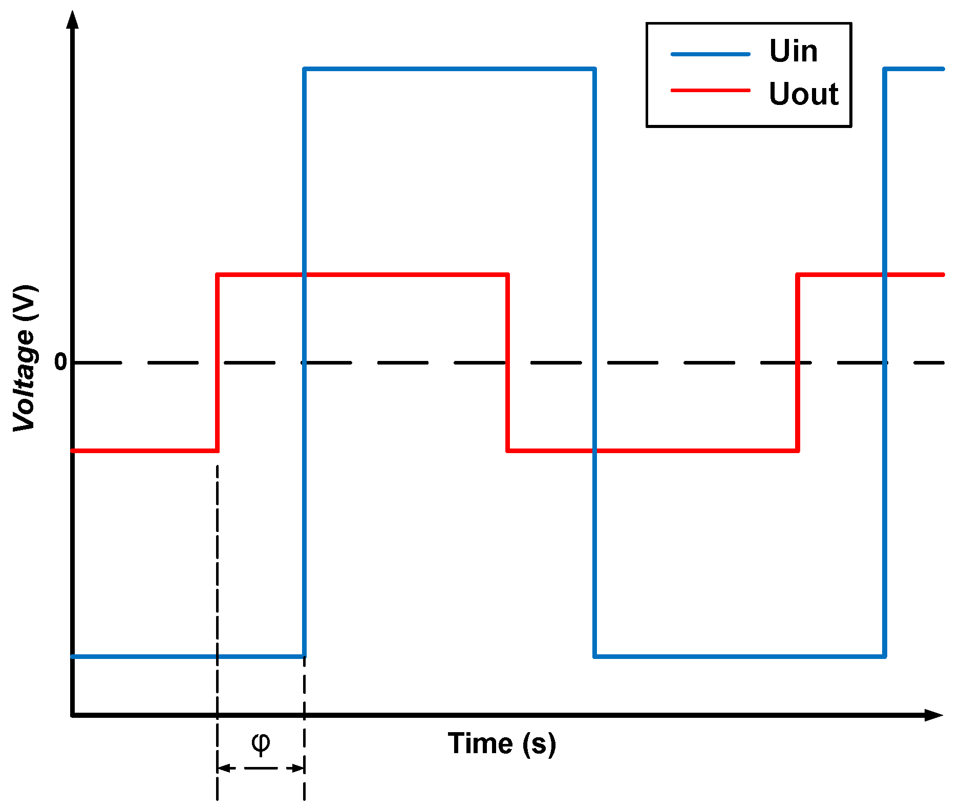
The geometry of the core of an MFT has a significant impact on defining the value of the dispersed flow value, efficiency and power density and is essential in the value of the dispersion inductance,
Ld. This value is of great interest to designers of DC-DC DAB-type converters due to its role in determining the control range of the output power of the converter. In order to achieve the control, this converter requires a minimum value of inductance to establish a phase shift, ψ, between
Uin and
Uout, as shown in
Figure 2. Commonly, the value of the dispersion inductance of an MFT is below that minimum value, therefore an inductor external to the MFT is needed. The lower
Ld, the higher the external inductance.
The value of the minimum dispersion inductance,
, needed to achieve ψ is given by Equation (1) [
4]
where
UDC1 and
UDC2 are the input voltage and output voltage of the DC-DC converter,
is the minimum phase shift between
Uin and
Uout,
Pout is the output power,
fs the operating frequency, and
n is the transformed ratio.
The designs published in the current literature focus only on MFTs, but not on the combined operation of an MFT and the DC-DC converter [
7,
20]. In some designs, the input and output voltage signals present only a minimum shift [
4,
20], different to the shift shown in
Figure 2. This represents a shorter control range of the output power of DC-DC DAB-type converters. The research on core geometries is carried out in order to identify the geometry with the best efficiency/power density/dispersion inductance relationship. With a better relationship, improved DC-DC converters, which are more efficient, with a higher power density and higher control range can be obtained.
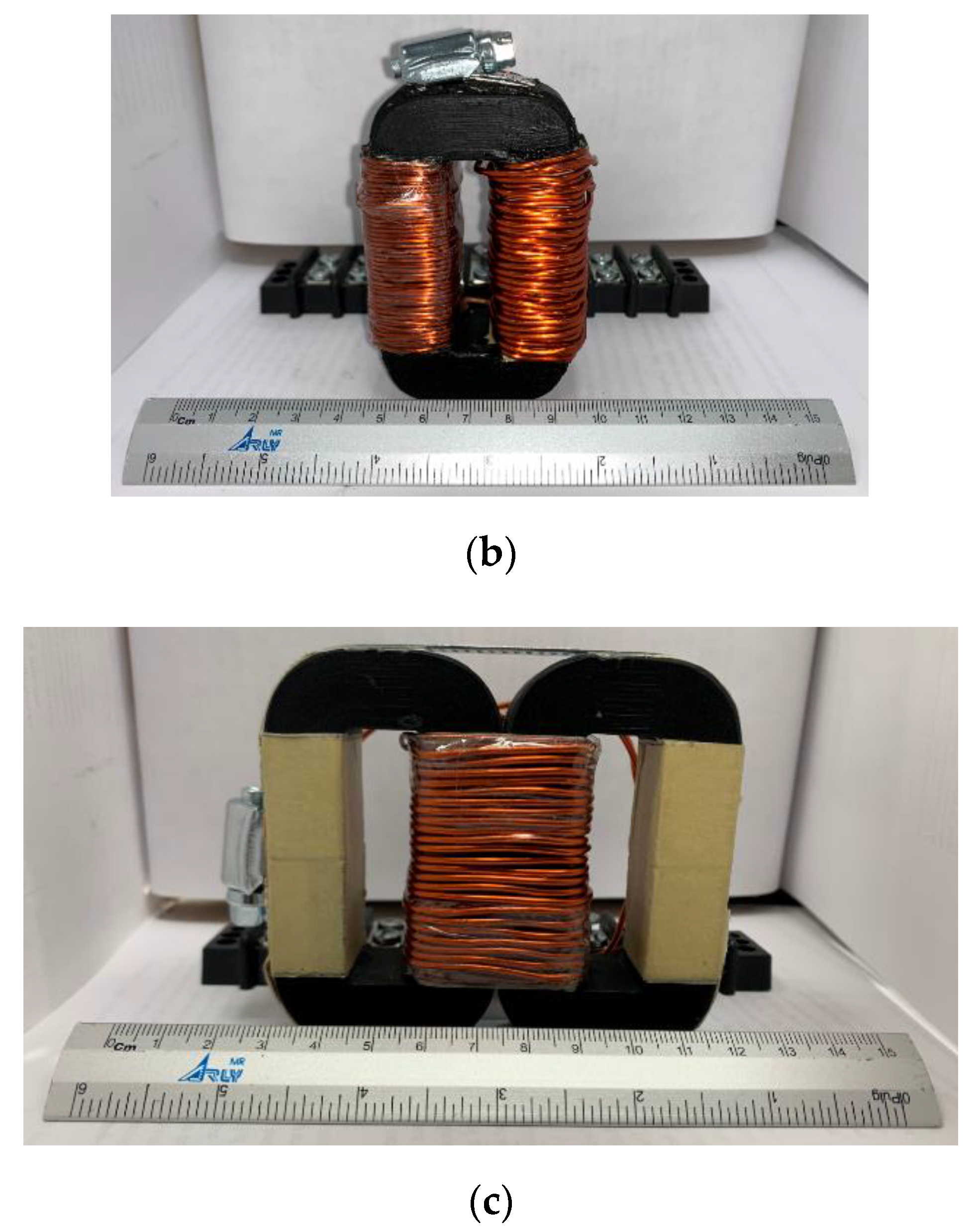
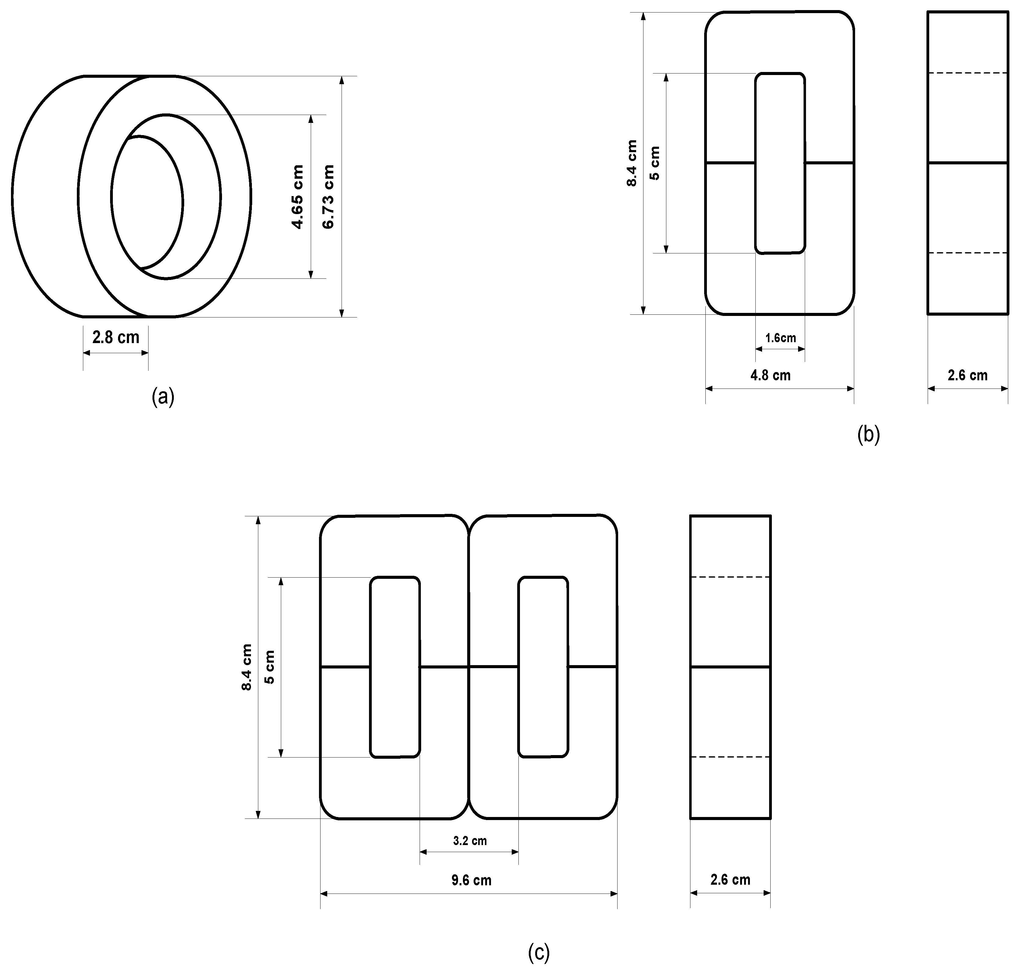
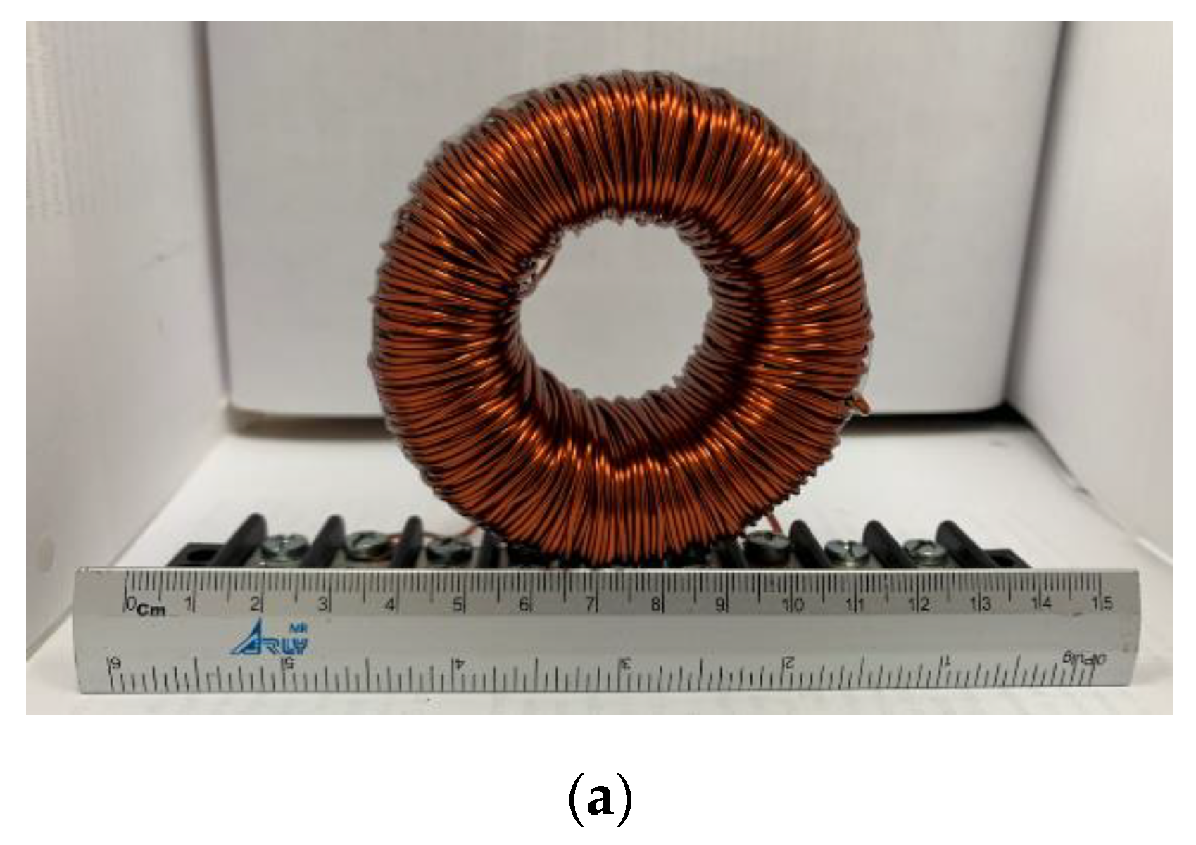
The dimensions of the three cores, one toroidal (MFT1), one type CC (MFT2), and one shell type (MFT3), one for each MFT, are shown in
Figure 3.
Table 1 presents the volume (
Vfe) and the weight (
Wfe) of each core.
Table 2 presents the design results of each MFT.
According to
Table 1, the MFT1 has the smallest volume, and the MFT3 has the largest. Also,
Table 2 shows that the MFT3 has a lower number of turns and the MFT1 has the highest.
4. Losses in Winding and Core
In MFT designs, it is always of interest to achieve high efficiency while keeping losses low. Core losses are associated with the type of core material, the material permeability, and the flow density, all defined in the MFT design. The losses in the medium frequency range have been reduced using nanocrystals and amorphous materials [
4,
20,
23]. In this work, the three cores are nanocrystalline.
This section presents the losses of the winding and the core calculated for each of the three MFTs using the method described in [
20].
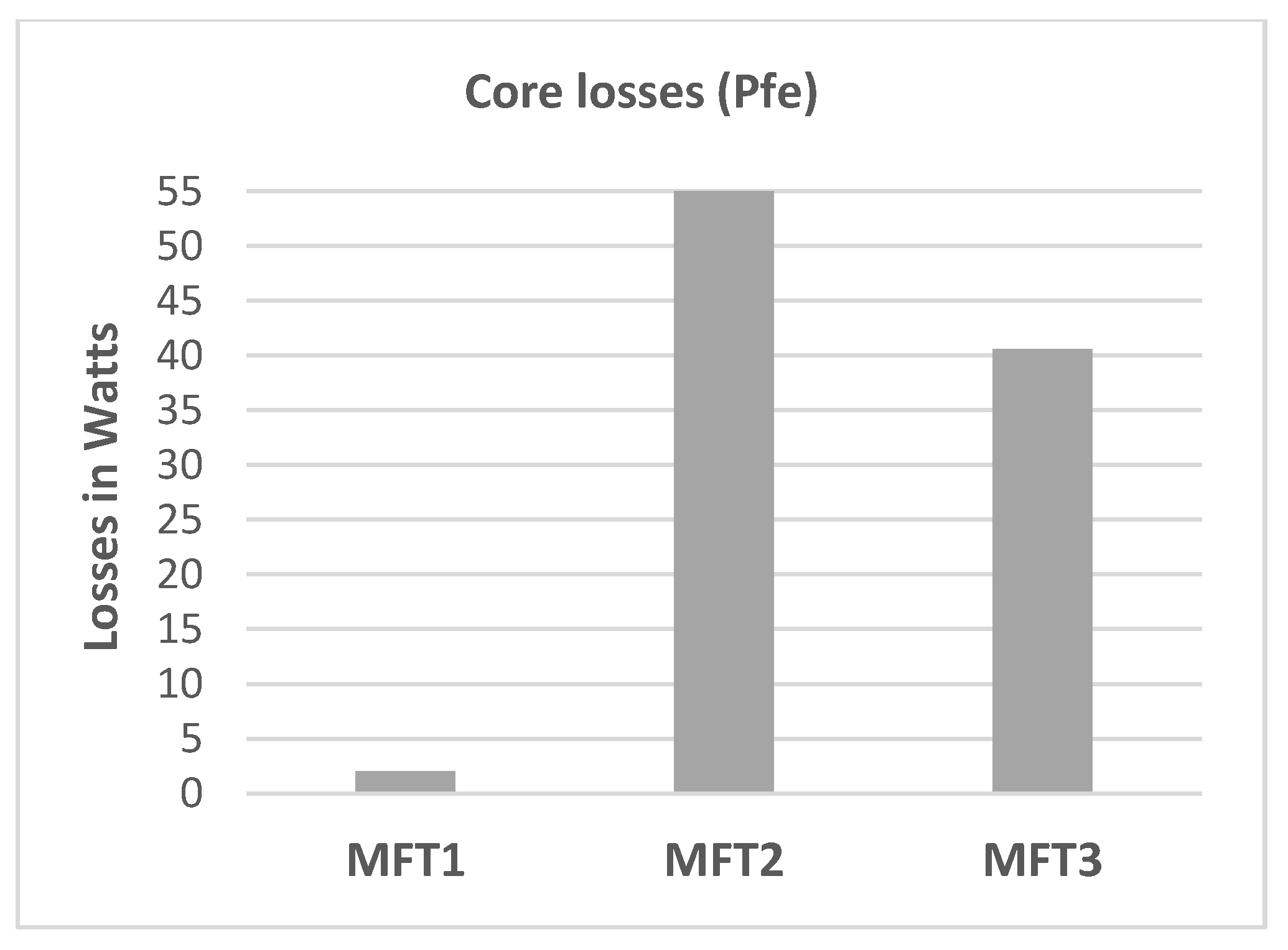
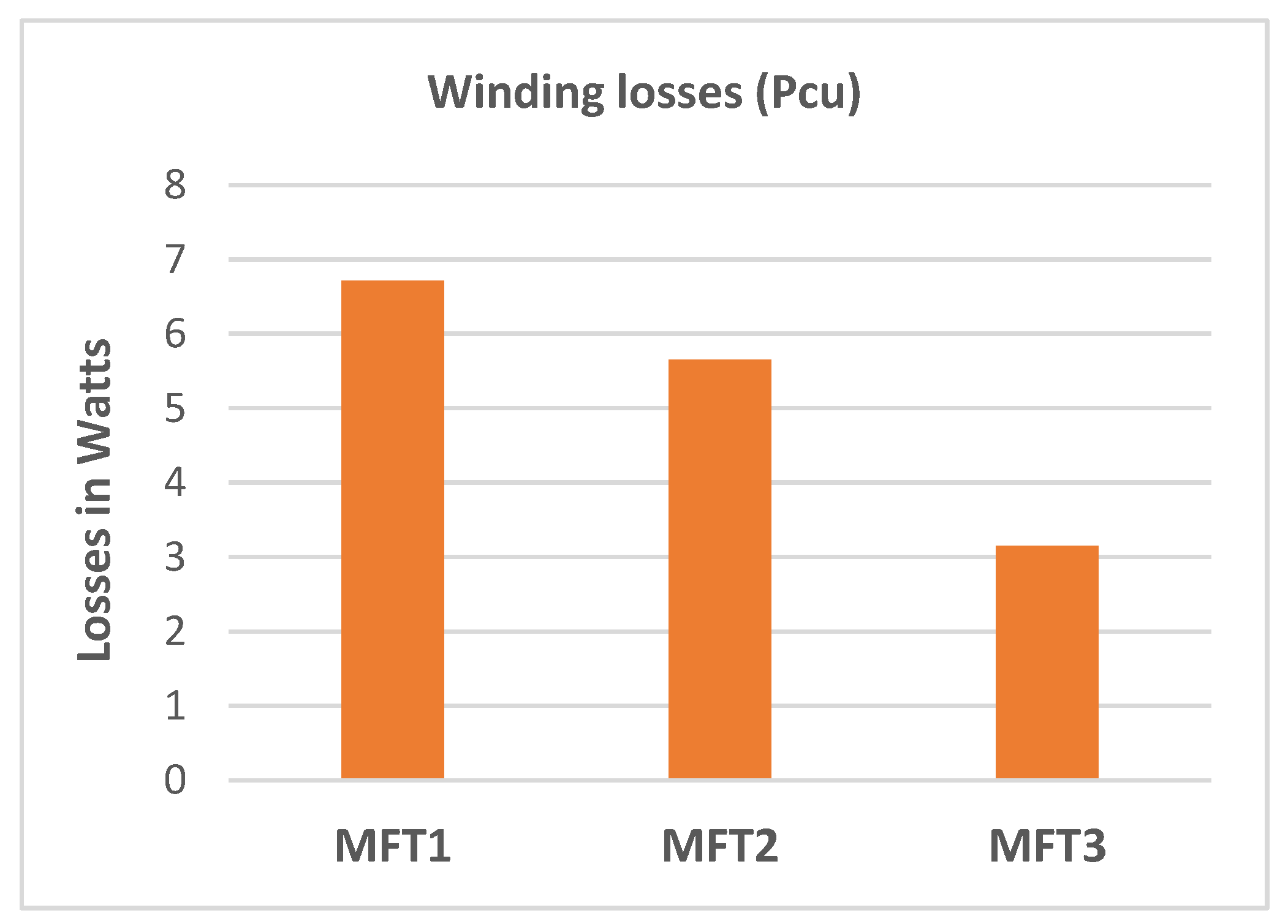
Figure 4 shows the losses in the winding and
Figure 5 the losses in the core of the three MFTs.
According to
Figure 4, MFT1 had the most significant losses in the winding, with 15.8% and 53% higher than MFT2 and MFT3, respectively.
Figure 5 shows the losses in the core. These are 27% and 96.3% higher in MFT2 and MFT3 than in MFT1, respectively.
The MFT1 has lower total losses due to the type of the core geometry and its lower dispersed flow. The latter means a greater confinement of the magnetic flux in the core. MFTs with CC-type core and shell-type have higher losses than MFT1. This is partly explained by the gap and increased dispersed flow due to the two-part structure of the cores, which results in higher losses [
16].
Table 3 shows the values of core losses and losses in the winding of the three MFTs.
Table 4 shows the efficiency of these MFTs.
The validation of the results of
Table 3 and
Table 4 are presented in
Section 6, using the results obtained from three experimental prototypes. The essential cost of the three MFTs is presented in
Table 5.
According to
Table 5, the core of the MFT1 has the lowest total cost even when its winding cost is higher, due to the low cost of its core. The core cost of the MFT2 is lower than that of the MFT3, but the winding cost is higher because the MFT3 is built with two CC cores and the MFT2 is built with only one CC core. The MFT3 is a higher cost transformer, mainly due to the core of the MFT.
5. Simulations
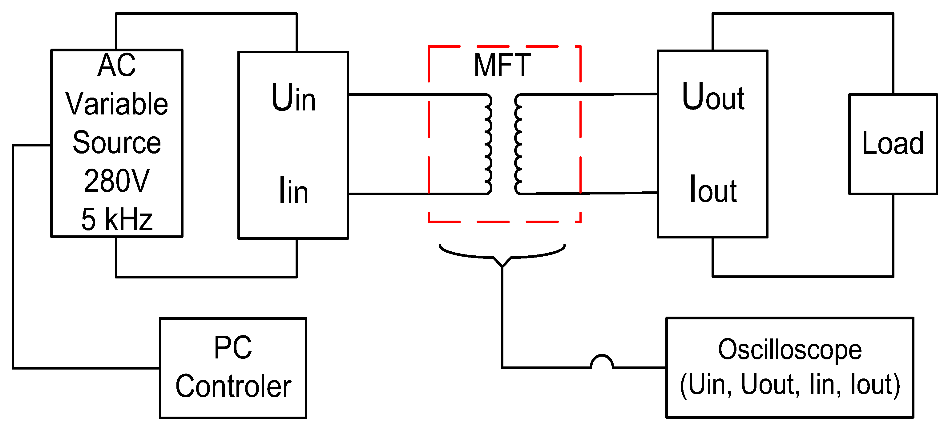
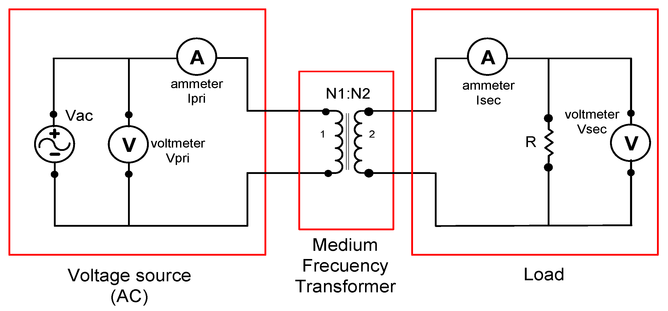
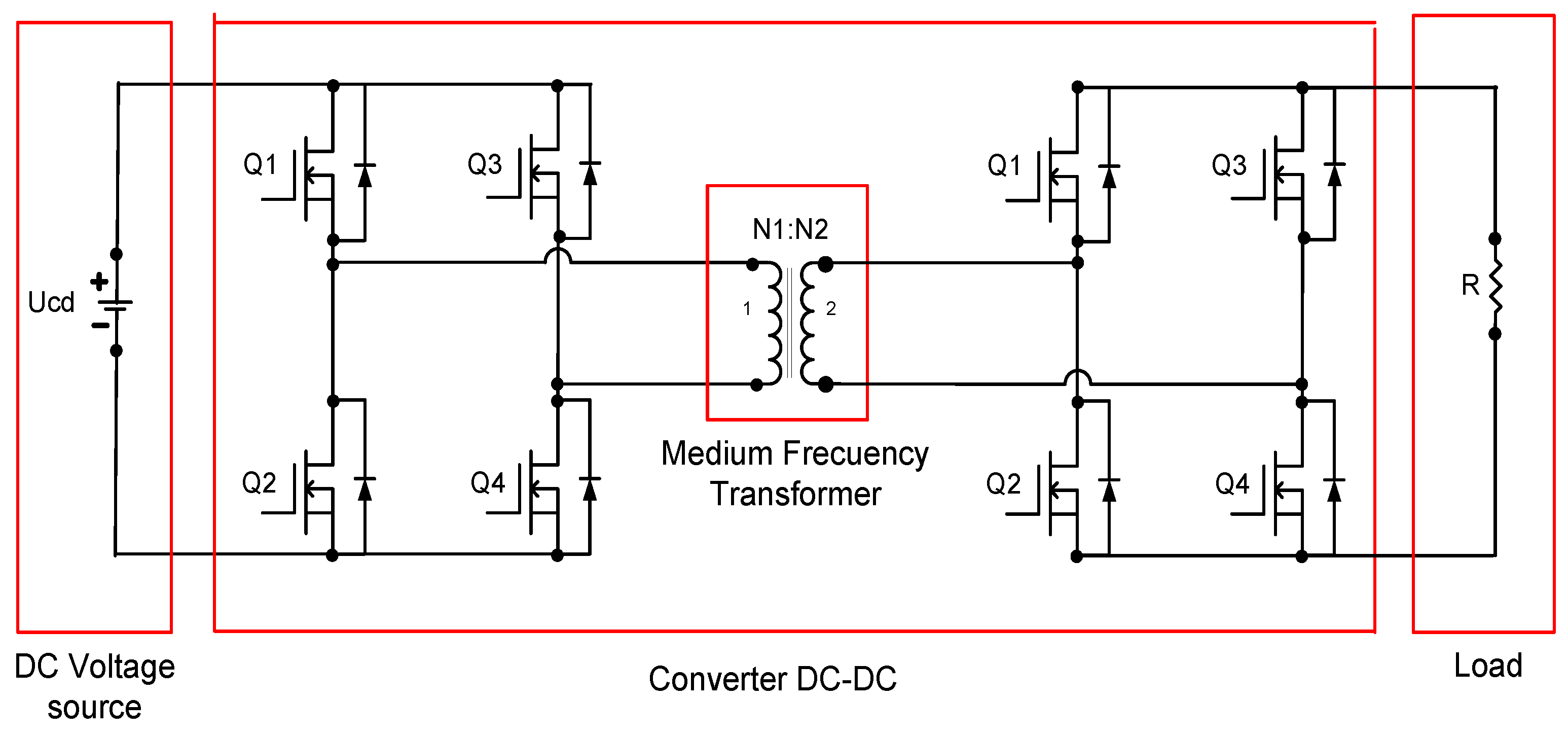
The behaviours of the three MFTs are simulated at the same input power, frequency (using sinusoidal signal) and load conditions. In addition, with the purpose of analysing the behaviour of the MFT under square signals, the transformer is connected to a DAB.
Figure 6 shows the MFT testing system for sinusoidal waveforms, and
Figure 7 shows the testing system for square waveforms.
Table 6 shows the parameters of the three MFTs used in simulations. Notice that MFT2 has the highest dispersion inductance,
Ld1. Therefore, it has the highest output power control range. It should be mentioned that a lower
Ld1 lowers ψ.
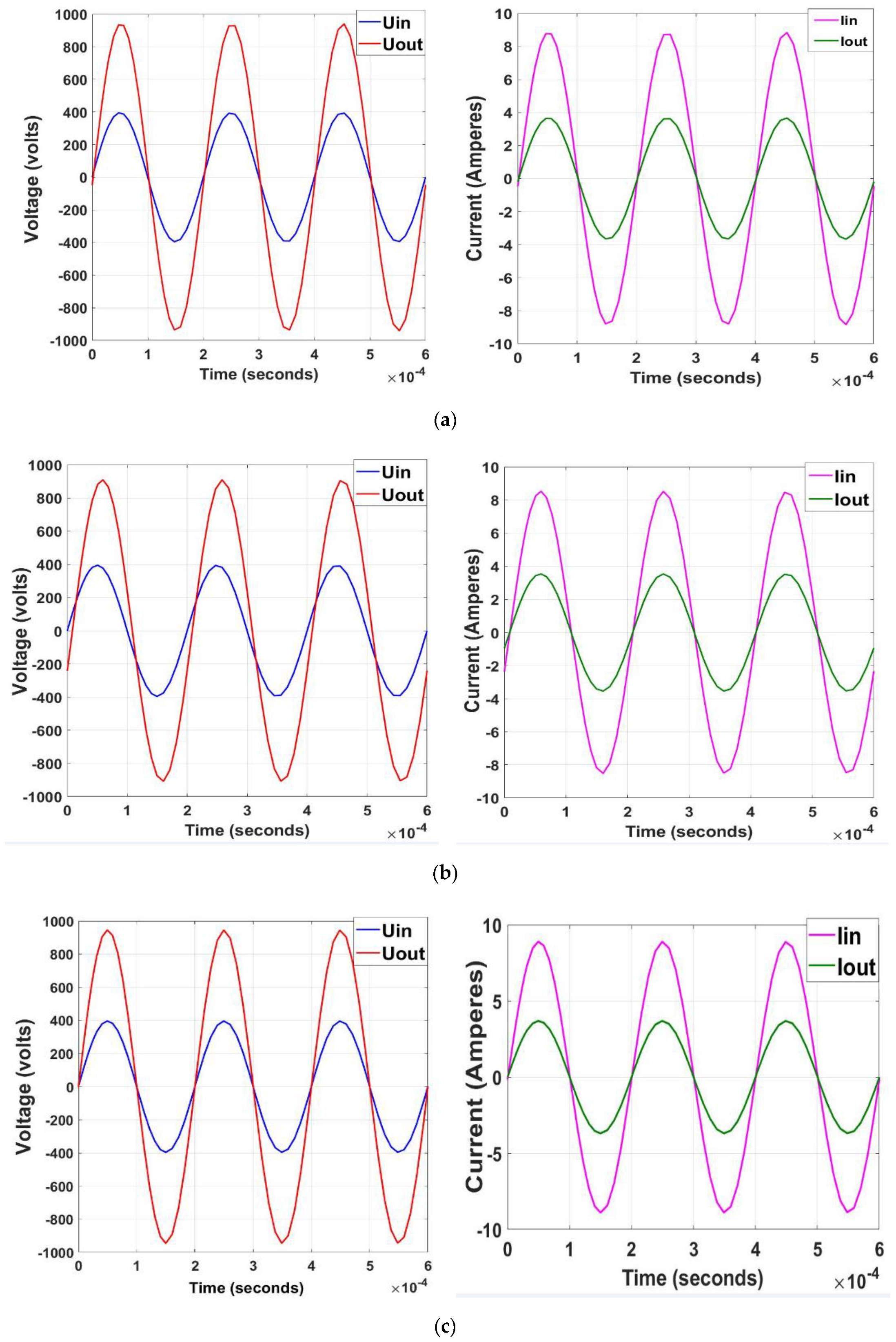
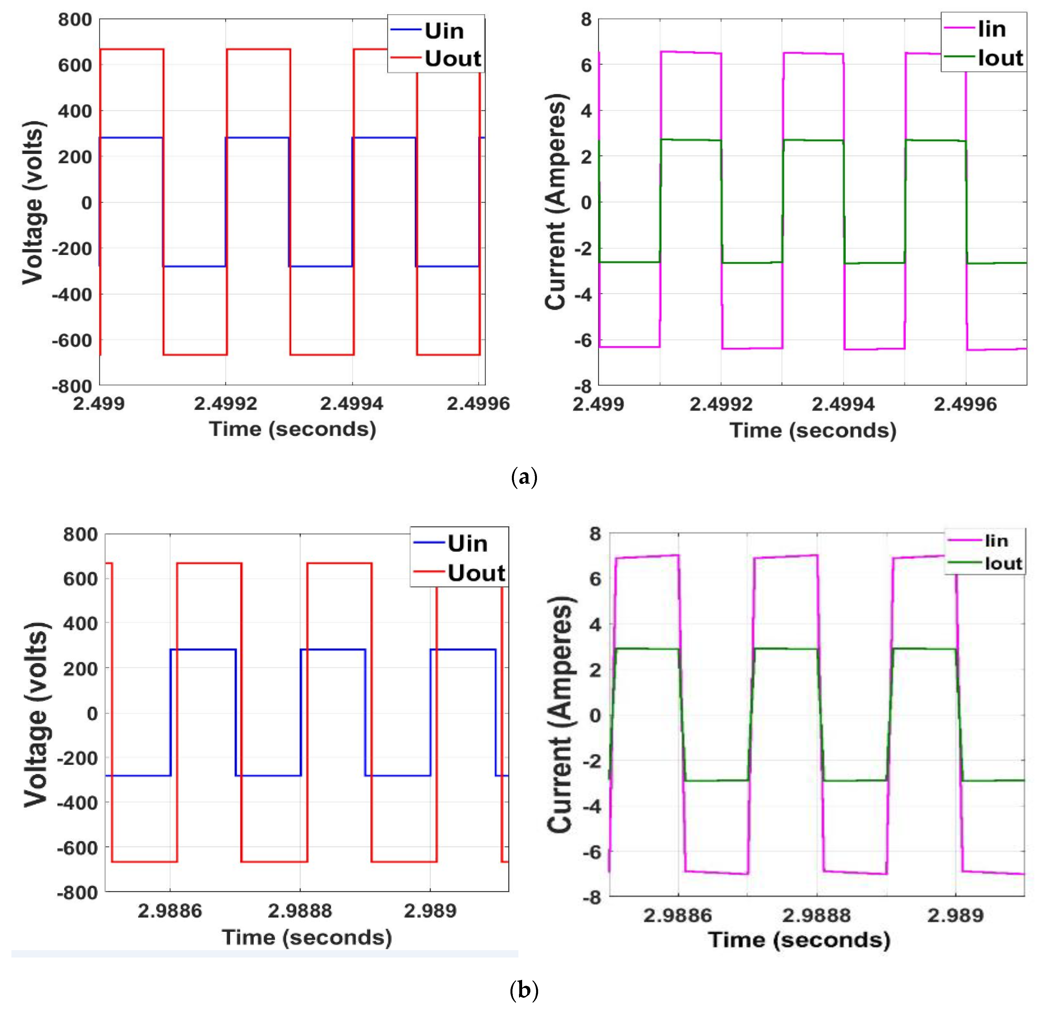
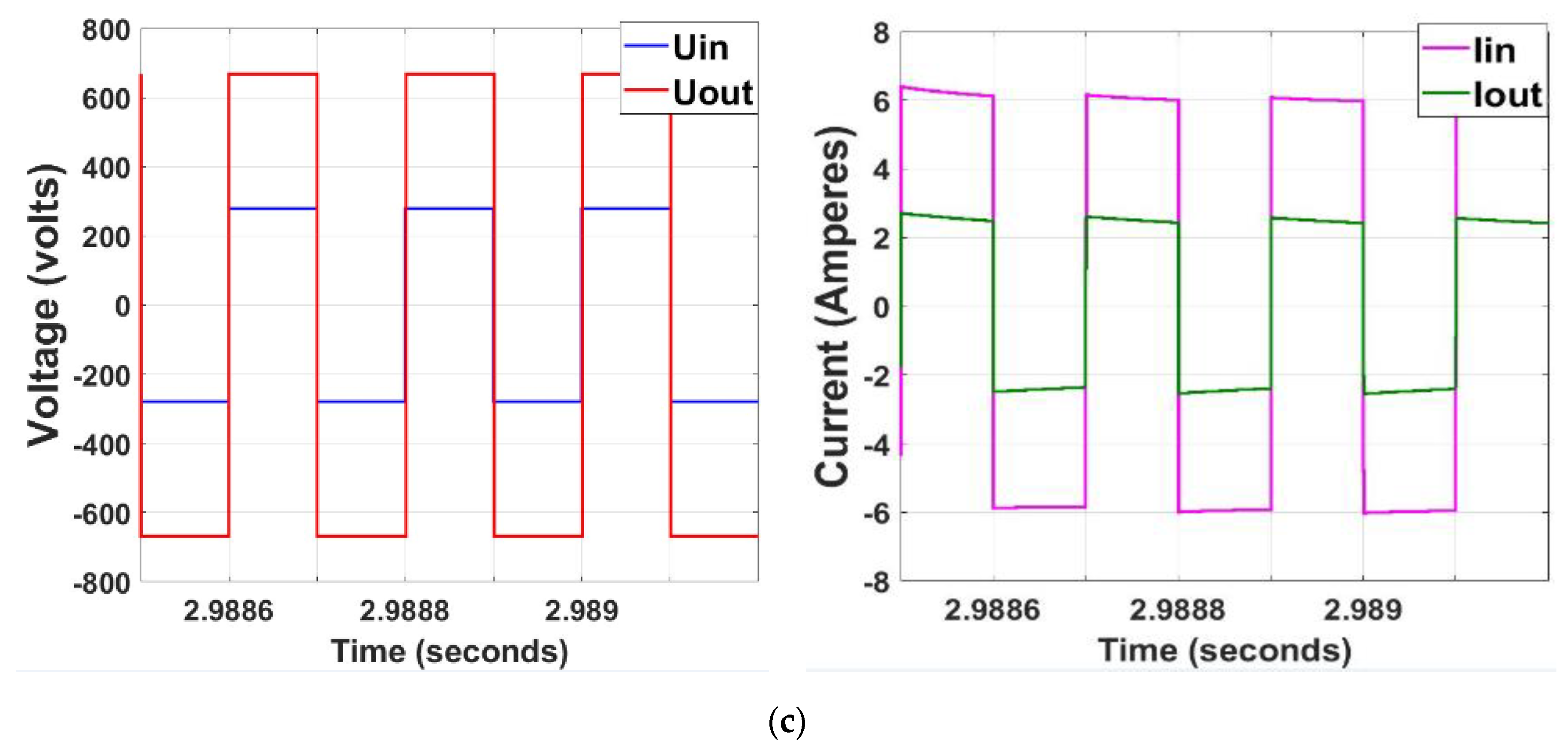
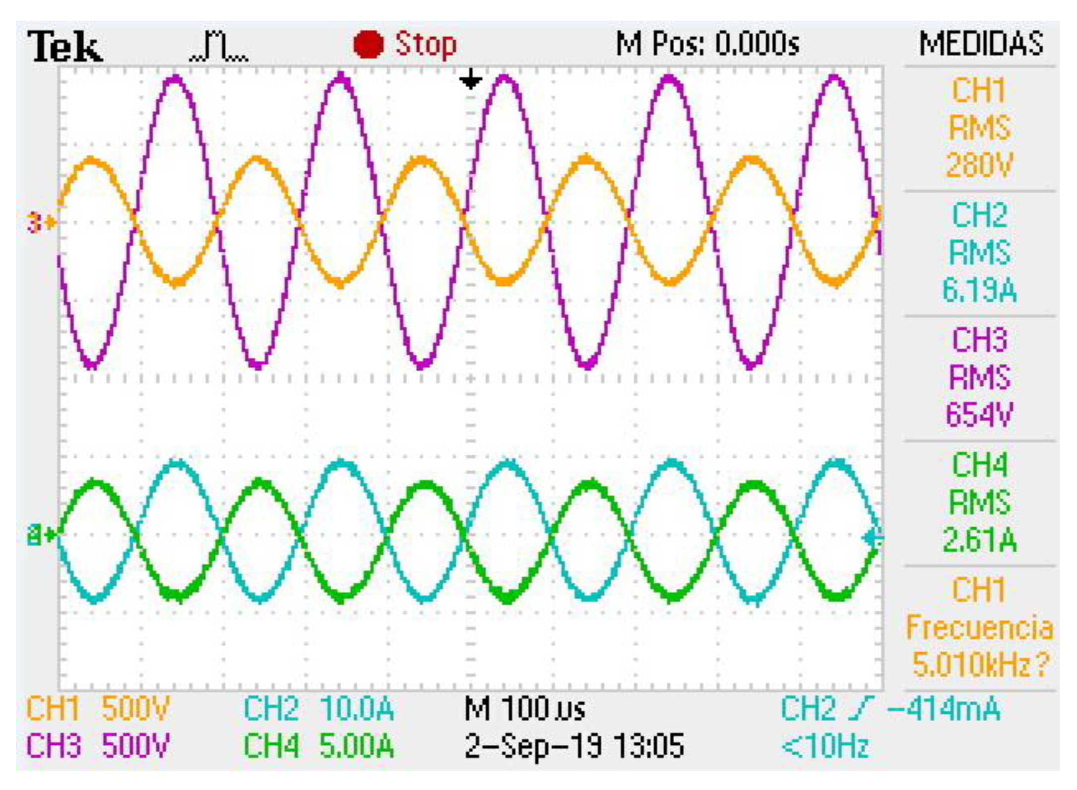
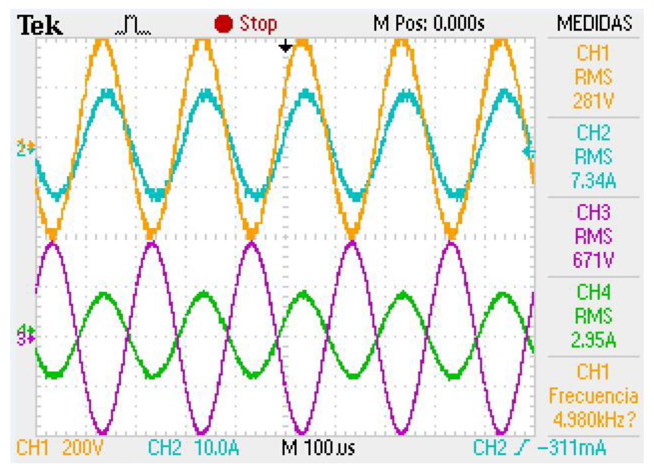
Figure 8 and
Figure 9 show the input and output voltages and currents of the three MFTs fed with sinusoidal and square signals, respectively.
Table 7 and
Table 8 present the voltage and current values, as well as the efficiency of each MFT fed with sinusoidal and square signals, respectively.
As shown in
Table 7, MFT1 has 2.41% and 0.79% higher efficiency than MFT2 and MFT3, respectively.
According to
Table 8, the MFT1 has 0.18% higher efficiency with square waveforms than with sinusoidal, while the MFT2 is more efficient at 1.61% and the MFT3 is 0.11%. In
Section 5, these results are validated using MFT prototypes. On the other hand, these results corroborate what is presented in [
25], where it was found that MFTs tend towards lower losses in the core with square waves than with sine waves. For this reason, and because of the availability of laboratory equipment,
Section 5 corroborates these results using MFT prototypes with a sine wave and knowing that, with square waves, greater efficiencies would be obtained [
25].
7. Discussion
Table 10 presents the most recent research on MFTs with toroidal core, CC core and shell core operating at a medium frequency range.
Each proposal in
Table 10 includes an experimental prototype. In [
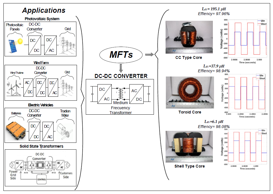
20] and [
22], an MFT with the toroidal core is presented, tested at 5 and 1 kHz, respectively. Both MFTs have an efficiency above 99%, at 1 kVA but the difference between them is the power density, which was 83.3% higher in the MFT at 5 kHz. This difference is because the higher the frequency, the higher the power density.
In [
21] and [
3], CC cores are used. Although this type of core has a very thin air gap, there is an increase in dispersed flow and, finally, an increase in losses, thus reducing efficiency. The difference between this core and the toroidal is presented in
Section 6.
Using other type of core, in [
4] and [
2] shell cores are used, at 5 and 20 kHz with powers at 50 and 10 kVA, respectively. The MFT in this case has an efficiency of 97% at 1.75 kVA and 5 kHz. On the other hand, the dispersion inductance is lower than in other MFTs. This is due to the core structure, which concentrates most of the magnetic flux in the transformer core.
The magnitude of the dispersion inductance is key to defining the power output control of DC-DC converters with DAB. This is because these converters require a minimum dispersion inductance to establish the amplitude of the control range of the output power [
4].
The analysis and results presented in this research work provide useful information for the selection of the most suitable core geometry to meet the requirements of high efficiency or a higher output power control range, for example. A design objective is to obtain a high value for the dispersion inductance in the MFT in order to use inductances external to the MFT. If the MFT alone has, or surpasses, the minimum dispersion inductance, then the external inductances might not be necessary. In this case, a wide-range output power control of the DC-DC converter can be achieved.

 ,
, 


