Article

Modeling and Stability Analysis of Parallel Inverters in Island Microgrid

Key Lab of Power Electronics for Energy Conservation and Motor Drive of Hebei Province, College of Electrical Engineering, Yanshan University, Qinhuangdao 066004, China
*
Author to whom correspondence should be addressed.
Electronics 2020, 9(3), 463; https://doi.org/10.3390/electronics9030463
Submission received: 10 February 2020 / Revised: 3 March 2020 / Accepted: 7 March 2020 / Published: 10 March 2020

Abstract

:
The island microgrid is composed of a large number of inverters and various types of power equipment, and the interaction between inverters with different control methods may cause system instability, which will cause the power equipment to malfunction. Therefore, effective methods for analyzing the stability of the microgrid system have become particularly important. Generally, impedance modeling methods are used to analyze the stability of power electronic converter systems. In this paper, the impedance models of a PQ-controlled inverter and droop-controlled inverter are established in d-q frame. In view of the difference of output characteristics between the two control methods, the island microgrid is equivalent to a double closed-loop system. The impedance model of the parallel system is derived and the open loop transfer function of the system is extracted. Based on the generalized Nyquist criterion (GNC), the stability of parallel system working in island microgrid mode is analyzed using this proposed impedance model. The simulation and experiment results are presented to verify the analysis.

1. Introduction

At present, with the development of new energy sources such as photovoltaics and wind power, the microgrid has attracted extensive attention from the society and academia [1]. The microgrid is a single-control independent power generation system composed of distributed generations (DG), loads, energy storage devices, and control devices. It can operate in grid-connected mode and island mode [2]. Nowadays, the stability of power electronic networks has received widespread attention [3], and the stability of island microgrid systems has gradually become the focus of research [4].
In island microgrid system, inverters with different control modes exist in each DG unit. These inverters are connected to common AC bus through distribution cable. Distribution cable impedance exists due to the problem of interconnection line distance. The interaction between distribution cable impedance and different control modes of inverters will cause resonance and affect system stability [5]. Therefore, how to analyze the system stability of the island microgrid through theoretical research and the accurate design of the system has become an important research direction.
There are many kinds of power electronic devices in microgrid, which are easily affected by disturbance, so it is necessary to analyze the stability of small signal in microgrid. Small signal stability refers to the ability that the power system in synchronization state has to return to synchronous operation without spontaneous oscillation or non-periodic out of step after small interference [6]. There are many analysis methods using small signal modeling, while the traditional method for power system stability analysis is the state space method, which can analyze the definite meaning of stability. When analyzing the stability of the state space model, the certainty of the system is needed. However, for a flexible and variable microgrid system, its capacity is small and scattered, and the structure of the constituent units is easy to change, the parameters need to be recalculated, and portability is poor [7]. In addition, the state space matrix constructed by the inverter system has a higher order, and the order of the parallel inverter will increase exponentially. The final model is more and more complicated and difficult to implement [8]. Because the three-phase stationary coordinate system can be transformed into the two-phase stationary coordinate system α-β frame and the two-phase rotating coordinate system d-q frame through the Clark transformation and Park transformation, the model has a new representation method. Therefore, scholars have proposed an impedance-based modeling method [9] which takes the input and output of the inverters as impedance models, greatly simplifying the difficulty of modeling.
Impedance modeling methods are divided into harmonic linearization modeling [10,11] and d-q frame modeling [12]. In harmonic linearization modeling, complex phase sequence transformation and algebraic operations are required according to the circuit structure, which increases the difficulty of modeling and lacks of research on parallel systems. And the small-signal impedance model of the three-phase inverter established by this method still has coupling impedance components between positive and negative sequences [13,14,15]. In [16], a partial impedance model is established in the α-β frame. The impedance model can be analyzed in the unified coordinate system, but the overall inverter model with a power loop cannot be established in the α-β frame. In [17], the three-phase voltage-source inverter is equivalent to two coupled DC systems by using d-q frame modeling method, and the d-q frame impedance model of inverter is derived by linearization method. However, this impedance model is generally a two-dimensional matrix model, whereby the traditional Nyquist criterion is not applicable, so the generalized Nyquist criterion (GNC) [13,18,19] is used to measure impedances in either d-q or sequence frame to analyze the impedance stability. The d-q frame impedance matrices of an active front end (AFE), a voltage-source inverter (VSI), and the grid-tied inverters (GTI) are discussed in [20], which verified the applicability and effectiveness of GNC. The stability of the system from the perspective of the influence between the parallel inverter and the distribution cable impedance is discussed in [21]. The source-load system of three-phase inverter can be presented as Norton and Thevenin equivalents to establish the impedance model of the parallel inverter system [22]. The method of establishing the impedance model of the parallel converter system and how to analyze the stability of the impedance model are given in [23]. The circuit analysis methods of the inverter circuit are given in [24,25], which provides the basis for modeling in this paper. According to the above, the existing models shown above mainly study the parallel connection of inverters in the α-β frame or the same control method. This article will complement this research deficiency and establish inverter parallel models of different control methods in the d-q frame. In addition, the influence of the distribution cable impedance is also considered. This model can not only study the influence of parameter changes of a single inverter, but also analyze the parallel stability of multiple units, which has certain novelty.
The rest of this paper is organized as follows. In Section 2, the common output impedance models of PQ-controlled inverter and droop-controlled inverter are established firstly. In Section 3, the whole model of island microgrid system is built and the open loop transfer function of the system is extracted. In Section 4, the stability of the system under different conditions is analyzed by GNC, and the correctness of the previous theoretical analysis is verified by simulation. In Section 5, the correctness of the analysis results is verified by experiments, which proves the accuracy and effectiveness of the model. Finally, the paper summarizes and points out the problems that should be paid attention to in system design in Section 6.

2. Output Impedance Model of Inverter

2.1. Open-Loop Output Impedance Model

Figure 1 is the schematic diagram of the main circuit of the three-phase inverter with a LC filter. According to the circuit principle, the small signal mathematical model [24,25] of the inverters in d-q frame can be obtained as shown in Equation (1).
{ [ R L + s L ω L ω L R L + s L ] [ i L d i L q ] = [ u i d u i q ] [ u o d u o q ] [ 1 + s R c C ω R c C ω R c C 1 + s R c C ] 1 [ s C ω C ω C s C ] [ u o d u o q ] = [ i L d i L q ] [ i o d i o q ]
According to Equation (1), the open-loop transfer function block diagram of the inverter in d-q frame can be obtained in Figure 2.
The small-signal variable relationship of the open-loop for inverter is set as Equation (2).
i o d q = I G L L u i d q + G L L I + G L L G C C u o d q
where
G L L = [ R L + s L ω L ω L R L + s L ] ,   G C C = [ 1 + s R c C ω R c C ω R c C 1 + s R c C ] 1 [ s C ω C ω C s C ] ,   I = [ 1 0 0 1 ]

2.2. Impedance Model of PQ-Controlled Inverter

Figure 3 is the control block diagram of the PQ-controlled inverter.
According to Figure 3, the expression between the duty ratio and the output current can be acquired in Equation (3).
[ d d d q ] = [ K p + k i / s 0 0 K p + k i / s ] ( [ i o d i o q ] [ i o d i o q ] )
From Equations (2) and (3), the unfiltered output voltage of the inverter can be obtained through small signal processing in Equation (4).
u d q = G P W M G p i ( i o d q i o d q )
where
G P W M = [ G p w m 0 0 G p w m ] ,   G p i = [ K p + k i / s 0 0 K p + k i / s ]
Through the above analysis, the overall current source controlled inverter system can be divided into two parts: the main circuit and the control circuit. When the influence of the power loop is ignored, the output reference value of the power loop is constant. The equivalent model of PQ-controlled inverter is shown in Figure 4. The relationship between output current and output voltage and input current reference value can be derived in Equations (5) and (6), the final expression of io under PQ-controlled inverter can be acquired as Equation (7) by Equations (5) and (6).
i o d q | u o d q = 0 = G P W M G p i G L L + G P W M G p i i o d q
i o d q | i o d q = 0 = 1 + G L L G C C G L L + G P W M G p i u o d q
i o d q = K i i o d q Y i u o d q
where
K i = G P W M G p i G L L + G P W M G p i ,   Y i = 1 + G L L G C C G L L + G P W M G p i
The PQ-controlled inverter is equivalent to the current source, and the Norton equivalent circuit is constructed. The Norton equivalent circuit of the PQ-controlled inverter is constructed in Figure 5a. Considering the influence of distribution cable impedance, when Zline is not zero, the Norton equivalent circuit is constructed in Figure 5b.
Equation (8) can be obtained from Figure 5. The existence of distribution cable impedance will affect the gain of closed-loop transfer function of PQ-controlled inverter and the equivalent output impedance at PCC, which indicates that distribution cable impedance will have a certain impact on the stability of PQ-controlled inverter.
i o = 1 1 + Y i Z l i n e ( K i i o Y i u p c c )
where
Z l i n e = R l i n e + s L l i n e

2.3. Impedance Model of Droop-Controlled Inverter

Figure 6 is the block diagram of the droop-controlled inverter, which also ignores the influence of the power loop, i.e., the constant output reference value of power loop. The control model of the voltage and current loop is derived according to Figure 6. The expressions for obtaining the reference value of the inductor current in the d-q frame system are listed in Equation (9).
i L d q = G v u o d q G v i o d q
where
G u = [ K p u + k i u / s 0 0 K p u + k i u / s ]
Then construct an expression for the duty ratio in Equation (10).
d d q = G i ( i L d q i L d q )
where
G i = [ K p i + k i i / s 0 0 K p i + k i i / s ]
The droop control inverter takes the output voltage as the control amount, and can express the relationship between the small signal variables as follows in Equation (11).
{ i L = G i i i o + G i d d u o = G u i i o + G u d d
The relationship between the inductor current and the output current in the three-phase stationary coordinate system can be obtained in Equation (12).
i L i o = s L + R L + 1 s C + R C 1 s C + R C
The relationship between the inductor current and the output current in d-q frame can be obtained in Equation (13):
[ i L d i L q ] = G i i [ i o d i o q ]
where
G i i = I I + G C C G L L
In a similar way, the small-signal relationship between duty cycle and inductor current can be obtained in Equation (14).
i L d = G p w m s L + R L + 1 s C + R C
The transfer relationship between the duty ratio and the inductor current can be obtained in Equation (15).
G i d = G P W M G C C I + G C C G L L
The relationship between output current and output voltage can be obtained in Equation (16) and the corresponding relationship between output voltage and duty cycle can be obtained in Equation (17).
G u i = G L L I + G L L G C C
G u d = G P W M I + G C C G L L
The closed-loop control block diagram after the power loop is ignored can be obtained as shown in Figure 7.
According to Figure 7, the relation of output current and reference voltage with output voltage can be obtained as Equations (18) and (19).
u o d q | i o d q = 0 = G u G i G u d I + G i d G i G u G i G u d u o d q
u o d q | u o d q = 0 = A B i o d q
where
A = G u d G i G i i I + G i G i d G u i ,   B = I + G u d G u G i I + G i G i d
Equation (20) can be obtained by Equations (18) and (19).
u o d q = K u u o d q Z o i o d q
where
K u = G u G i G u d I + G i d G i G u G i G u d ,   Z o = A B
When the distribution cable impedance Zline is considered, the bus voltage can be expressed as Equation (21) and the corresponding Thevenin equivalent circuit is obtained in Figure 8.
u p c c d q = K u u o d q Z o i o d q Z l i n e i o d q = K u u o d q ( Z o + Z l i n e ) i o d q
In Equation (21), the total output impedance of the droop-controlled inverters in the microgrid is affected by their own output impedance Zo and distribution cable impedance Zline, while the output impedance Zo of the inverter is mainly affected by the parameters of the controller, which has a greater impact on the stability of the system.

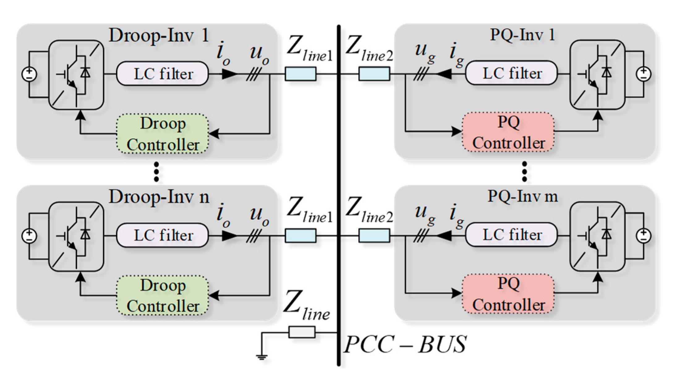
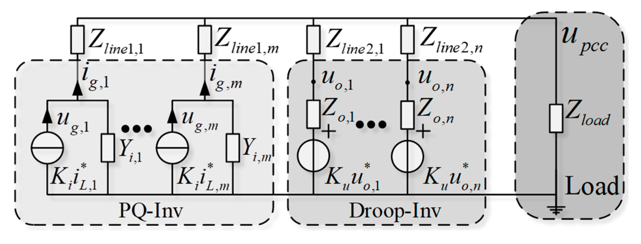
3. Parallel Inverter Model under the Island Condition

3.1. Establishment of Parallel Inverter Model

In this paper, the control mode of the inverter in the island microgrid mainly adopts droop control and PQ control. Different control units are connected to the same bus. The simplified island microgrid is shown in Figure 9.
According to the difference of output characteristics between droop-controlled inverter and PQ-controlled inverter, the equivalent model of Figure 9 is obtained in Figure 10, where Zline1,m are the distribution cable impedance of the m-th PQ-controlled inverter and Zline2,n are the distribution cable impedance of the n-th droop-controlled inverter. The local load of the microgrid is Zload.
Let Yline1,k = 1/Zline1,k, Yline2,s = 1/Zline2,s, Zi,m = 1/Yi,m, Yo,s = 1/Zo,s, Yload = 1/Zload, assuming that the parameters of the inverter of the same control mode are the same in the system, which is Yo,s = Yo = 1/Zo, Zi,s = Zi = 1/Yi (k = 1, 2, …, m; s = 1, 2, …, n). According to Figure 9, the nodal voltage equation [23,26] of the system can be obtained as Equation (22):
( Y l o a d + m Y i Y l i n e 1 Y i + Y l i n e 1 + n Y i Y l i n e 2 Y o + Y l i n e 2 ) u p c c = Y l i n e 1 Y i + Y l i n e 1 s = 1 m K i i L , s + Y o Y l i n e 2 Y o + Y l i n e 2 r = 1 n K u u o , r
It is considered that the local load is passive load and written as impedance expression, then Equation (22) can be further written as Equation (23).
u p c c = 1 n 1 1 + L ( s ) ( K u r = 1 n u o , r ( Z o + Z l i n e 2 ) i L o a d + 1 1 + Z l i n e 1 Z ( Z o + Z l i n e 2 ) K i s = 1 m i L , s )
where
L ( s ) = [ L d d ( s ) L d q ( s ) L q d ( s ) L q q ( s ) ] = m ( Z o + Z l i n e 2 ) n ( Z i + Z l i n e 1 )
If the difference of inverter output characteristics under different control modes is ignored, it is unified as Norton equivalent impedance model in Figure 11.
In Figure 11, the microgrid equivalent model under the unified model is only a single closed-loop system, which cannot fully reflect the different output characteristics of the parallel system of the droop-controlled inverters and PQ-controlled inverters. Therefore, the island microgrid can be equivalent to a double closed-loop system by Equation (23). As shown in Figure 12, the reference current of PQ inverter and the reference voltage of droop inverter can be regarded as input, the load current as disturbance, and the voltage of PCC as output.

3.2. Stability Criterion Based on Impedance Model of Island Microgrid

The equivalent control block diagram of island microgrid shows that the model of double closed-loop system is more accurate, and according to Equation (23), the open-loop transfer function of double closed-loop system is L(s), i.e., Equation (24). Since L(s) is a second-order matrix form, the traditional Nyquist criterion is not applicable, so the more efficient GNC is adopted. L(s) reflects the matching characteristics of the integrated output impedance of the droop-controlled inverter and the integrated output impedance of the PQ-controlled inverter. Therefore, the stability of the parallel inverters is mainly analyzed by L(s) and so as to optimize the design of output impedance of the single inverter to weaken the interaction between inverters in the microgrid and suppress the resonance.

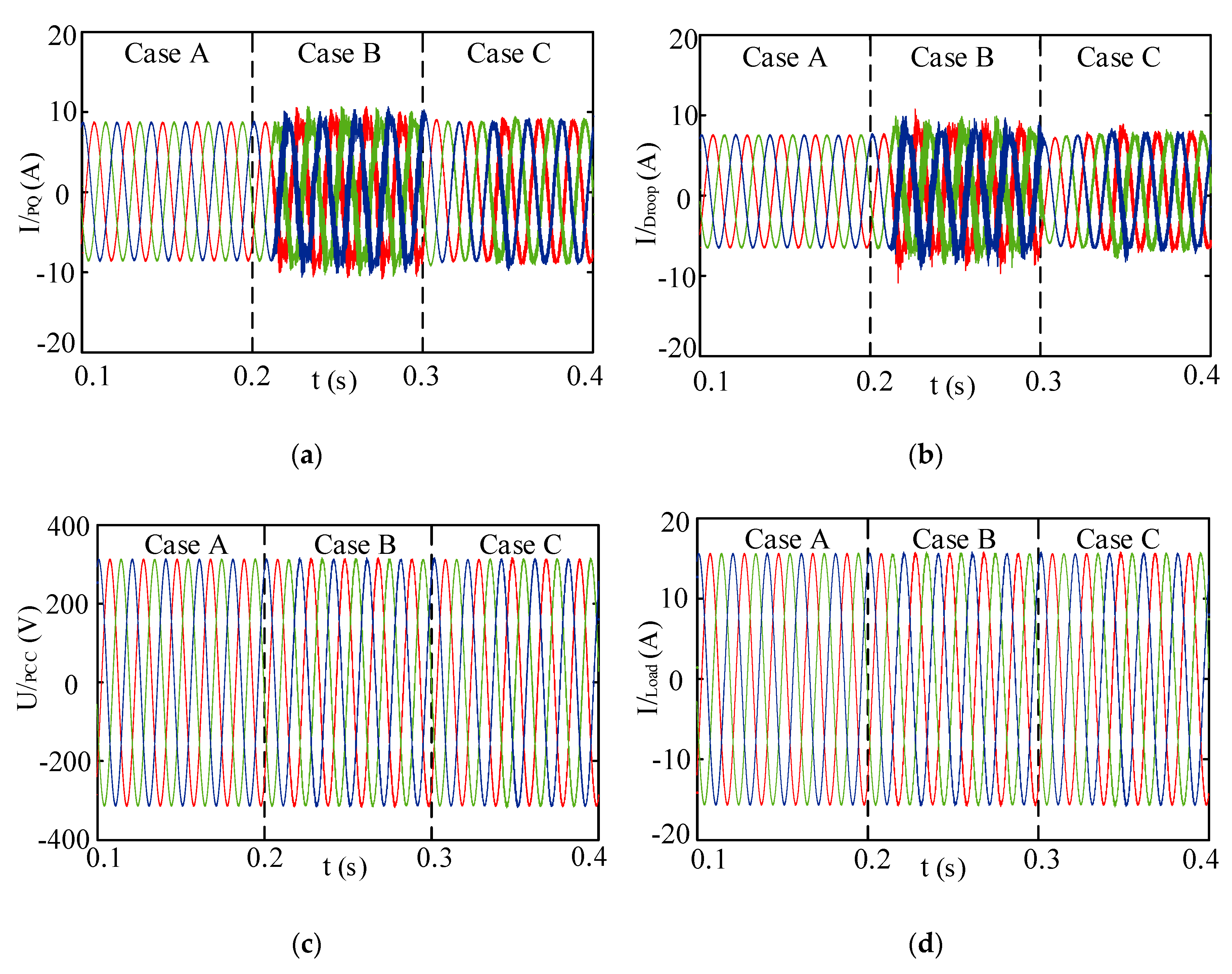
4. Stability Analysis and System Simulation

The inverters under the parameters given in this section are all stable in the stand-alone operation, so neither Zo + Zline2 nor Zi + Zline1 in L(s) have right half-plane poles, so the stability of the system is stable if and only if the net sum of anticlockwise encirclement of the critical point (−1,0) by the characteristic loci of the return ratio L(s) is equal to zero according to the GNC. Finally, the correctness of the stability analysis is verified in Matlab simulation. The control and circuit parameters are listed in Table 1.

4.1. Effect of Current Loop PI on the Stability of Parallel System

The current-loop PI parameters can be obtained by calculating the inner-loop bandwidth of the system through the amplitude-frequency characteristics and the switching frequency [27]. In order to verify the correctness of the model, the current-loop PI values will be changed for verification. Firstly, there is a PQ-controlled inverter and a droop-controlled inverter in the island microgrid. The distribution cable impedance is fixed at resistance 0.1 Ω and inductance 0.3 mH. When other parameters remain unchanged, the current loop PI of the two inverters is changed from Case A (Kp = 0.5, Kii = 80; Kpi = 0.8, Kii = 120) to Case B (Kp = 0.05, Kii = 20, Kpi = 0.08, Kii = 30), and finally to Case C (Kp = 0.005, Kii = 5, Kpi = 0.008, Kii = 6).
Figure 13 is the characteristic loci of L(s) with different current loop PI. In Case A, (−1,0) point is not encircled by the characteristic loci, and the system is stable. In Case B, (−1,0) point is not still encircled, but the intersection point with the real axis is close to (−1,0) point. In Case C, (−1,0) point is encircled once, indicating that the system is in an unstable state. The following is validated by simulation.
Firstly, the parallel system is operated under the condition of Case A. When t = 0.1 s, the droop-controlled inverter and the PQ-controlled inverter run in parallel to the steady state. When t = 0.2 s and t = 0.3 s, PI parameters change to Case B and Case C respectively. The simulation results are shown in Figure 14.
In Figure 14, PCC voltage and output current are in a stable state in Case A. The PQ-controlled output current has a small amount of resonance, and the system is still in a stable state in Case B. In Case C, serious resonance phenomena occur in each output, and the system is in an unstable state. The simulation results are the same as the theoretical analysis.

4.2. Influence of Distribution Cable Impedance on System Stability

The influence of distribution cable impedance on the stability of the parallel inverters is studied. Similarly, a PQ-controlled inverter and a droop-controlled inverter are set in the microgrid. The resistance of two distribution cables is fixed at 0.1 Ω. When other parameters are unchanged, the distribution cable inductance is changed in turn, which changes from Case A (Lline_droop = 0.8 mH; Lline_PQ = 0.3 mH) to Case B (Lline_droop = 0.3 mH; Lline_PQ = 0.8 mH) and finally to Case C (Lline_droop = 0.8 mH; Lline_PQ = 0.8 mH).
In Figure 15 is the characteristic loci of L(s) with different distribution cable inductance, the distribution cable impedance of PQ-controlled inverter does not change, and the impedance of the contact line of droop-controlled inverter increases in Case A. The characteristic loci is (−1,0) points, and the system remains stable. The influence of output impedance is small. In Case B, the distribution cable impedance of droop-controlled inverter is unchanged, and the distribution cable impedance of PQ-controlled inverter is increased. The characteristic loci is far beyond the (−1,0) point and the system is in an extremely unstable state. In Case C, the distribution cable impedance of the two inverters increases at the same time, the characteristic loci still surrounds the (−1,0) point, and the system is still in an unstable state. However, compared to Case B, the characteristic loci near the (−1,0) point, the system stability is relatively improved.
The simulation results of Figure 15 are as follows in Figure 16.
In Figure 16, the system is in a stable state in Case A. In Case C and Case B, the output current of PQ-controlled inverter and droop-controlled inverter has serious resonance, and the PCC voltage and load current are also affected to a certain extent. At this time, the system is in an unstable state, and Case B is less stable than Case C, which is the same as the theoretical analysis results above.

4.3. Effect of Different Inverter Number on System Stability

When a droop-controlled inverter runs stably on load, the number of PQ inverters m increases from 1 to 4. When a droop-controlled inverter runs stably on load, a PQ inverter is put into operation. When the parallel system reaches stability, the number of droop-controlled inverters n increases from 1 to 3, corresponding to the Nyquist diagram shown in Figure 17.
In Figure 17a, the characteristic loci of L(s) is closer to (−1,0) point with the number of PQ-controlled inverters increases. This indicates that the stability of the microgrid system is getting worse. When the number of PQ-controlled inverters reaches four, the system is in an unstable state, while the increase in droop-controlled inverters has the opposite effect. When the number of droop-controlled inverters increases, the system is closer to stability. The simulation results of different PQ-controlled inverters number are as follows.
In Figure 18, when the 4th PQ-controlled inverter is added into the system, which causes the resonance of PCC voltage and other output currents in the figure, the system becomes extremely unstable, which is the same as the theoretical analysis results above.

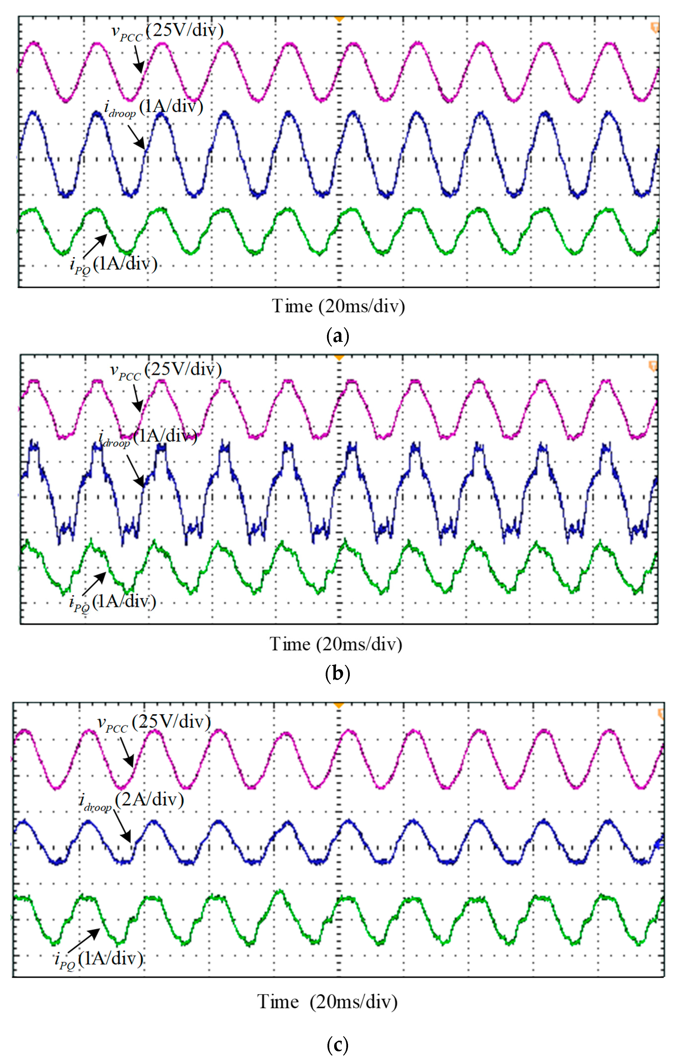
5. Experiment Results

In order to verify the above theory, two three-phase inverters experiment platform is built. The main control chips of the experimental control circuit are composed of DSP (Digital Signal Processor, Texas Instruments, Dallas TX, USA) of TMS320F28335 model and FPGA (Field Programmable Gate Array, Altera, CA, USA) of EP3C25Q240C8N model.
Figure 19 shows a-phase output waveform of a droop-controlled inverter and a PQ-controlled inverter running stably in parallel. Experiments on reducing the PI parameters of the current loop and increasing the distribution cable impedance are carried out under the same other operating conditions. vPCC represents the PCC voltage, vdroop and idroop represents output voltage and output current of the droop-controlled inverter, moreover vPQ and iPQ represents output voltage and output current of the PQ-controlled inverter, all of them are respectively shown in all the following experimental diagrams.
A-phase output waveforms of the two inverters operating in parallel after reducing the PI parameters of the current loop are shown in Figure 20.
As Figure 20 shows, after the current loop PI parameters of two parallel inverters are reduced, the PCC point voltage and the output current of each inverter are disordered, and the amplitude and frequency of the waveform are not in line with the experimental requirements. After a short time change in this disordered state, an excessive current pulse is generated, which triggers the automatic protection function of the droop-controlled inverter, the drive is disconnected, and the system operation is in a disordered state. Similar to the corresponding simulation in Figure 14, this disorder also occurs in the simulation, but the simulation is an ideal condition and no overcurrent protection occurs. This situation is a system instability in both simulation and experiment, and this is consistent with the results of the GNC analysis of Figure 13.
Figure 21 show the A-phase output waveform of the two inverters operating in parallel after changing the distribution cable impedance, from Case A (Lline_droop = 1.2 mH; Lline_PQ = 0.5 mH) to Case B (Lline_droop = 0.5 mH; Lline_PQ = 1.2 mH), and finally to Case C (Lline_droop = 1.2 mH; Lline_PQ = 1.2 mH).
As Figure 21a shows, under the condition that the distribution cable impedance of the PQ-controlled inverter is constant, after increasing the distribution cable impedance of the droop-controlled inverter, the PCC voltage and the output current waveform quality of each inverter is good, indicating that the system can still run stably. From Figure 21b, it can be seen that, after increasing the distribution cable impedance of the PQ-controlled inverter, the output current of each inverter has a severe resonance phenomenon, which affects the PCC voltage to generate obvious harmonics. The waveform quality is very poor at this time, does not meet the power quality requirements, so the system is in an unstable state. In Figure 21c, after increasing the contact line impedance of the two inverters at the same time, the output current of each inverter contains obvious harmonics, the waveform quality is poor. However, after increasing the distribution cable impedance of the droop-controlled inverter, the PCC voltage and the output current waveforms are significantly improved compared to the situation in Figure 21b. Comparing the experimental Figure 21 with the simulation Figure 16, it can be found that, in the same three cases, after increasing the distribution cable impedance of the droop-controlled inverter, the output waveforms of the system are all stable, and have a certain effect on improving the stability of the system. However, the increase of the distribution cable impedance of PQ-controlled inverter will result in a large number of harmonics in the output waveform, indicating that the system is in an unstable state at this time. These results also correspond to the GNC stability analysis in Figure 15, which is consistent with the theoretical analysis.
The above experimental results and analysis verify that the built model in this article can perform accurate stability analysis through stability criteria, and further prove the reliability and correctness of the parallel inverters models with different control methods in practical applications. It provides an important basis for the theoretical analysis of future engineering practice.

6. Conclusions

In this paper, the impedance model of an island microgrid system is constructed. The control methods of inverters in the system mainly adopt droop control and PQ control. Since the influence of the distribution cable impedance cannot be ignored, the impedance model with the inverter and the distribution cable impedance is established in the d-q frame system. The transfer function of the double closed-loop in the inverter parallel system is constructed due to the output characteristics of the different control methods and the model that can reflect the impedance matching of system is extracted. The stability of the system is analyzed by the GNC and model, and the correctness of the analysis results are verified by simulation and experiments, which proves the accuracy and effectiveness of the model. This will play an important role in studying the stability of the island microgrid system. The method for the research in this paper is also applicable to the converter that can be equivalent to the controlled voltage source and the controlled current source. Through such modeling and analysis, the operational state of the microgrid parallel system can be analyzed effectively and it has important significance in parameter design and optimization.
At the same time, this paper draws the following conclusions through theoretical analysis, simulation, and experiment verification:
(1)
The voltage at PCC is easier to be affected by the change of output impedance of PQ-controlled inverter in the island microgrid parallel system with PQ-controlled inverter and droop-controlled inverter. Therefore, the output impedance of droop-controlled inverter should be increased appropriately to enhance the stability of the system.
(2)
When the number of droop-controlled inverter is constant, the increase of the number of PQ-controlled inverter will easily cause resonance and reduce system stability, and when the number of PQ-controlled inverters is constant, increasing the number of droop-controlled inverters will contribute to system stability.

Author Contributions

Conceptualization, X.W. and H.Q.; Formal analysis, H.Q.; Methodology, X.W. and H.Q.; Supervision, X.W. and C.Z.; Validation, H.Q.; Writing—original draft, H.Q.; Writing—review & editing, X.W., H.Q. and P.H. All authors have read and agreed to the published version of the manuscript.

Funding

This research was funded by National Natural Science Foundation of China, grant number 51607154 and Foundation of the Higher Education Institutions of Hebei Province, grant number QN2017362.

Conflicts of Interest

The authors declare no conflict of interest.

References

  1. Ge, W.; Ma, T.; Zhu, Y.; Wang, S.; Gao, K.; Li, J. Research on Joint Planning of the Source-Grid-Load with New Energy System Energy Balance and Economy. In Proceedings of the 2018 International Conference on Engineering Simulation and Intelligent Control (ESAIC), Changsha, China, 24–25 August 2018; pp. 73–77. [Google Scholar]
  2. Baneshi, E.; Kalali, S.M.H.; Dehkordi, A.B. Microgrid Optimal Planning in Two Functional Modes Grid Connected and the Intentional Islanding. In Proceedings of the 2019 5th Conference on Knowledge Based Engineering and Innovation (KBEI), Tehran, Iran, 28 February–1 March 2019; pp. 857–863. [Google Scholar]
  3. Hasan, A.S.M.K.; Chowdhury, D.; Khan, M.Z.R. Scalable DC Microgrid Architecture with a One-Way Communication Based Control Interface. In Proceedings of the 2018 10th International Conference on Electrical and Computer Engineering (ICECE), Dhaka, Bangladesh, 20–22 December 2018; pp. 265–268. [Google Scholar]
  4. Pournazarian, B.; Karimyan, P.; Gharehpetian, G.B.; Abedi, M.; Pouresmaeil, E. Smart participation of PHEVs in controlling voltage and frequency of island microgrids. Int. J. Electr. Power Energy Syst. 2019, 110, 510–522. [Google Scholar] [CrossRef]
  5. Rocabert, J.; Luna, A.; Blaabjerg, F.; Rodriguez, P. Control of power converters in AC microgrids. IEEE Trans. Power Electron. 2012, 27, 4734–4749. [Google Scholar] [CrossRef]
  6. Xiao, Z.; Wang, C.; Wang, S. Small-signal stability analysis of microgrid containing multiple micro sources. Autom. Electr. Power Syst. 2009, 33, 81–85. [Google Scholar]
  7. Kim, D.; Moon, Y.; Nam, H. SSR small-signal stability analysis program of power systems and its application to IEEE benchmark systems. In Proceedings of the IEEE Lausanne Power Tech, Lausanne, Switzerland, 1–5 July 2007. [Google Scholar]
  8. Wang, Y.; Wang, X.; Blaabjerg, F.; Chen, Z. Harmonic instability assessment using state-space modeling and participation analysis in inverter-fed power systems. IEEE Trans. Ind. Electron. 2017, 64, 806–816. [Google Scholar] [CrossRef]
  9. Sun, J. Impedance-based stability criterion for grid-connected inverters. IEEE Trans. Power Electron. 2011, 26, 3075–3078. [Google Scholar] [CrossRef]
  10. Chen, X.; Zhang, Y.; Wang, S.; Chen, J.; Gong, C. Impedance-phased dynamic control method for grid-connected inverters in a weak grid. IEEE Trans. Power Electron. 2017, 32, 274–283. [Google Scholar] [CrossRef]
  11. Lv, J.; Cai, X. Harmonic linearization based impedance modeling of modular multilevel converters. Autom. Electr. Power Syst. 2017, 41, 136–142. [Google Scholar] [CrossRef]
  12. Wen, B.; Boroyevich, D.; Burgos, R.; Mattavelli, P.; Shen, Z. Analysis of D-Q Small-Signal Impedance of Grid-Tied Inverters. IEEE Trans. Power Electron. 2016, 31, 675–687. [Google Scholar] [CrossRef]
  13. Rygg, A.; Molinas, M.; Zhang, C.; Cai, X. A modified sequence-domain impedance definition and its equivalence to the dq-domain impedance definition for the stability analysis of ac power electronic systems. IEEE J. Emerg. Sel. Top. Power Electron. 2016, 4, 1383–1396. [Google Scholar] [CrossRef] [Green Version]
  14. Liu, W.; Xie, X.; Huang, J.; Zhang, C.; Yin, C. Frequency-coupled Impedance Model and Stability Analysis of Grid-connected Converter. Autom. Electr. Power Syst. 2019, 43, 138–146. [Google Scholar]
  15. Nian, H.; Yang, H. Impedance modeling and stability analysis of grid-connected inverters under unbalanced operation conditions. Autom. Electr. Power Syst. 2016, 40, 76–83. [Google Scholar]
  16. Wang, X.; Harnefors, L.; Blaabjerg, F. Unified Impedance Model of Grid-Connected Voltage-Source Converters. IEEE Trans. Power Electron. 2018, 33, 1775–1787. [Google Scholar] [CrossRef] [Green Version]
  17. Wen, B.; Boroyevich, D.; Burgos, R.; Mattavelli, P.; Shen, Z. Small-Signal Stability Analysis of Three-Phase AC Systems in the Presence of Constant Power Loads Based on Measured d-q Frame Impedances. IEEE Trans. Power Electron. 2015, 30, 5952–5963. [Google Scholar] [CrossRef]
  18. Belkhayat, M. Stability Criteria for Ac Power Systems with Regulated Loads. Ph.D. Thesis, Purdue University, West Lafayette, IN, USA, December 1997. [Google Scholar]
  19. Bakhshizadeh, M.K.; Wang, X.; Blaabjerg, F.; Hjerrild, J.; Kocewiak, L.; Bak, C.L.; Hesselbæk, B. Couplings in phase domain impedance modeling of grid-connected converters. IEEE Trans. Power Electron. 2016, 31, 6792–6796. [Google Scholar]
  20. Wen, B.; Burgos, R.; Boroyevich, D.; Mattavelli, P.; Shen, Z. AC Stability Analysis and dq Frame Impedance Specifications in Power-Electronics-Based Distributed Power Systems. IEEE J. Emerg. Sel. Top. Power Electron. 2017, 5, 1455–1465. [Google Scholar] [CrossRef]
  21. Zhang, X.; Chung, H.S.; Cao, L.L.; Chow, J.P.W.; Wu, W. Impedance-based stability criterion for multiple offshore inverters connected in parallel with long cables. In Proceedings of the 2017 IEEE Energy Conversion Congress and Exposition (ECCE), Cincinnati, OH, USA, 1–5 October 2017; pp. 3383–3389. [Google Scholar]
  22. Alenius, H.; Berg, M.; Luhtala, R.; Roinila, T.; Messo, T. Impedance-Based Stability Analysis of Multi-Parallel Inverters Applying Total Source Admittance. In Proceedings of the 2019 20th Workshop on Control and Modeling for Power Electronics (COMPEL), Toronto, ON, Canada, 16–19 June 2019; pp. 1–8. [Google Scholar]
  23. Wang, X.; Blaabjerg, F.; Loh, P.C. An impedance-based stability analysis method for paralleled voltage source converters. In Proceedings of the 2014 International Power Electronics Conference (IPEC-Hiroshima 2014—ECCE ASIA), Hiroshima, Japan, 18–21 May 2014; pp. 1529–1535. [Google Scholar]
  24. Wen, B.; Dong, D.; Boroyevich, D.; Burgos, R.; Mattavelli, P.; Shen, Z. Impedance-Based Analysis of Grid-Synchronization Stability for Three-Phase Paralleled Converters. IEEE Trans. Power Electron. 2016, 31, 26–38. [Google Scholar] [CrossRef]
  25. Wen, B.; Boroyevich, D.; Burgos, R.; Mattavelli, P. Modeling the output impedance of three-phase uninterruptible power supply in D-Q frame. In Proceedings of the 2014 IEEE Energy Conversion Congress and Exposition (ECCE), Pittsburgh, PA, USA, 14–18 September 2014; pp. 163–169. [Google Scholar]
  26. Corradini, L.; Mattavelli, P.; Corradin, M.; Polo, F. Analysis of parallel operation of uninterruptible power supplies loaded through long wiring cables. IEEE Trans. Power Electron. 2010, 25, 1046–1054. [Google Scholar] [CrossRef]
  27. Han, Y.; Li, Z.; Yang, P.; Wang, C.; Xu, L.; Guerrero, J.M. Analysis and design of improved weighted average current control strategy for LCL-type grid-connected inverter. IEEE Trans. Energy Convers. 2017, 32, 941–952. [Google Scholar] [CrossRef] [Green Version]
Figure 1. Three-phase inverter topology.
Electronics 09 00463 g001
Figure 2. Block diagram of open-loop transfer function for inverter.
Electronics 09 00463 g002
Figure 3. Block diagram of the PQ-controlled inverter.
Electronics 09 00463 g003
Figure 4. Equivalent model of PQ-controlled inverter.
Electronics 09 00463 g004
Figure 5. Norton equivalent circuit of PQ-controlled inverter. (a) No distribution cable impedance. (b) Including distribution cable impedance.
Electronics 09 00463 g005
Figure 6. Block diagram of the droop-controlled inverter.
Electronics 09 00463 g006
Figure 7. Equivalent model of droop-controlled inverter.
Electronics 09 00463 g007
Figure 8. Thevenin equivalent circuit of droop-controlled inverter.
Electronics 09 00463 g008
Figure 9. Module of islanded microgrid.
Electronics 09 00463 g009
Figure 10. Equivalent impedance model of islanded microgrid.
Electronics 09 00463 g010
Figure 11. Microgrid equivalent model under unified model. (a) Impedance model. (b) Block diagram.
Electronics 09 00463 g011
Figure 12. Equivalent block diagram of island microgrid.
Electronics 09 00463 g012
Figure 13. Characteristic loci of L(s) with different current loop PI.
Electronics 09 00463 g013
Figure 14. Simulation results of parallel system with different current loop PI. (a) Output current of PQ-controlled inverter. (b) Output current of droop-controlled inverter. (c) PCC voltage. (d) Load current.
Electronics 09 00463 g014
Figure 15. Characteristic loci of L(s) with different distribution cable inductance.
Electronics 09 00463 g015
Figure 16. Simulation results with different distribution cable inductance. (a) Output current of PQ-controlled inverter. (b) Output current of droop-controlled inverter. (c) PCC voltage. (d) Load current.
Electronics 09 00463 g016
Figure 17. Characteristic loci of L(s) with different number of the inverters. (a) Changes in the number of PQ-controlled inverters. (b) Changes in the number of droop-controlled inverters.
Electronics 09 00463 g017
Figure 18. Simulation results with different number of the PQ-controlled inverters. (a) Output current of droop-controlled inverter. (b) Output current of 1st PQ-controlled inverter. (c) Output current of 2nd PQ-controlled inverter. (d) Output current of 3rd PQ-controlled inverter. (e) Output current of 4th PQ-controlled inverter. (f) PCC voltage. (g) Load current.
Electronics 09 00463 g018
Figure 19. A-phase output waveform of a single droop-controlled inverter and a single PQ-controlled inverter running stably in parallel.
Electronics 09 00463 g019
Figure 20. A-phase output waveform of two inverters operating in parallel after reducing the PI parameters of the current loop.
Electronics 09 00463 g020
Figure 21. A-phase output waveform of the two inverters operating in parallel after changing the distribution cable impedance. (a) Case A. (b) Case B. (c) Case C.
Electronics 09 00463 g021
Table 1. Control and circuit parameters.
Inverter Parameters
Public parameterValue
DC voltage Udc700 V
Switching frequency fs15 kHz
Rated fundamental frequency 50 Hz
Rated phase voltage magnitude Uo311 V
Filter inductor L4 mH
Parasitic resistor of filter inductor RL0.1 Ω
Filter capacitor C20 μF
Droop controlled-inverter parameterValue
Voltage proportional coefficient Kpu2
Voltage integral coefficient Kiu200
Current proportional coefficient Kpi0.5
Current integral coefficient Kii80
Distribution cable resistance Rline0.01 Ω
Distribution cable inductance Lline0.3 mH
PQ controlled-inverter parameterValue
Current proportional coefficient Kpi0.8
Current integral coefficient Kii120
Distribution cable resistance Rline0.01 Ω
Distribution cable inductance Lline0.3 mH

