Article

Multimodal Hybrid Piezoelectric-Electromagnetic Insole Energy Harvester Using PVDF Generators

1
Faculty of Integrated Technologies, Universiti Brunei Darussalam, Jalan Tungku Link, Gadong BE 1410, Brunei Darussalam
2
Energy Harvesting Systems Research Lab, Institute of Mechatronics, University of Engineering and Technology, Peshawar 2500, Pakistan
3
Qatar Environment and Energy Research Institute (QEERI), Hamad Bin Khalifa University (HBKU), Doha 34110, Qatar
*
Authors to whom correspondence should be addressed.
Electronics 2020, 9(4), 635; https://doi.org/10.3390/electronics9040635
Submission received: 10 March 2020 / Revised: 29 March 2020 / Accepted: 9 April 2020 / Published: 11 April 2020
(This article belongs to the Section Microwave and Wireless Communications)

Abstract

:
Harvesting biomechanical energy is a viable solution to sustainably powering wearable electronics for continuous health monitoring, remote sensing, and motion tracking. A hybrid insole energy harvester (HIEH), capable of harvesting energy from low-frequency walking step motion, to supply power to wearable sensors, has been reported in this paper. The multimodal and multi-degrees-of-freedom low frequency walking energy harvester has a lightweight of 33.2 g and occupies a small volume of 44.1 cm3. Experimentally, the HIEH exhibits six resonant frequencies, corresponding to the resonances of the intermediate square spiral planar spring at 9.7, 41 Hz, 50 Hz, and 55 Hz, the Polyvinylidene fluoride (PVDF) beam-I at 16.5 Hz and PVDF beam-II at 25 Hz. The upper and lower electromagnetic (EM) generators are capable of delivering peak powers of 58 µW and 51 µW under 0.6 g, by EM induction at 9.7 Hz, across optimum load resistances of 13.5 Ω and 16.5 Ω, respectively. Moreover, PVDF-I and PVDF-II generate root mean square (RMS) voltages of 3.34 V and 3.83 V across 9 MΩ load resistance, under 0.6 g base acceleration. As compared to individual harvesting units, the hybrid harvester performed much better, generated about 7 V open-circuit voltage and charged a 100 µF capacitor up to 2.9 V using a hand movement for about eight minutes, which is 30% more voltage than the standalone piezoelectric unit in the same amount of time. The designed HIEH can be a potential mobile source to sustainably power wearable electronics and wireless body sensors.

Graphical Abstract

1. Introduction

Portable electronic devices, including wearable sensors, are highly demanded for continuous monitoring of physical and well-being parameters, such as heartbeat, blood pressure, diabetes, number of walking steps, and athletic activities in real-time [1,2,3]. Conventional wearable electronics used in various fields including, but not limited to, healthcare, military, academic, agriculture, consumer, environment, finance, and retail, are mainly powered with batteries; having limited operational life cycles and some associated hazards [4,5]. Battery recharging or replacement in embedded and remotely located wireless sensor nodes (WSNs) is inconvenient and unable to satisfy ‘plug and play’ [6]. Numerous research studies have focused on increasing the power density of batteries; in order to extend battery life, as well as work to reduce the power consumption of wearable sensors and portable electronic gadgets [7]. However, usually, microsystems are still highly battery-dependent, and since there is as yet no onboard self-powered mechanism, these microsystems require frequent replacement of batteries [8,9,10]. To bridge this limitation, a self-powered energy harvesting system, integrated into the wireless monitoring sensor for its sustainable operation, is required [11,12]. There are some possible energy harvesting sources, such as solar, thermoelectric, and wind, however, due to intermittent sunlight, lower body heat and non-persistent wind flow, the previously developed energy harvesters still need optimization, to guarantee a non-stop power supply to wearable microdevices [13]. Biomechanical energy harvesting may be a potential alternative power source for smart clothing, biomedical devices, and sports apparel, as listed in Table 1, which may sync wirelessly to a smartphone or a smartwatch, for further transmission and processing [14]. Insole energy harvesters can sustainably operate health monitoring telemetry circuits, GPS tracking chips for hiking, low-power Bluetooth transmitters, RF and even an Arduino microcontroller [15].
Biomechanical energy harvesting is an increasingly research-attractive interest for achieving autonomy in health monitoring applications, due to the more efficient and conveniently available energy from body kinematics and kinetics [20]. Limb movements and mainly heel strike, which provides mechanical vibrations of considerable acceleration levels and frequency content [21], as summarized in Table 2, can be harvested constantly and ubiquitously as a sustainable power supply, to make wearable electronics self-powered; a challenging task to be solved [22].
Biomechanical energy conversion can be accomplished into electrical energy via piezoelectric [35], electrostatic [36], electromagnetic [37], triboelectric [38], and hybrid [39] transduction mechanisms. Vibration-based energy harvesters usually generate peak power near the resonant states, thus hindering operation at wide frequency bandwidth [40]. Several methods have been reported in the design of insole energy harvesters to lower the resonant frequency and broaden the device’s frequency bandwidth with the introduction of piezoelectric (PE) materials, however, in fact, due to the miniature design of insole generators, these devices resonate at much higher frequencies >100 Hz [29,41]. Flexible PE and triboelectric harvesters have been recently reported for harvesting low-frequency body mechanics and textile-based wearable nanogenerators [42], where moving charges can be induced by polarization and rubbing between an electrode and a dielectric, respectively to bridge the frequency disparity [43]. Triboelectric nanogenerators (TENGs) have also been used as sustainable energy sources in active sensing and self-charging modules, because of their excellent efficiency, miniature size and lightweight [44]. However, the natural frequencies of most of the previously reported energy harvesters are still on the higher side and inevitably sub-optimal under low-frequency human body vibrations [45]. Zhu et al. integrated a power-harvesting shoe insole, using flexible TENGs that generated a no-load voltage of 220 V and a short circuit current of 600 µA. The harvested energy has been used to power commercial LEDs installed in the shoe [46]. A hybrid triboelectric-electromagnetic walking-based energy harvester embedded into the sole has been shown to produce enough power to operate a GPS or recharge a mobile phone [47]. The miniature nanogenerator delivered 13.2 V, and 3.02 mA and is capable of recharging a Li-ion battery from 2.62 to 3.06 V after normal walking for 30 min. A non-resonant cycloid-curved inspired wearable electromagnetic-based energy harvester (EH), that can be worn on wrist and foot to harvest low-frequency biomechanical energy, is reported in [48]. The miniature device occupies a volume of 11.97 cm3 and delivers an average power of 8.8 mW, to a matching impedance of 104.7 Ω, in response to a handshaking vibration frequency of 5 Hz and 2.5 g base acceleration. Moreover, an energy conversion efficiency ( η = o u t p u t i n p u t ) of 7.7%, and a power density of 0.73 mW/cm3, are reported for the harvester. Recently, Rodrigues et al. developed an optimized hybrid nano harvester with multi-patterned (parallel, arched and zigzag) triboelectric plates for insole applications. The harvester produces an output voltage of 14 V at an applied foot force of 390 N [49]. While fabricating an efficient insole energy harvester to harness power from walking, running and jumping, four important challenges need to be addressed, namely: a method of reducing the resonant frequency (≤11 Hz) of the harvester to convert the intermittent energy, compact size (<5 cm × 5 cm × 3 cm), lightweight (<100 g) and successful integration of the device [34,50,51]. Lowering the resonant frequencies, broadening the operation frequency range, compact size, lightweight, multi resonant states, multi-degrees-of-freedom and hybrid transduction mechanism in a single system, that results in enhancing the overall efficiency and optimization, is still a challenge in footwear applications.
In this work, a compact, lightweight, multi-degrees-of-freedom, low-frequency resonant-type multimodal hybrid piezoelectric-electromagnetic insole energy harvester (HIEH) has been proposed and developed to overcome the constraints in previously reported insole energy harvesters, by introducing the square spiral planar spring. The harvester is presented with four generators, namely; an upper piezoelectric, upper electromagnetic, lower piezoelectric and lower electromagnetic generator. The HIEH that has overall dimensions of 3.9 cm × 3.9 cm × 2.9 cm and weighs 33.2 g was incorporated into a commercial shoe and maintained a stable voltage supply from 5 to 55 Hz http://bit.ly/2W1orSm. On connecting the hybrid harvester to a full-wave rectifier circuit, a 100 µF capacitor was charged from 0 to ~ 1.8 V from the piezoelectric portion, during normal hand movement for about 8 min. Furthermore, the same capacitor was charged up to 2.9 V by the hybrid piezoelectric-electromagnetic coupling at the same time and showed better-charging performance than the individual piezoelectric or electromagnetic unit. The harvester responded well under low frequency, showed better performance in capacitor charging and can be used as a potential source for powering small electronic gadgets.
The paper is organized as follows. The schematic design and working mechanism of the developed hybrid device are given in Section 2. Subsequently, the device is modeled in Section 3, with prototype fabrication and experimental setup described in Section 4. Section 5 presents results and discussions on experiments performed on the developed harvester. Finally, the paper is concluded in Section 6.

2. Materials and Methods

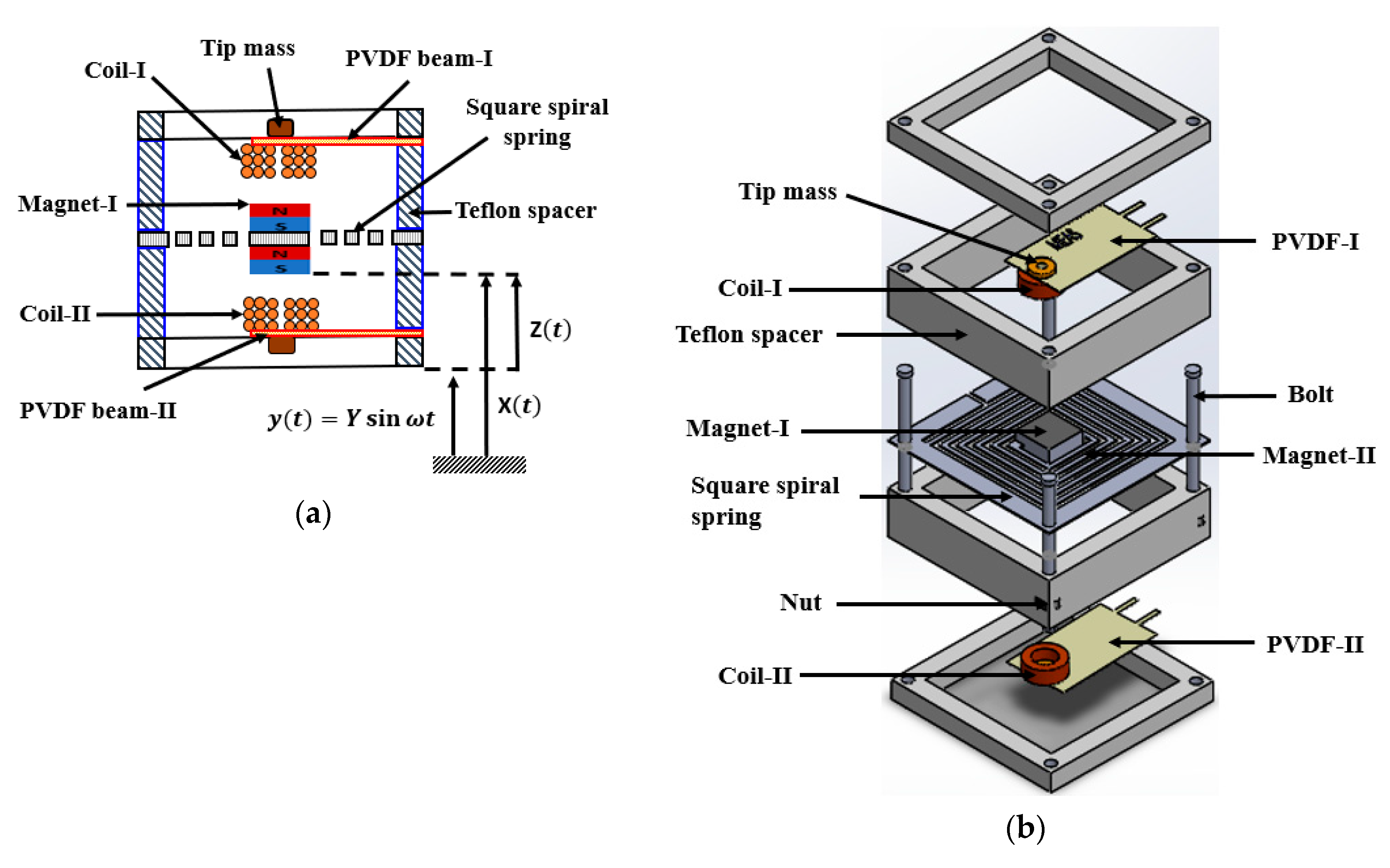
2.1. Design and Working Principle

Figure 1a illustrates the vertical cross-section of the developed HIEH; comprising a set of wound coils, a set of magnets, a couple of Polyvinylidene fluoride (PVDF) cantilever beams and a square spiral planar spring (steel), in the middle of the device. An exploded view of the HIEH is given in Figure 1b. In the device, the middle portion (platform) of the square spiral planar spring holds on to two permanent magnets as proof mass; both on top and bottom sides, right at the center of the spring. The spring follows a square spiral pattern, in order to increase the length of the beam and thus, results in lowering the resonant frequency to the minimum possible value, whilst attaining the walking step frequency. Notably, 2 mm nuts and bolts in Teflon spacers are used to fix the spring firmly in the device. The upper and lower flexible PVDF cantilever beams are firmly clamped to the spacers, with wound coils attached to their tips, such that the wound coils are just in-line, and as close to the magnetic masses to ensure maximum flux density over the coils. The tip mass of the PVDF cantilever (coil and brass) acts as a driving force and lowers the resonant frequencies of the beams. Both the beams are provided with individual supporting spacers, to add gaps between the coils and magnets. The PVDF beams are tuned at different resonant frequencies to the square spiral planar spring, to ensure multi resonant states and the wide operation frequency of the harvester.
The working principle of the developed HIEH is based on piezo-electromagnetic coupling, using piezoelectric and electromagnetic transductions. When the harvester experiences an external excitation, the intermediate spiral planar spring starts oscillating due to the proof magnetic mass, which changes the magnetic flux density across the wound coils on the upper and lower flexible PVDF cantilever beams. As a result, an electromotive force is induced, according to Faraday law of electromagnetism. At the same time, the upper and lower PVDF cantilever beams also experience base accelerations, which produce voltage based on PE effect (dipoles alignment due to beam’s deformation induced voltage in the PVDF material) and deliver peak power values at resonant frequencies of the upper and lower cantilevers. The PE part of the harvester can be considered as a current source, because of the large internal resistance, and hence, has low power, whilst the EM part is a voltage source with small internal resistance [52].

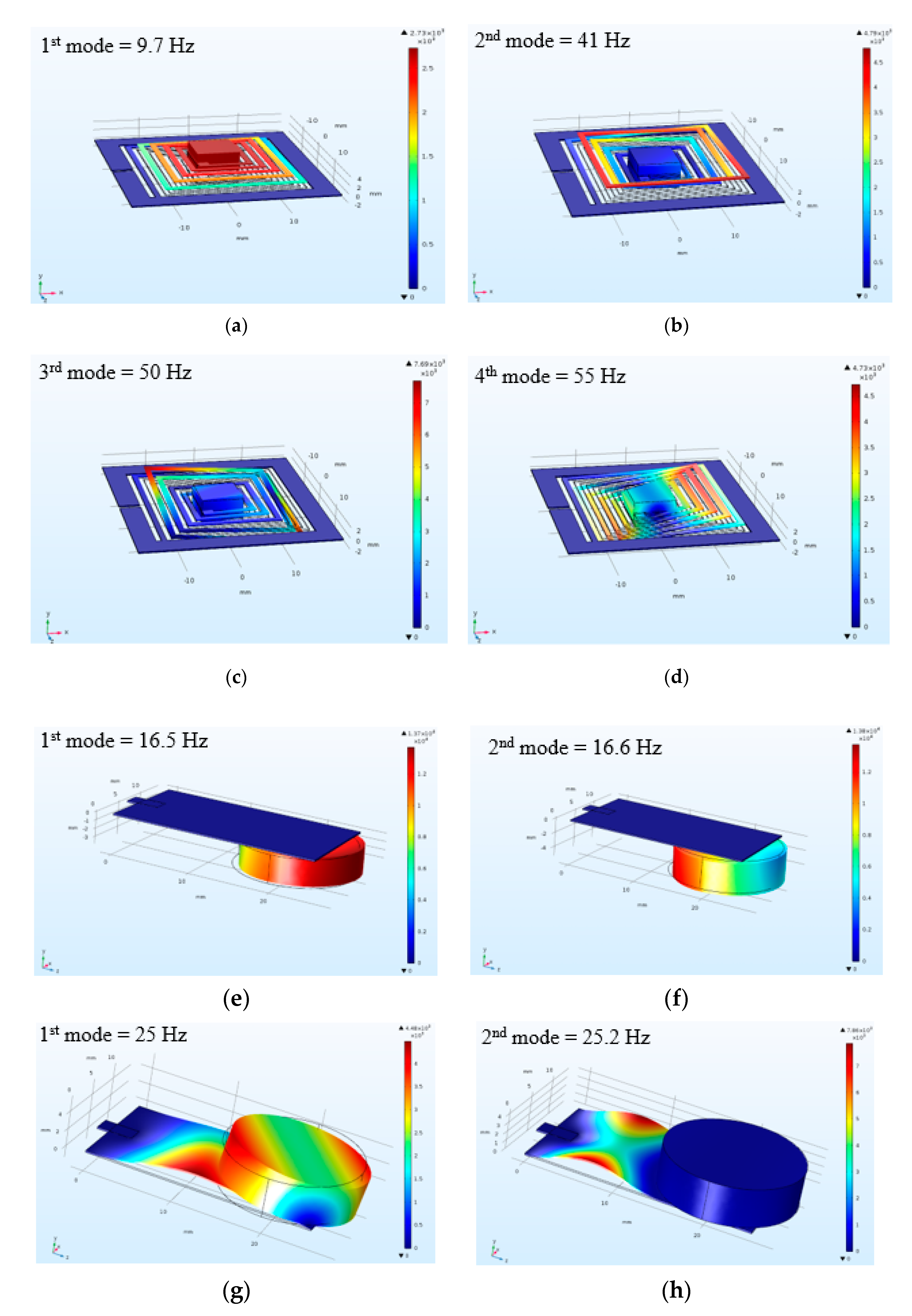
2.2. Finite Element Analysis for the Proposed HIEH

The HIEH proposed in this work is a resonant-type multi-mode (http://bit.ly/3cN2tbx) system, with peak output power at different resonant frequencies. The Eigen frequency modal analysis conducted in COMSOL Multiphysics® software is shown in Figure 2. The suspended square planar spring was designed holding desk magnets at the center and fixed constraints were applied to the spring at outer edges. The magnets were united with the spring and the model was meshed to compute for the Eigenfrequencies. The resonant frequencies of the HIEH are obtained at 9.6 Hz (1st mode), 41 Hz (2nd mode), 51 Hz (3rd mode) and 55 Hz (4th mode). In the first mode, the central platform of the spring holding magnetic masses and the adjacent solid rings were moving at maximum amplitude, as shown in Figure 2a. At 41 Hz, the 4th and 5th rings in the square moved at maximum displacement, Figure 2b. The displacement shifted towards the corner of the spring at higher frequencies of 50 Hz and 55 Hz, as depicted in Figure 2c,d, respectively. However, the upper PVDF, Figure 2e,f, and lower PVDF, Figure 2g,h cantilever beams holding wound coils resonate at 16.5 Hz and 25 Hz respectively, and produced peak output across the upper and lower coil. The PVDF beams, due to the tip mass of the wound coils and the gap between coils and magnets (4 mm), do not interact with the magnets.

2.3. Electromechanical Model

The proposed HIEH can be modeled as lumped mass linear system, with the equation of motion for a harvester experiencing base excitations [33,53,54].
m z ¨ + c z ˙ + F r = m y ¨
In Equation (1), m is mass of the magnets, z is the relative displacement between magnets and coils, F r is the restoring force (spring force, kz) on the moving magnets, and y is the displacement of the harvester’s base (frame). Moreover, c T is the total damping coefficient, which is mechanical ( c m ) and electrical ( c e ) damping c T = c m + c e . Electrical damping coefficient c e can be expressed as c e = α 2 / R , where α is the electromechanical coupling coefficient and R is the sum of internal impedance and load resistance across the harvester’s coil [33].
The dynamic behavior of the spring-magnets assembly mainly depends on the magnetic mass, damping coefficient, and spring constant k [32]
k = G d 4 8 n D 3
where G is shear stress of the spring material, d is the spring sheet diameter, n is the number of turns in the spring and D is the mean spring diameter.
When the harvester is exposed to base excitation y ( t ) , as shown in Figure 3, the relative displacement ( Z ) of magnetic masses attached to the spring can be derived in terms of base excitation [55]
Z = Y ω 2 ω 2 n ( 1 ( ω ω n ) 2 ) 2 + ( 2   ξ T   ω ω n ) 2
and amplitude ( U ) of relative velocity
U = A ω ω 2 n ( 1 ( ω ω n ) 2 ) 2 + ( 2   ξ T   ω ω n ) 2
In terms of forcing frequency ω , input vibration amplitude Y , damping ratio ξ T and resonant frequency ω n of the harvester [56].
Generated voltage as a function of frequency, in terms of the relative velocity ( G ) of the magnet, magnetic flux density ( B z ) and the area ( S ) of coil turns, can be expressed [57] according to Faraday’s law of electromagnetic induction.
V ( ω ) = G d B z d x S
The magnitude of EMF across the coils is directly proportional to the change of magnetic flux through the coil [58]
ε = Y 2 ξ ω n = m Y d
where d is the damping constant in damping ratio Equation (6). It is evident that ε is directly related to m in Equation (6), and hence, an increase in the proof mass ( m ) will result in increasing the EMF.
Magnetic flux density B x , along the normal line to the center of the magnet [59],
B x = B r 2 ( x + H m ( x + H m ) 2 + ( r m ) 2 x ( x 2 + r m 2 ) )
depends on the height of magnet H m , flux density B r , radius r m of magnet and distance x from the magnet, which can be modified to Equation (8)
d B x d x = B r 2 ( ( D 1 + H m ( D 1 + H m ) 2 + ( r m ) 2 ( D 1 + H m ) 2 ( D 1 + H m ) 2 + ( r m ) 2 3 ) ( 1 D 1 2 + r m 2 D 1 2 D 1 2 + r m 2 3 ) )
for multi-layered wound coil with N number of turns, inner radius r p , and diameter d w of the wire. Area sum, S , can be obtained by taking the derivative for x and putting its value in D 1 (gap between coil and magnet).
S = i = 1 N S i i = 1 N π r i 2
For a multi-layered wound coil as shown in Figure 4,
r i = r p + ( i 1 2 ) d w
the time response of voltage gain can be converted to the frequency domain
V ( ω ) = G i = 0 n B r 2 ( ( D i + H m ( D i + H m ) 2 + ( r m ) 2 ( D i + H m ) 2 ( D i + H m ) 2 + ( r m ) 2 3 ) ( 1 D i 2 + r m 2 D 0 2 D i 2 + r m 2 3 ) ) S
as function of D i , distance of a single layer from the magnet.
For the resistor-connected circuit, the voltage across load resistance can also be
V R ( t ) = I R ( t ) R
and peak voltage across an optimum load [60].
V L p e a k = ( R L R L + R C ) V p e a k
Power across a resistor, P R
P R ( t ) = V R ( t ) I R ( t )
and load power, P L across load resistance, R L
P L = V L 2 2 R L
depends on load resistance R L and coil impedance R C [61].
Maximum power output from the electromagnetic part at resonance [62] is,
P = ( N l B Y ) 2 16 ξ t 2 R c
where N represents the number of coil turns, l is the length of copper wire, B is electromagnetic induction, Y is the displacement of the spring and R c is the coil resistance.
For load resistance equal to the source internal resistance connected across the piezoelectric plate
V p ( t ) = V R ( t )
and
I R ( t ) = ω Q p ( t )
where Q p is the charge on piezoelectric plate in Equation (18), and maximum power [63] is
P = V 2 L R L

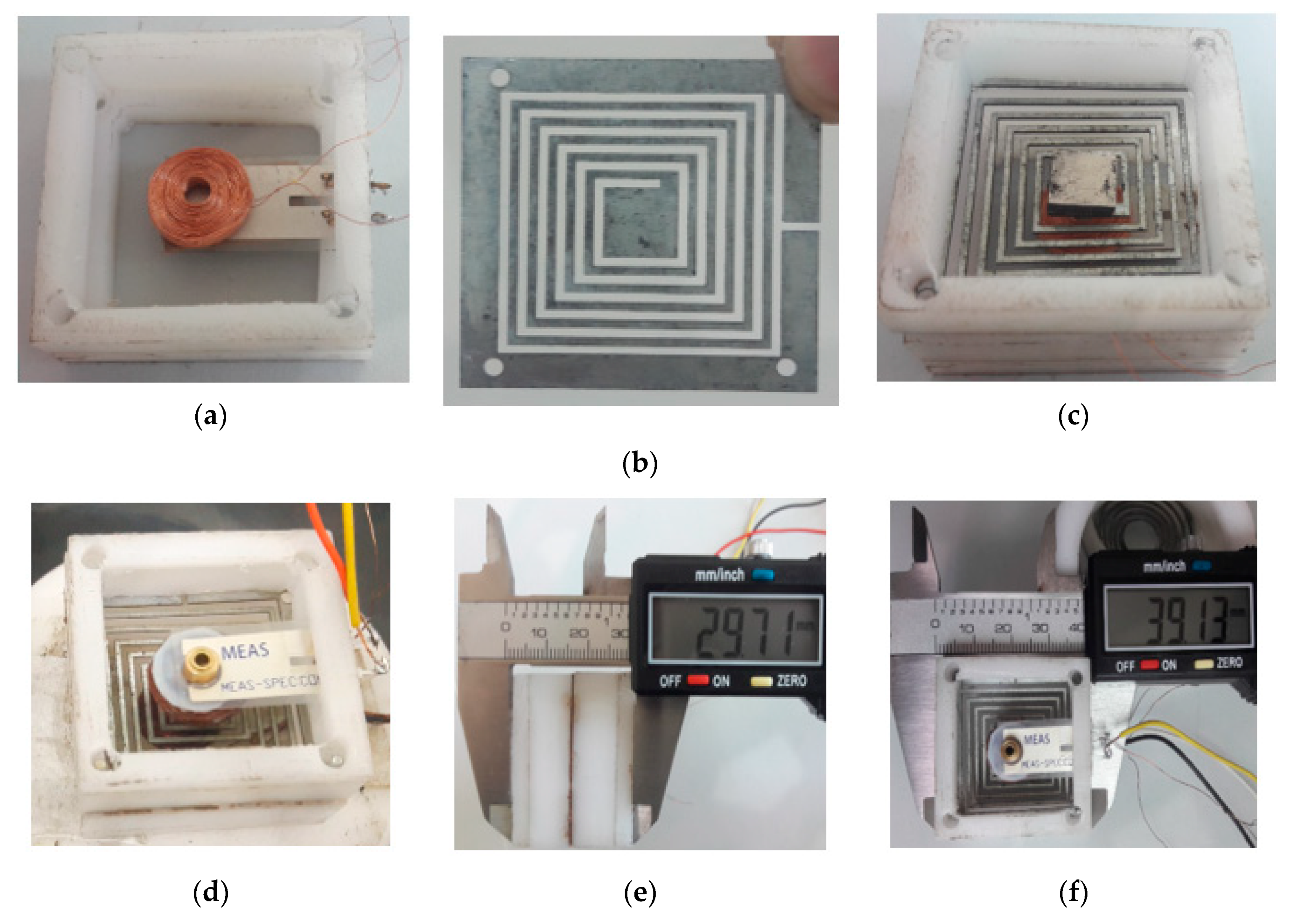
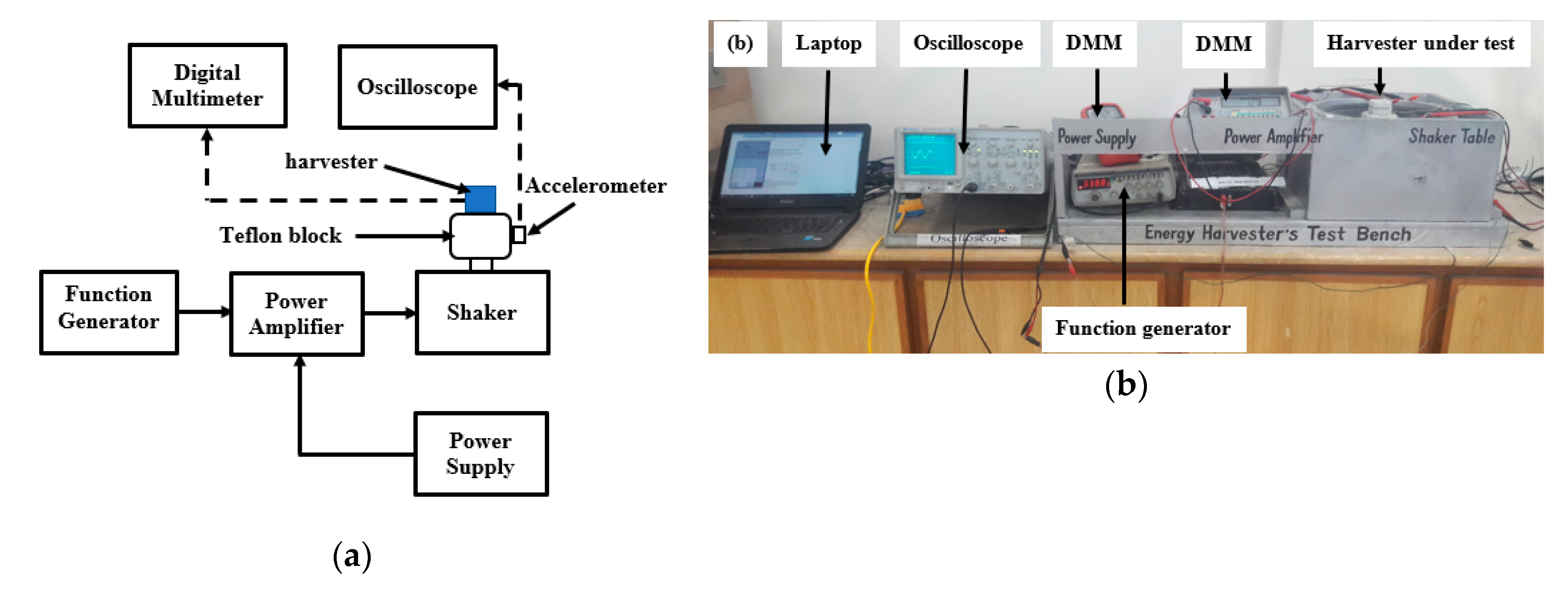
3. Prototype Fabrication and Experimental Setup

A centimeter-scale hybrid PE-EM insole energy harvester fabricated in this work is as shown in Figure 5. The intermediate square spiral planar spring of dimensions 38 mm × 38 mm × 0.26 mm was fabricated from galvanized (GI) steel (Shanghai Metal Co., China), using computer numerical controlled, wire-cut electrical discharge machining (CNC-EDM). The fabricated spiral spring consists of five turns, having a 1 mm wire width and 1 mm gap between individual spring turns. Furthermore, a platform (8 mm × 8 mm) is provided with the inner turn of the spring for magnets. Two magnets of sizes 8 mm × 8 mm × 2 mm are fixed (self-clamped) on the top and bottom sides of the central platform of the square spiral spring, Figure 5b. The spiral shape of the spring kept the size of the device to the minimum; considering the size constraints of the insole, whilst allowing the extension of the beam length to a maximum length of 409 mm, in order to achieve resonance at low walking frequency. The intermediate square spiral spring is fixed on its sides, between Teflon spacers with the same dimensions as the spring; fixing all of its sides, whilst allowing its center to oscillate freely on exposure to external excitations, as shown in Figure 5c.
Upper and lower PVDF (Meas-spec) polymers (25 mm × 13 mm) were used as cantilever beams. Two wounds of conducting coils (Φ 12 mm × 4 mm): coil I and coil II, were produced from 80 µm enameled copper wire, and fixed to the under-side (to face magnets), at the tip of cantilever beams, and just in-line and close to the respective (upper and lower) magnets, for maximum power generation. The PVDF-I and PVDF-II were securely clamped by the upper and lower Teflon spacers; with its terminals left outside to allow easy electrical connections and the measurement of output signals, Figure 5d.
The harvester is assembled using 2 mm small nut and bolts. The developed HIEH comprised of an upper hybrid generator (PVDF-I and magnet-coil-I) and a lower hybrid generator (PVDF-II and magnet-coil-II). The geometric parameters of the developed HIEH are listed in Table 3.
The output performance of the HIEH was tested inside the laboratory, using the experimental setup: a schematic diagram is depicted in Figure 6a and the developed experimental setup is shown in Figure 6b. The harvester was firmly fixed on the vibration shaker’s table, with the shaker used to generate sinusoidal input excitations of varying acceleration intensities from 0.1 g to 0.6 g, and frequency from 1 Hz to 115 Hz. A 3-axis accelerometer (Model: EVALADXL335Z, Norwood U.S.A) was attached to the shaker’s table, to record the different base acceleration levels of input frequency signals coming from the function generator (Model: GFG 8020H, GW Instek, New Taipei, Taiwan). A 12 V, DC power supply (Model: GT-41132, GlobTek, Inc., Japan) was used to supply power to the amplifier (Model RM–AT2900, Rock Mars, United Arab Emirates), which magnifies and regulates signals to the vibration shaker, in order to excite the harvester. Moreover, a digital oscilloscope (Model: GDS-2204A, GW Instek, New Taipei, Taiwan) and digital multimeters (DMM) (Model: UT81A/B, Uni-Trend Technology, China) were used to measure and analyze output signals from the accelerometer and the harvester, respectively.
In the upper and lower hybrid generators, both the PE and EM outputs were integrated. Both outputs are in-phase and were connected in series resulting in improved output voltage, which was nearly equal to the sum of the individual output voltages. To obtain the optimum power for the HIEH, the output voltage was measured across different external load resistances.

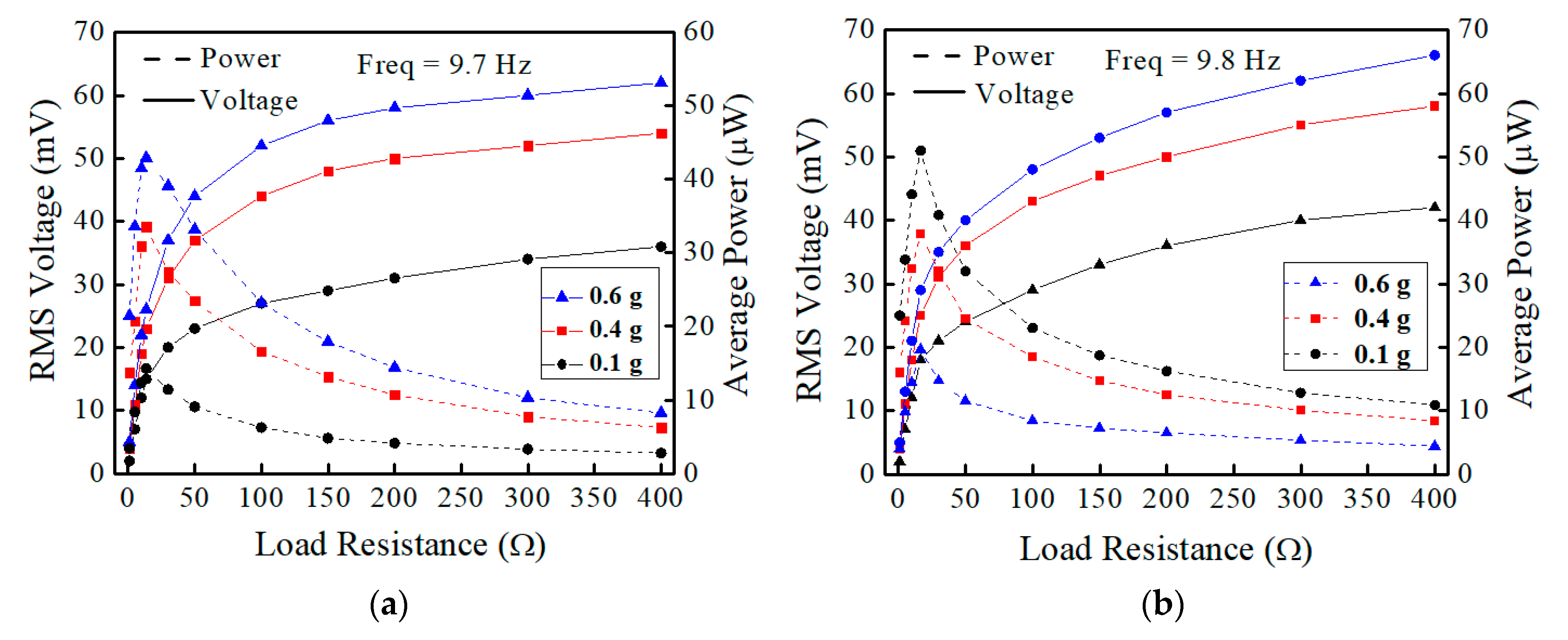
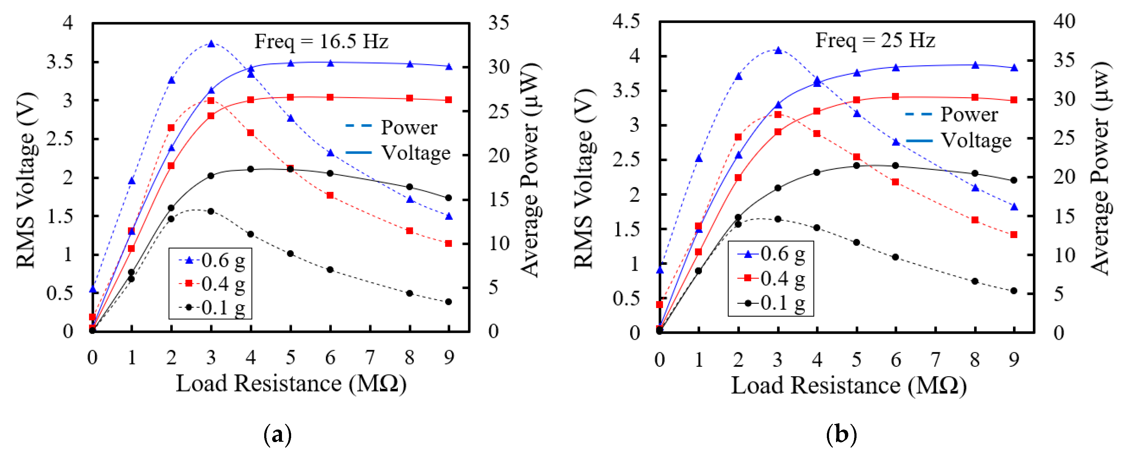
4. Experimental Results

The HIEH was characterized inside the laboratory under sinusoidal input excitation for a frequency sweep (1–115 Hz) of varying acceleration amplitudes from 0.1 to 0.6 g. Notably, Figure 7a,b show the output voltage of the upper and lower hybrid generators for varying frequencies at 0.1g, 0.4 g, and 0.6 g acceleration levels. The device operates in a wide operating frequency of 45 Hz, and exhibits multi-resonant states, corresponding to the resonant frequencies of the intermediate square spiral spring, the upper, and lower cantilever beams under forward frequency sweep. The spiral spring responds to as low-frequency oscillations as 5 Hz, and resonates at 9.7 Hz, producing the highest no-load voltage of 1.41 V across the lower hybrid generator under 0.6 g base acceleration, as illustrated in Figure 7a. Moreover, the square spiral spring excites at 41 Hz, 50 Hz and 55 Hz, producing second and third peak voltages of 4.55 V and 1.8 V, respectively, at the second and third mode of vibration. Furthermore, the lower PVDF cantilever resonates at 25 Hz and produces an open-circuit voltage of 1.71 V under 0.6 g base acceleration across the lower hybrid harvester. The upper PVDF cantilever excites at 16.5 Hz and delivered maximum open-circuit voltage of 5.64 V across the upper hybrid generator under 0.6 g, as depicted in Figure 7b. The upper and lower hybrid generators are also tested across matching impedances (optimum loads), under different acceleration levels and input frequencies, as represented by the solid lines in Figure 7a,b. The peak voltage levels of 1.55 V and 1.71 V under 0.6 g are delivered to the optimum resistances. The vibration amplitude decreases with an increase in system damping, and the total power is not merely sum of the piezoelectric and electromagnetic power, but rather a function of the total damping.
Figure 8a,b show the variation of RMS voltage and average power levels as a function of different load resistances, between 5 Ω and 400 Ω, connected across coil-I and coil-II, respectively. The HIEH is kept oscillating at first resonant frequency of 9.7 Hz and is subjected to different base accelerations. The behavior of the upper and lower electromagnetic generators is identical, but with peak voltages at different base accelerations, as depicted in Figure 8. With increasing load across the upper and lower EM generators, output RMS voltage initially increases considerably before becoming gradually flattered at relatively higher loads. Average power, however, increases until it reaches the highest value at the optimum load (13.5 Ω for coil-I and 16.5 Ω for coil-II), before decreasing exponentially. With the average power obtained from RMS voltage [64]; using equation P = V R M S 2 / R L , maximum powers are delivered across both coils, with load resistances equal to the coil’s internal resistance, which satisfies maximum power transfer [65].
Figure 9a,b indicate the dependence of load voltage and load power on load resistance values across PVDF terminals. Under 3 MΩ load resistance, PVDF-I and PVDF-II show the highest average power when excited at resonant frequencies of 16.5 and 25 Hz, respectively. RMS voltage and average power increase with increasing amplitude of base acceleration, as depicted in Figure 9a, and highest load voltage of 3.4 V, was obtained across PVDF-I at 16.5 Hz, under 0.6 g at a loading resistance of 9 M Ω. As demonstrated in Figure 9b, the RMS voltage and average power increase with an increase in base acceleration and the peak power reaches 36.3 µW across 3 MΩ load resistance, at resonant frequency of 25 Hz of the lower cantilever beam.
The power produced by the HIEH was demonstrated by charging a 100 µF capacitor (http://bit.ly/2TB9V1W), and on successful integration into the sole of a commercial shoe. The harvester was connected to a full-wave rectifier and charged a 100 µF capacitor from 0 to ~ 1.8 V, with a normal walk of 8 min from the piezoelectric portion, Figure 10a. The same capacitor was charged up to 2.9 V by the hybrid piezoelectric-electromagnetic coupling at the same time, Figure 10b. The hybrid harvester, when integrated into a commercial shoe, as shown in Figure 10c maintained a stable voltage supply from 5 to 50 Hz and a better-charging performance than the individual EM or PE unit, Figure 10d.

5. Comparison and Discussion

Most of the insole energy harvesters reported in literature are either piezoelectric, electromagnetic, triboelectric or hybrid, by combining two or three of the mentioned harvesting techniques. The developed HIEH is compared with previously developed harvesters, based on important parameters such as resonant frequency, acceleration level, the device’s internal resistance, voltage and power generation capabilities, device size and operation mechanism. Piezoelectric transduction and triboelectrification are used by most of the reported insole energy harvesters, with a few utilizing electromagnetic inductions as listed in Table 4. The electrostatic mechanism, however, is rarely used in the insole, because of the initial charge requirement in these harvesters [66]. Different piezoelectric polymers, such as PVDF, and piezoelectric ceramic, such as PZT and aluminium nitride (AlN), are commonly used in insoles with multiple beam geometries. Triboelectric materials with different patterns (curved, parallel and zigzag) have also been increasingly utilized in insole applications, due to their lower resonant frequencies, strong electronegativity, cost-effectiveness, robust and simple integration. In EM insole energy harvesters, the coil is extensively made of copper (Cu) wire because of good conductivity, ductility, and tensile strength, while aluminum (Al) is used for the suspension unit, owing to its good flexibility, non-permanent deformation, and good fatigue strength. Combining two or more harvesting mechanisms in a hybrid system is a recent research interest for the sustainable drive of microelectronics [67]. The resonant frequencies of the reported insole energy harvesters, shown in Table 4, range from 3–50 Hz with the highest operating frequency of 45 Hz, and the base accelerations to which these harvesters were subjected, were 0.1–1.0 g. The reported triboelectric insole energy harvesters generally generated more voltage levels (75–134 V) than piezoelectric (20–30 V) and electromagnetic (0.22–0.24 V) insole energy harvesters. However, the internal impedance of the piezoelectric (400 kΩv–2 MΩ) and triboelectric (15–120 MΩ) EHs are generally more than the electromagnetic (12–240 Ω) EHs. Therefore, triboelectric (1.67–84.7 µW) and piezoelectric (30.55–800 µW) generators produce relatively less power than electromagnetic (61.3–1150 µW) generators. The powers generated by the hybrid insole energy harvesters (109–32,000 µW) are more than the standalone piezoelectric (4.9–800 µW), electromagnetic (61.3–1150 µW) and triboelectric (1.67–11,700 µW) EHs, due to the combined transduction mechanisms. The output powers of piezoelectric and electromagnetic generators depend upon the design and efficiency of the transducer. Normally, piezoelectric transducers have large optimal load resistances and hence, high voltage output. On the other hand, electromagnetic energy harvesters have small optimal resistances, and low voltage output.
The HIEH developed in this work is a low-frequency resonant-type multimodal system, being able to operate at wide operation frequency (9–55 Hz), and is compared with the reported piezoelectric, electromagnetic, triboelectric and hybrid insole energy harvesters. The harvester was operated for a long time inside the sole of a shoe, with sufficient power levels at multi-resonant states, which shows its mechanical durability. Having dual transduction mechanisms, multi resonant states, compact size, lightweight, comparatively lower internal impedance and being able to operate at low-frequency vibrations makes it a power-efficient system.

6. Conclusions

A hybrid insole energy harvester (HIEH), based on piezoelectric-electromagnetic transduction, has been developed and tested. The HIEH is able to power wearable electronics, by scavenging biomechanical energy during walking. The harvester, which constitutes an upper and lower hybrid piezoelectric-electromagnetic generator, is based on effective conjunction of piezoelectricity and electromagnetic induction, and generated an overall peak power of 109 µW and 70 µW, corresponding to power densities of 2.47 µW/cm3 and 1.58 µW/cm3, respectively. Considering the available space inside the shoe sole and the walking steps frequency, the devised HIEH is designed as a compact structure and exhibited six resonant states in the lower frequency range, resulting in a wider operation frequency of approximately 45 Hz. Furthermore, the hybrid generator has a better charging performance than the standalone units and can supply power sustainably to wearable electronic gadgets, like a pedometer, smartwatch, and wireless body monitoring sensors. The intermediate spring is holding magnetic masses on top and bottom sides and the magnets are inline and close to the wound coils attached to the PVDF beams. On subjecting to the input sinusoidal signals on the shaker’s table, first, the square spiral spring starts oscillations at as low frequency as 5 Hz and reaches its first resonance at 9.7 Hz. The upper and lower PVDF beams resonate at 16.5 and 25 Hz, producing a peak power of 33 µW and 37 µW across stretchable PVDF cantilevers under 0.6 g, across matching impedance of 3 MΩ. The energy was stored using a 100 µF capacitor through walking, and as compared to the piezoelectric unit, the hybrid harvester charged the same capacitor 30% more voltage at the same time. The charging capacity of the HIEH shows that stored energy can be used to operate microelectronics.
As future directions, to optimize the harvester, we are working on
  • Tuning the higher frequencies (25, 50 and 51 Hz) by frequency-up-conversion approach to further improve the device performance in low-frequency human motion.
  • Maximizing the conversion efficiency with an improved power conditioning circuit, using a voltage doubler circuit, and rectifier with lowest possible drop-down voltage.
  • A full-packaged frame for the HIEH to cover the PVDF cantilever beams and make the harvester a more flexible system for wearable applications.
  • Fatigue analysis of spiral-spring material.

Author Contributions

Conceptualization, M.I.; methodology, M.I., M.M.N. and F.U.K.; software, M.I., M.M.N.; validation, M.I.; formal analysis, A.I., B.A., P.E.A. and Q.C.; writing—original draft preparation, M.I.; writing—review and editing, M.M.N., F.U.K., M.I, P.E.A., Q.C., A.I. and B.A.; supervision, M.M.N., P.E.A. and Q.C.; All authors have read and agreed to the published version of the manuscript.

Funding

This research is supported by Universiti Brunei Darussalam’s University Research Grant Number UBD/RSCH/1.3/FICBF(b)/2019/003.

Acknowledgments

The authors would like to acknowledge Sensors and Energy Harvesting Systems Research Lab (SEHSR Lab), Department of Mechatronics, University of Engineering and Technology, Peshawar, Pakistan for providing access to the lab.

Conflicts of Interest

The authors declare no conflict of interest.

References

  1. Lee, H.; Choi, T.K.; Lee, Y.B.; Cho, H.R.; Ghaffari, R.; Wang, L.; Choi, H.J.; Chung, T.D.; Lu, N.; Hyeon, T.; et al. A graphene-based electrochemical device with thermoresponsive microneedles for diabetes monitoring and therapy. Nat. Nanotechnol. 2016, 11, 566–572. [Google Scholar] [CrossRef] [PubMed]
  2. Bai, P.; Zhu, G.; Jing, Q.; Yang, J.; Chen, J.; Su, Y.; Ma, J.; Zhang, G.; Wang, Z.L. Membrane-Based Self-Powered Triboelectric Sensors for Pressure Change Detection and Its Uses in Security Surveillance and Healthcare Monitoring. Adv. Funct. Mater. 2014, 24, 5807–5813. [Google Scholar] [CrossRef]
  3. Tian, Z.; He, J.; Chen, X.; Wen, T.; Zhai, C.; Zhang, Z.; Cho, J.; Chou, X.; Xue, C. Core-shell coaxially structured triboelectric nanogenerator for energy harvesting and motion sensing. RSC Adv. 2018, 8, 2950–2957. [Google Scholar] [CrossRef] [Green Version]
  4. Larcher, D.; Tarascon, J.M. Towards greener and more sustainable batteries for electrical energy storage. Nat. Chem. 2015, 7, 19–29. [Google Scholar] [CrossRef] [PubMed]
  5. Lisbona, D.; Snee, T. A review of hazards associated with primary lithium and lithium-ion batteries. Process Saf. Environ. Prot. 2011, 89, 434–442. [Google Scholar] [CrossRef]
  6. Recham, N.; Chotard, J.N.; Dupont, L.; Delacourt, C.; Walker, W.; Armand, M.; Tarascon, J.M. A 3.6 v lithium-based fluorosulphate insertion positive electrode for lithium-ion batteries. Nat. Mater. 2010, 9, 68–74. [Google Scholar] [CrossRef] [PubMed]
  7. Fan, K.; Chang, J.; Chao, F.; Pedrycz, W. Design and development of a multipurpose piezoelectric energy harvester. Energy Convers. Manag. 2015, 96, 430–439. [Google Scholar] [CrossRef]
  8. Armand, M.; Tarascon, J.M. Building better batteries. Nature 2008, 451, 652–657. [Google Scholar]
  9. Han, S.; Kim, J.; Won, S.M.; Ma, Y.; Kang, D.; Xie, Z.; Lee, K.-T.; Chung, H.U.; Banks, A.; Min, S.; et al. Battery-free, wireless sensors for full-body pressure and temperature mapping. Sci. Transl. Med. 2018, 10. [Google Scholar] [CrossRef] [Green Version]
  10. Shi, B.; Liu, Z.; Zheng, Q.; Meng, J.; Ouyang, H.; Zou, Y.; Jiang, D.; Qu, X.; Yu, M.; Zhao, L.; et al. Body-Integrated Self-Powered System for Wearable and Implantable Applications. ACS Nano 2019, 13, 6017–6024. [Google Scholar] [CrossRef]
  11. Guo, H.; Chen, J.; Yeh, M.H.; Fan, X.; Wen, Z.; Li, Z.; Hu, C.; Wang, Z.L. An ultrarobust high-performance triboelectric nanogenerator based on charge replenishment. ACS Nano 2015, 9, 5577–5584. [Google Scholar] [CrossRef] [PubMed]
  12. Khan, F.U.; Ahmad, S. Flow type electromagnetic based energy harvester for pipeline health monitoring system. Energy Convers. Manag. 2019, 200, 112089. [Google Scholar] [CrossRef]
  13. Zheng, L.; Cheng, G.; Chen, J.; Lin, L.; Wang, J.; Liu, Y.; Li, H.; Wang, Z.L. A Hybridized Power Panel to Simultaneously Generate Electricity from Sunlight, Raindrops, and Wind around the Clock. Adv. Energy Mater. 2015, 5, 1–8. [Google Scholar] [CrossRef]
  14. Kymissis, J.; Kendall, C.; Paradiso, J.; Gershenfeld, N. Parasitic power harvesting in shoes. Int. Symp. Wearable Comput. Dig. Pap. 1998, 1998, 132–139. [Google Scholar]
  15. Park, J.H.; Wu, C.; Sung, S.; Kim, T.W. Ingenious use of natural triboelectrification on the human body for versatile applications in walking energy harvesting and body action monitoring. Nano Energy 2019, 57, 872–878. [Google Scholar] [CrossRef]
  16. Lukowicz, P.; Anliker, U.; Ward, J.; Troster, G.; Hirt, E.; Neufelt, C. AMON: A wearable medical computer for high risk patients. In Proceedings of the International Symposium on Wearable Computers, Seattle, WA, USA, 10 October 2002; pp. 133–134. [Google Scholar]
  17. Nagae, D.; Mase, A. Measurement of heart rate variability and stress evaluation by using microwave reflectometric vital signal sensing. Rev. Sci. Instrum. 2010, 81, 94301. [Google Scholar] [CrossRef] [Green Version]
  18. Steele, B.G.; Belza, B.; Cain, K.; Warms, C.; Coppersmith, J.; Howard, J.E. Bodies in motion: Monitoring daily activity and exercise with motion sensors in people with chronic pulmonary disease. J. Rehabil. Res. Dev. 2003, 40, 45–58. [Google Scholar] [CrossRef]
  19. Cook, D.J.; Thompson, J.E.; Prinsen, S.K.; Dearani, J.A.; Deschamps, C. Functional recovery in the elderly after major surgery: Assessment of mobility recovery using wireless technology. Ann. Thorac. Surg. 2013, 96, 1057–1061. [Google Scholar] [CrossRef]
  20. Jeong, S.Y.; Hwang, W.S.; Cho, J.Y.; Jeong, J.C.; Ahn, J.H.; Kim, K.B.; Hong, S.D.; Song, G.J.; Jeon, D.H.; Sung, T.H. Piezoelectric device operating as sensor and harvester to drive switching circuit in LED shoes. Energy 2019, 177, 87–93. [Google Scholar] [CrossRef]
  21. Qian, F.; Xu, T.B.; Zuo, L. Design, optimization, modeling and testing of a piezoelectric footwear energy harvester. Energy Convers. Manag. 2018, 171, 1352–1364. [Google Scholar] [CrossRef]
  22. Iqbal, M.; Nauman, M.M.; Cheok, Q.H.N.; Abas, A.E.P.; Ahmad, I. Design and modeling of a smart insole hybrid energy harvester. In Proceedings of the IET Conference Publications, Institution of Engineering and Technology, Bandar Seri Begawan, Brunei, 12–14 November 2018; p. 4. [Google Scholar]
  23. Fan, K.; Yu, B.; Zhu, Y.; Liu, Z.; Wang, L. Scavenging energy from the motion of human lower limbs via a piezoelectric energy harvester. Int. J. Mod. Phys. B 2017, 31, 1741011. [Google Scholar] [CrossRef]
  24. Li, H.; Tian, C.; Deng, Z.D. Energy harvesting from low frequency applications using piezoelectric materials. Appl. Phys. Rev. 2014, 1, 1–20. [Google Scholar] [CrossRef] [Green Version]
  25. Moro, L.; Benasciutti, D. Harvested power and sensitivity analysis of vibrating shoe-mounted piezoelectric cantilevers. Smart Mater. Struct. 2010, 19, 115011. [Google Scholar] [CrossRef]
  26. Pillatsch, P.; Yeatman, E.M.; Holmes, A.S. A piezoelectric frequency up-converting energy harvester with rotating proof mass for human body applications. Sens. Actuators A Phys. 2014, 206, 178–185. [Google Scholar] [CrossRef]
  27. Fan, K.; Liu, Z.; Liu, H.; Wang, L.; Zhu, Y.; Yu, B. Scavenging energy from human walking through a shoe-mounted piezoelectric harvester. Appl. Phys. Lett. 2017, 110, 143902. [Google Scholar] [CrossRef]
  28. Xie, L.; Cai, M. Increased piezoelectric energy harvesting from human footstep motion by using an amplification mechanism. Appl. Phys. Lett. 2014, 105, 1–5. [Google Scholar] [CrossRef]
  29. Li, K.; He, Q.; Wang, J.; Zhou, Z.; Li, X. Wearable energy harvesters generating electricity from low-frequency human limb movement. Microsyst. Nanoeng. 2018, 4, 24. [Google Scholar] [CrossRef]
  30. Saha, C.R.; O’Donnell, T.; Wang, N.; McCloskey, P. Electromagnetic generator for harvesting energy from human motion. Sens. Actuators A Phys. 2008, 147, 248–253. [Google Scholar] [CrossRef]
  31. von Büren, T. Body-Worn Inertial Electromagnetic Micro-Generators. Ph.D. Thesis, Swiss Fedral Institute of Technology Zurich, Zürich, Switzerland, 2006. [Google Scholar]
  32. Halim, M.A.; Cho, H.; Park, J.Y. Design and experiment of a human-limb driven, frequency up-converted electromagnetic energy harvester. Energy Convers. Manag. 2015, 106, 393–404. [Google Scholar] [CrossRef]
  33. Wang, W.; Cao, J.; Zhang, N.; Lin, J.; Liao, W.H. Magnetic-spring based energy harvesting from human motions: Design, modeling and experiments. Energy Convers. Manag. 2017, 132, 189–197. [Google Scholar] [CrossRef]
  34. Zhang, K.; Wang, X.; Yang, Y.; Wang, Z.L. Hybridized Electromagnetic-Triboelectric Nanogenerator for Scavenging Biomechanical Energy for Sustainably Powering Wearable Electronics. ACS Nano 2015, 9, 3521–3529. [Google Scholar] [CrossRef] [PubMed]
  35. Lu, B.; Chen, Y.; Ou, D.; Chen, H.; Diao, L.; Zhang, W.; Zheng, J.; Ma, W.; Sun, L.; Feng, X. Ultra-flexible Piezoelectric Devices Integrated with Heart to Harvest the Biomechanical Energy. Sci. Rep. 2015, 5, 1–9. [Google Scholar] [CrossRef] [PubMed] [Green Version]
  36. Lu, Y.; Cottone, F.; Boisseau, S.; Marty, F.; Galayko, D.; Basset, P. A nonlinear MEMS electrostatic kinetic energy harvester for human-powered biomedical devices. Appl. Phys. Lett. 2015, 107, 253902. [Google Scholar] [CrossRef]
  37. Wu, S.; Luk, P.C.K.K.; Li, C.; Zhao, X.; Jiao, Z.; Shang, Y. An electromagnetic wearable 3-DoF resonance human body motion energy harvester using ferrofluid as a lubricant. Appl. Energy 2017, 197, 364–374. [Google Scholar] [CrossRef]
  38. Wang, Z.L. Triboelectric nanogenerators as new energy technology for self-powered systems and as active mechanical and chemical sensors. ACS Nano 2013, 7, 9533–9557. [Google Scholar] [CrossRef]
  39. Mahmud, A.; Khan, A.A.; Islam, S.; Voss, P.; Ban, D. Integration of organic/inorganic nanostructured materials in a hybrid nanogenerator enables efficacious energy harvesting via mutual performance enhancement. Nano Energy 2019, 58, 112–120. [Google Scholar] [CrossRef]
  40. Wang, X.; Niu, S.; Yi, F.; Yin, Y.; Hao, C.; Dai, K.; Zhang, Y.; You, Z.; Wang, Z.L. Harvesting Ambient Vibration Energy over a Wide Frequency Range for Self-Powered Electronics. ACS Nano 2017, 11, 1728–1735. [Google Scholar] [CrossRef]
  41. Chen, J.; Zhu, G.; Yang, W.; Jing, Q.; Bai, P.; Yang, Y.; Hou, T.C.; Wang, Z.L. Harmonic-resonator-based triboelectric nanogenerator as a sustainable power source and a self-powered active vibration sensor. Adv. Mater. 2013, 25, 6094–6099. [Google Scholar] [CrossRef]
  42. Dong, K.; Peng, X.; Wang, Z.L. Fiber/Fabric-Based Piezoelectric and Triboelectric Nanogenerators for Flexible/Stretchable and Wearable Electronics and Artificial Intelligence. Adv. Mater. 2019, 32, 1902549. [Google Scholar] [CrossRef]
  43. García Núñez, C.; Manjakkal, L.; Dahiya, R. Energy autonomous electronic skin. npj Flex. Electron. 2019, 3, 1. [Google Scholar] [CrossRef]
  44. Bhatia, D.; Hwang, H.J.; Huynh, N.D.; Lee, S.; Lee, C.; Nam, Y.; Kim, J.-G.; Choi, D. Continuous scavenging of broadband vibrations via omnipotent tandem triboelectric nanogenerators with cascade impact structure. Sci. Rep. 2019, 9, 8223. [Google Scholar] [CrossRef] [PubMed]
  45. He, X.; Wen, Q.; Sun, Y.; Wen, Z. A low-frequency piezoelectric-electromagnetic-triboelectric hybrid broadband vibration energy harvester. Nano Energy 2017, 40, 300–307. [Google Scholar] [CrossRef]
  46. Zhu, G.; Bai, P.; Chen, J.; Lin Wang, Z. Power-generating shoe insole based on triboelectric nanogenerators for self-powered consumer electronics. Nano Energy 2013, 2, 688–692. [Google Scholar] [CrossRef]
  47. Liu, L.; Tang, W.; Deng, C.; Chen, B.; Han, K.; Zhong, W.; Wang, Z.L. Self-powered versatile shoes based on hybrid nanogenerators. Nano Res. 2018, 11, 3972–3978. [Google Scholar] [CrossRef]
  48. Maharjan, P.; Bhatta, T.; Salauddin Rasel, M.; Salauddin, M.; Toyabur Rahman, M.; Park, J.Y. High-performance cycloid inspired wearable electromagnetic energy harvester for scavenging human motion energy. Appl. Energy 2019, 256, 113987. [Google Scholar] [CrossRef]
  49. Rodrigues, C.; Gomes, A.; Ghosh, A.; Pereira, A.; Ventura, J. Power-generating footwear based on a triboelectric-electromagnetic-piezoelectric hybrid nanogenerator. Nano Energy 2019, 62, 660–666. [Google Scholar] [CrossRef]
  50. Yang, W.; Chen, J.; Zhu, G.; Yang, J.; Bai, P.; Su, Y.; Jing, Q.; Cao, X.; Wang, Z.L. Harvesting energy from the natural vibration of human walking. ACS Nano 2013, 7, 11317–11324. [Google Scholar] [CrossRef]
  51. Hou, T.C.; Yang, Y.; Zhang, H.; Chen, J.; Chen, L.J.; Lin Wang, Z. Triboelectric nanogenerator built inside shoe insole for harvesting walking energy. Nano Energy 2013, 2, 856–862. [Google Scholar] [CrossRef]
  52. Liu, H.; Zhong, J.; Lee, C.; Lee, S.W.; Lin, L. A comprehensive review on piezoelectric energy harvesting technology: Materials, mechanisms, and applications. Appl. Phys. Rev. 2018, 5, 41306. [Google Scholar] [CrossRef]
  53. Mann, B.P.; Sims, N.D. Energy harvesting from the nonlinear oscillations of magnetic levitation. J. Sound Vib. 2009, 319, 515–530. [Google Scholar] [CrossRef] [Green Version]
  54. Masoumi, M.; Wang, Y. Repulsive magnetic levitation-based ocean wave energy harvester with variable resonance: Modeling, simulation and experiment. J. Sound Vib. 2016, 381, 192–205. [Google Scholar] [CrossRef] [Green Version]
  55. Mitcheson, P.D.; Green, T.C.; Yeatman, E.M.; Holmes, A.S. Architectures for vibration-driven micropower generators. J. Microelectromechanical Syst. 2004, 13, 429–440. [Google Scholar] [CrossRef] [Green Version]
  56. He, J.; Fu, Z.-F. Basic vibration theory. In Modal Analysis; Butterworth-Heinemann: Oxford, UK, 2001; pp. 49–78. [Google Scholar]
  57. Sterken, T.; Baert, K.; Van Hoof, C.; Puers, R.; Borghs, G.; Fiorini, P. Comparative modelling for vibration scavengers. Proc. IEEE Sens. 2004, 3, 1249–1252. [Google Scholar]
  58. Zhang, Q.; Wang, Y.; Kim, E.S. Power generation from human body motion through magnet and coil arrays with magnetic spring. J. Appl. Phys. 2014, 115, 64908. [Google Scholar] [CrossRef]
  59. Khan, S.F.U. Vibration-based Electromagnetic Energy Harvesters for MEMS Applications. Ph.D. Thesis, The University of British Columbia, Vancouver, BC, Canada, 2011. [Google Scholar]
  60. Kaźmierski, T.J.; Beeby, S. Energy Harvesting Systems: Principles, Modeling and Applications; Kaźmierski, T.J., Beeby, S., Eds.; Springer: New York, NY, USA, 2011; ISBN 978-1-4419-7565-2. [Google Scholar]
  61. Elements of Design of Magnetic Separation Equipment. In Magnetic Techniques for the Treatment of Materials; Springer: Johannesburg, South Africa, 2006; pp. 251–318. ISBN 978-1-4020-2038-4.
  62. Khan, F.U.; Iqbal, M. Electromagnetic-based bridge energy harvester using traffic-induced bridge’s vibrations and ambient wind. In Proceedings of the 2016 International Conference on Intelligent Systems Engineering, Islamabad, Pakistan, 15–17 January 2016; pp. 380–385. [Google Scholar]
  63. Zhu, M.; Worthington, E.; Njuguna, J. Analyses of Power Output of Piezoelectric Energy Harvesting Devices Directly Connected to a Resistive Load Using a Coupled Piezoelectric-Circuit Finite Element Method. IEEE Trans. Ultrason. Ferroelectr. Freq. Control 2009, 56, 1309–1317. [Google Scholar] [CrossRef] [Green Version]
  64. Wang, W.; Cao, J.; Bowen, C.R.; Zhou, S.; Lin, J. Optimum resistance analysis and experimental verification of nonlinear piezoelectric energy harvesting from human motions. Energy 2017, 118, 221–230. [Google Scholar] [CrossRef] [Green Version]
  65. Khan, F.U.; Iqbal, M. Electromagnetic Bridge Energy Harvester Utilizing Bridge’s Vibrations and Ambient Wind for Wireless Sensor Node Application. J. Sens. 2018, 2018, 18. [Google Scholar] [CrossRef]
  66. Cheskin, M. Shoe with Electrostatic and Endogenous Current Conducting Insert. U.S. Patent US20190183205 A1, 20 June 2019. [Google Scholar]
  67. Iqbal, M.; Khan, F.U. Hybrid vibration and wind energy harvesting using combined piezoelectric and electromagnetic conversion for bridge health monitoring applications. Energy Convers. Manag. 2018, 172, 611–618. [Google Scholar] [CrossRef]
  68. Fan, K.; Cai, M.; Liu, H.; Zhang, Y. Capturing energy from ultra-low frequency vibrations and human motion through a monostable electromagnetic energy harvester. Energy 2019, 169, 356–368. [Google Scholar] [CrossRef]
  69. Halim, M.A.; Rantz, R.; Zhang, Q.; Gu, L.; Yang, K.; Roundy, S. An electromagnetic rotational energy harvester using sprung eccentric rotor, driven by pseudo-walking motion. Appl. Energy 2018, 217, 66–74. [Google Scholar] [CrossRef]
  70. Li, Y.; Chen, Z.; Zheng, G.; Zhong, W.; Jiang, L.L.L.; Yang, Y.; Jiang, L.L.L.; Chen, Y.; Wong, C.-P. A Magnetized Microneedle-Array Based Flexible Triboelectric-Electromagnetic Hybrid Generator for Human Motion Monitoring. Nano Energy 2019, 69, 104415. [Google Scholar] [CrossRef]
Figure 1. Hybrid insole energy harvester (HIEH): (a) vertical cross-section of the HIEH, (b) exploded view of the HIEH.
Electronics 09 00635 g001
Figure 2. Eigen frequency analysis of spiral spring holding magnets: (a) 1st resonance at 9.7 Hz; (b) 2nd resonance at 41 Hz; (c) 3rd resonance at 50 Hz; (d) 4th mode at 55 Hz; (e) 1st mode of Polyvinylidene fluoride (PVDF-I) at 16.5 Hz; (f) 2nd mode of PVDF-I at 16.6 Hz; (g) 1st mode of PVDF-II at 25 Hz; (h) 2nd mode of PVDF-II at 25.1 Hz.
Electronics 09 00635 g002
Figure 3. Mass-spring-damper model of the hybrid insole energy harvester.
Electronics 09 00635 g003
Figure 4. Multi-layered wound coil cross-section.
Electronics 09 00635 g004
Figure 5. Photographs of the developed HIEH during assembly stages: (a) PVDF-I holding wound coil-I is clamped between Teflon spacers, (b) square spiral spring holding with a central platform for top and bottom magnets, (c) the spring holding top and bottom magnets is sandwiched between the spacers, (d) top view of the assembled HIEH, (e) height of the harvester, (f) side length of the HEH.
Electronics 09 00635 g005
Figure 6. (a) Schematic of the experimental rig. (b) Developed experimental setup for in-lab characterization of the HIEH.
Electronics 09 00635 g006
Figure 7. HIEH subjected to different acceleration levels: (a) Frequency response of the lower hybrid generator for no-load and optimum load resistance, (b) Frequency response of the upper hybrid generator across no-load and optimum load resistance.
Electronics 09 00635 g007
Figure 8. (a) Dependence of load voltage and power of the coil-I on the external load resistance at resonance (9.7 Hz), under 0.1g 0.4 g and 0.6 g. (b) Load voltage and power as a function of various load resistances across coil-II, under 0.1g 0.4 g and 0.6 g at 9.7 Hz.
Electronics 09 00635 g008
Figure 9. (a) Root mean square (RMS) voltage and average power versus load resistance across PVDF-I at 16.5 Hz, under different base accelerations. (b) RMS voltage and average power versus load resistance across PVDF-II at 25 Hz, under different base accelerations.
Electronics 09 00635 g009
Figure 10. (a) Voltage curve showing 100 µF capacitor, charged by the piezoelectric part of the harvester. (b) A capacitor charged by the hybrid piezoelectric and electromagnetic harvester. (c) Photograph of the HIEH incorporated into the sole of a commercial shoe, and (d) voltage generation is shown in the oscilloscope with footstep fall.
Electronics 09 00635 g010
Table 1. Applications of different wearable low power body sensors.
Device TypePhysical PlacementBattery Required (V)Monitoring ApplicationsRef
Vital signs sensorWrist-worn1.8–3.3Heart rhythm, blood pressure, oxygen, and body temperature monitoring[16]
Cardiovascular sensorArm or thigh1.5–2Stress evaluation by heart rate variability[17]
PedometerAnkle1.5Step counter; measures walking speed, distance covered, and calories burned[18]
AccelerometerAnkle strap/ wrist worn1.53-axis wireless motion tracker, Seizure activity[19]
Table 2. Literature summary of the frequency and acceleration levels at shoe sole.
Harvester TypeMaterial UsedAcceleration Level (g)Frequency (Hz)Ref
PiezoelectricLead zirconate titanate (PZT)-5H11[23]
PiezoelectricPZT0.2–0.32–3[24]
PiezoelectricPZT5-[25]
Piezoelectric-22[26]
PiezoelectricPZT-5H41.22[27]
PiezoelectricPZT-1.5[28]
PiezoelectricPZT<10.5–5[29]
ElectromagneticCu coil and magnets12.75[30]
ElectromagneticCu coil and magnets210[31]
ElectromagneticCu coil and magnets2.065.1[32]
ElectromagneticCoils and magnets0.859.1[33]
HybridPDMS, coil and magnet-<10[34]
Table 3. Geometric features of the developed HIEH.
FeatureDimensions
Width of each turn of spiral spring38 mm
Thickness of spiral spring0.27 mm
Length of spiral spring409 mm
Young’s modulus of spring material (GI steel)200 GPa
Width of PVDF beam-I and II13 mm
Thickness of PVDF beam-I and II0.153 mm
Length of PVDF beam-I and II25 mm
Tip mass on PVDF beam-I and II0.72 g
Coil-I and II sizeΦ 12 mm × 4 mm
No. of turns in coil-I430
Coil-I resistance13.5 Ω
No. of turns in coil-II470
Coil-II resistance16.5
Magnet’s dimensions8 mm × 8 mm × 2 mm
Mass of each magnet1.24 g
Gap between coils and magnets4 mm
Harvester’s overall dimensions39.1 mm × 39.1 mm × 29.7 mm
Table 4. Literature summary of piezoelectric, electromagnetic, triboelectric and hybrid insole energy harvesters.
Insole Harvester’s TypeHarvesting MechanismInternal Impedance (Ω)Resonant Frequency (Hz)Base Acceleration (g)Open Circuit Voltage (V)Device Size (cm3)Peak Power (µW)Power Density (µW.cm−3)Power Density per Acceleration (µW.g−1.cm−3)Ref
StandalonePiezoelectric400 k--3016.880047.61-[20]
2 M120.55202.5630.5511.9121.65[64]
3.3 M3--5765--
150 k5.6275438.64.3[26]
Electromagnetic80080.0413453.3814.552.8571.25[30]
1290.80.2447.1115024.4130.5[68]
59.10.85 78.54205.356.29[33]
2401-0.2220.161.33.04-[69]
HybridElectromag-triboelectric6 M, 2 k--268, 562.54900, 350078.4, 56-[34]
Piezoelectric-triboelectric10 M, 32 M25118612.577461.9261.92[39]
Triboelectric-electromag---13.210.539,8643796.5-[47]
Triboelectric-electromagnetic-piezoelectric1 M, 70,--755032,000, 33,000660-[49]
Triboelectric-electromag6 M, 1.52-151.8429.8, 16.716.19, 9.09-[70]
Piezoelectric-electromag13. 5, 16.5, 3 M and 3 M9.7, 16.5, 25 41 and 500.1-0.67.0144.11794.056.76This work

