Study on Boost Converters with High Power-Density for Hydrogen-Fuel-Cell Hybrid Railway System
Abstract
:1. Introduction
2. Operational Principle of Boost Converters for Hydrogen-Fuel-Cell Hybrid Railway System
2.1. Interleaved Boost Converter
- (1)
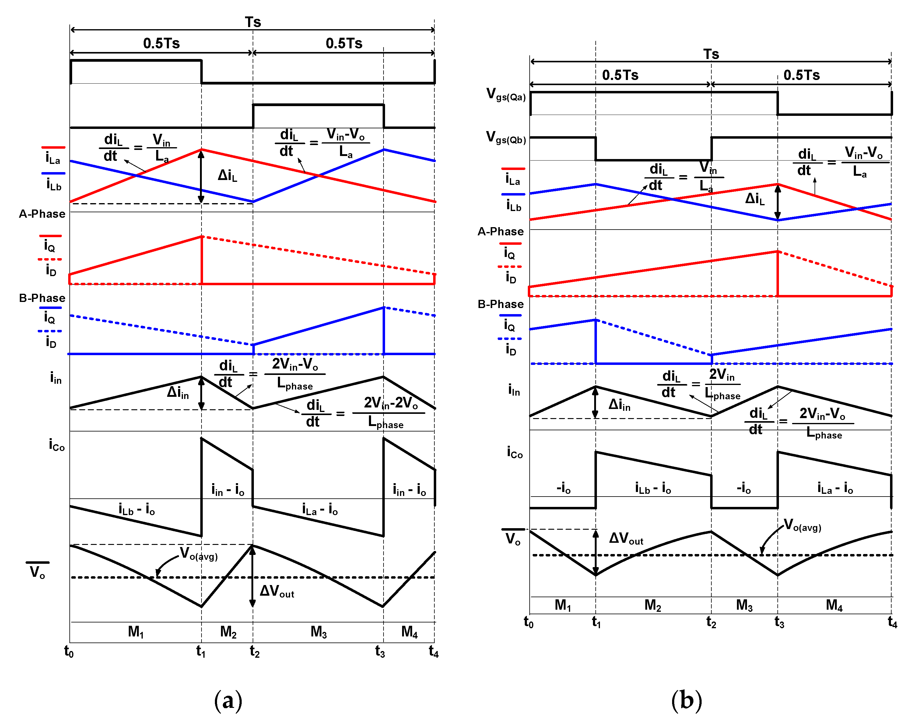
- all parasitic components except for those specified in Figure 3a are ignored;
- (2)
- the output capacitor (CO) is large enough to be considered as a constant output voltage (VO);
- (3)
- the inductances of every inductor are equal, and each average inductor current is well controlled and balanced;
- (4)
- Only two modes among four modes in one switching cycle are explained and analyzed since the two modes are symmetric with the other operational modes.
2.1.1. Operation of Interleaved Boost Converter during D ≤ 0.5
2.1.2. Operation of Interleaved Boost Converter during D > 0.5
2.2. Three-Level Boost Converter
- (1)
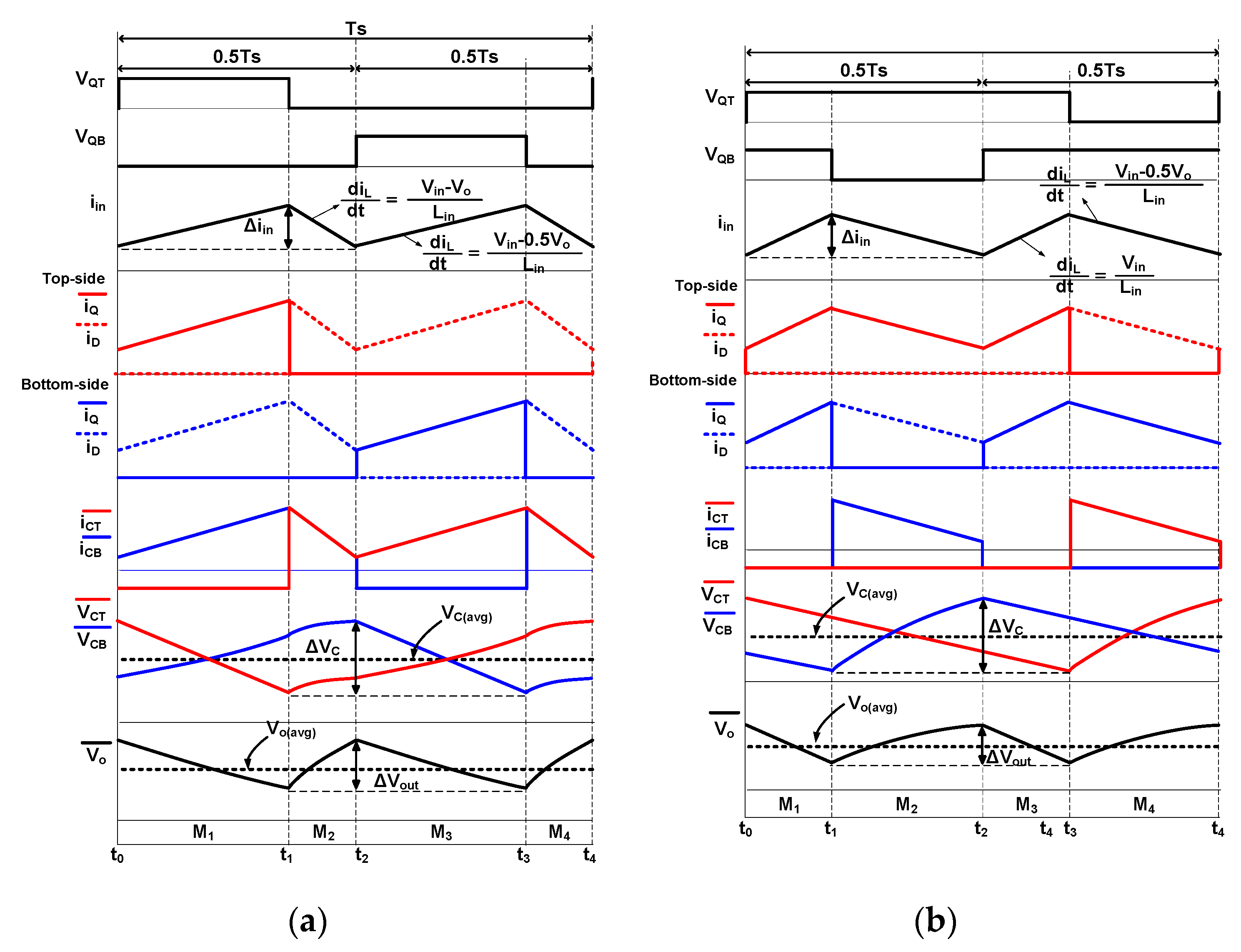
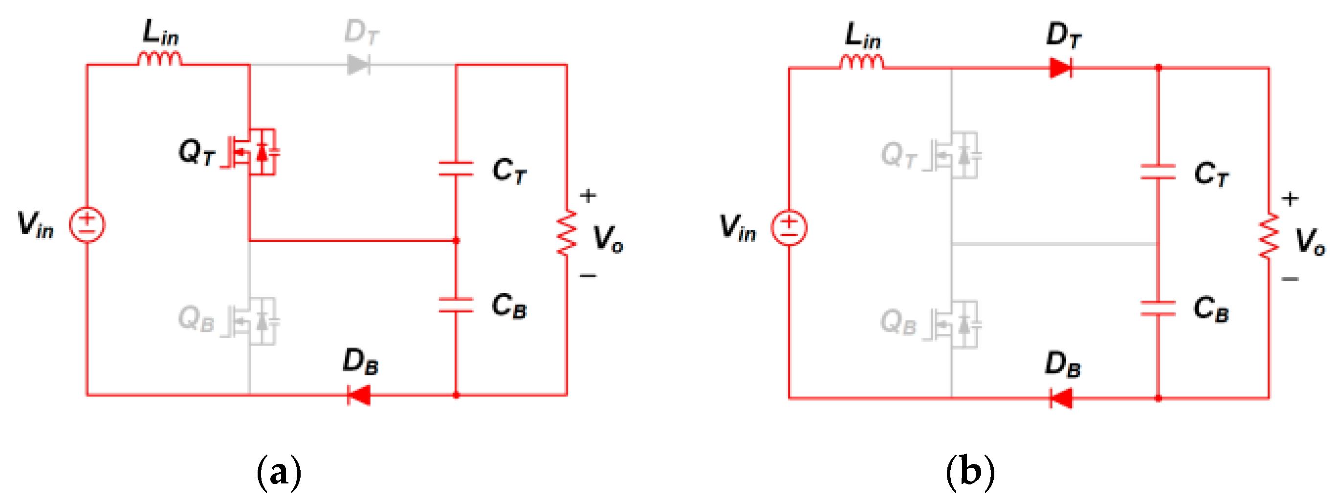
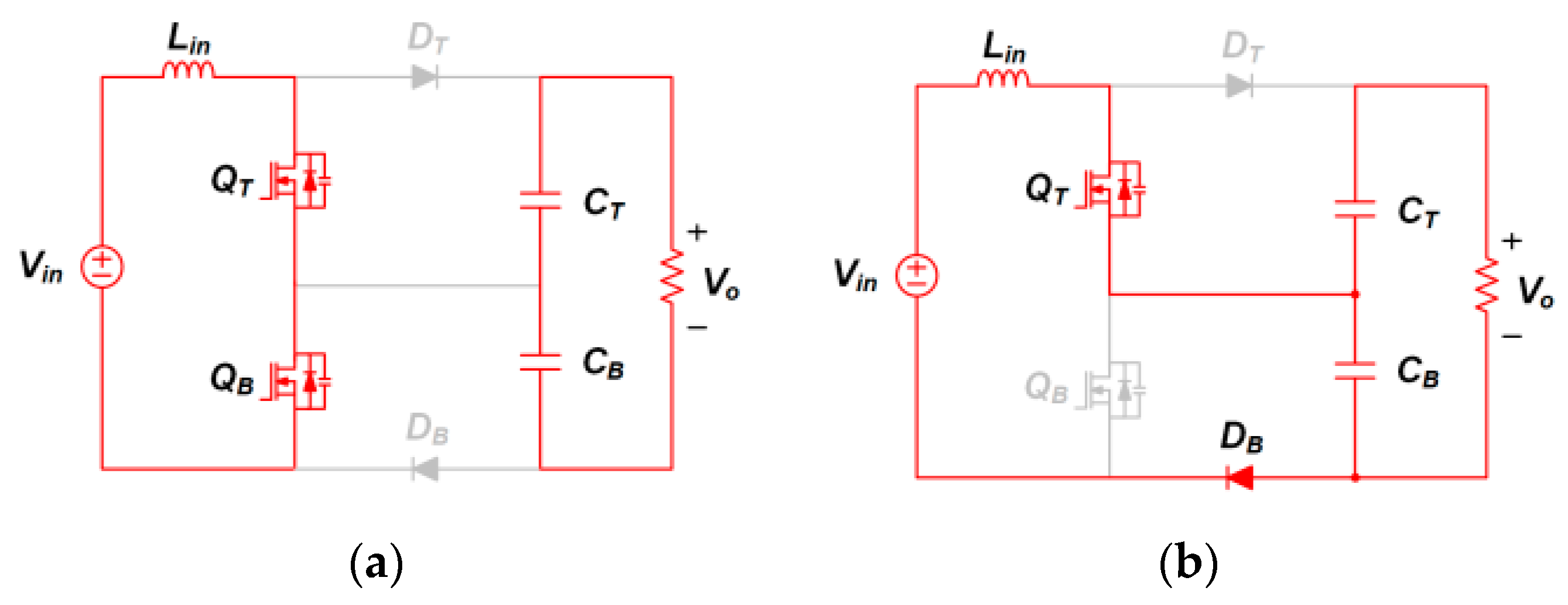
- all parasitic components except for those specified in Figure 3b are ignored;
- (2)
- the duty-ratio of QT (D1) is the same as the duty-ratio of QB (D2);
- (3)
- all output capacitance of capacitors (CT, CB) are equal, and the voltages of capacitors (VCT, VCB) are well balanced and the same as 0.5VO;
- (4)
- only two modes among four modes in one switching cycle are explained and analyzed since the two modes are symmetric with the other operational modes.
2.2.1. Operation of Three-Level Boost Converter during D ≤ 0.5
2.2.2. Operation of Three-Level Boost Converter during D > 0.5
3. Analysis and Design Consideration
3.1. DC Conversion Ratio of Interleaved and 3-Level Boost Converters
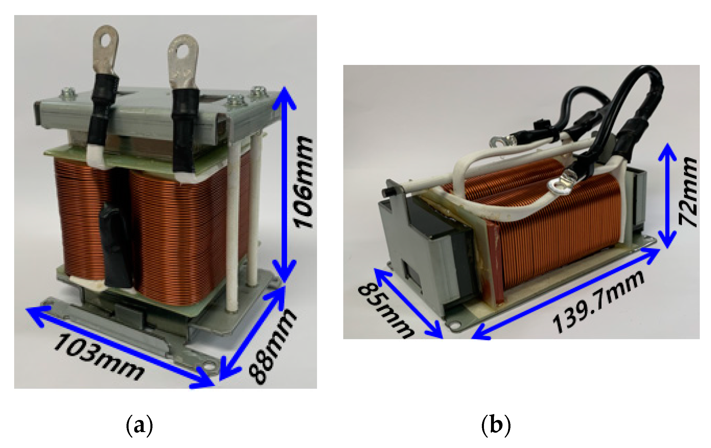
3.2. Boost Inductor Design Consideration
3.3. Output Capacitor Design Consideration
3.4. Voltage and Current Stresses on Switches and Diode
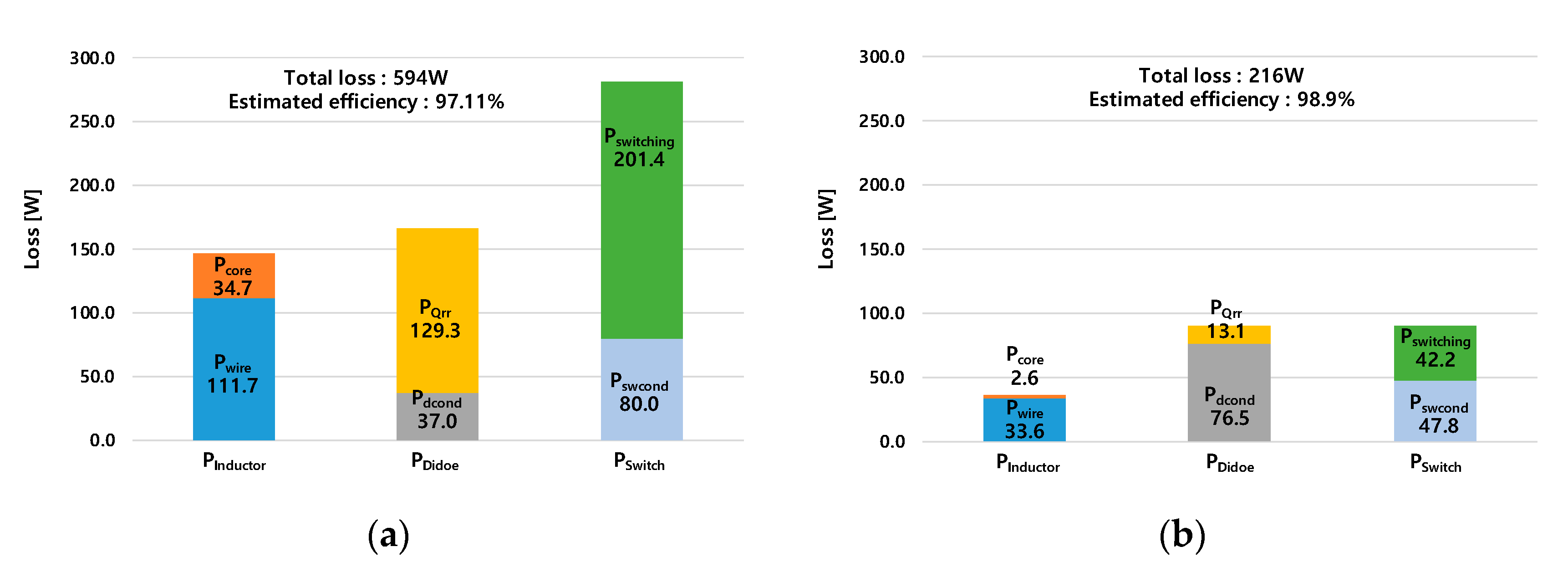
3.5. Loss Comparison between Interleaved and 3-Level Boost Converters
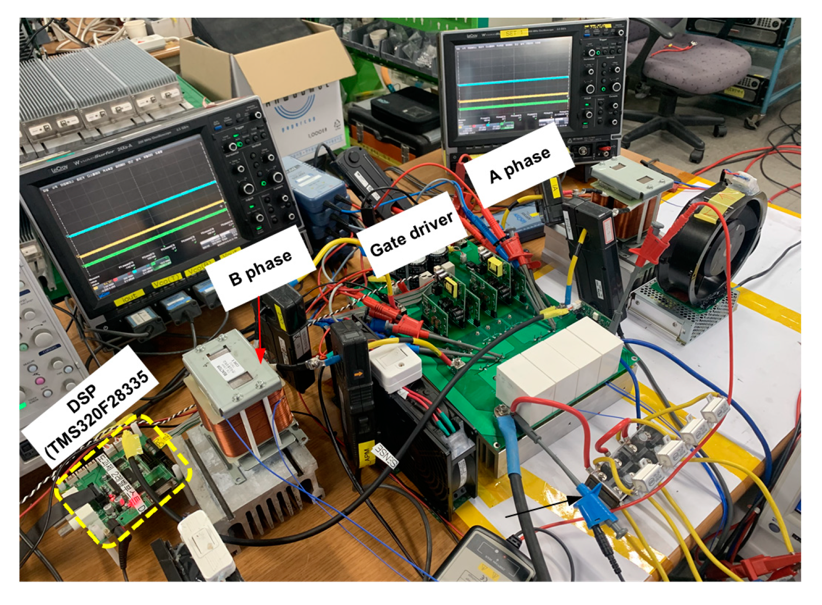
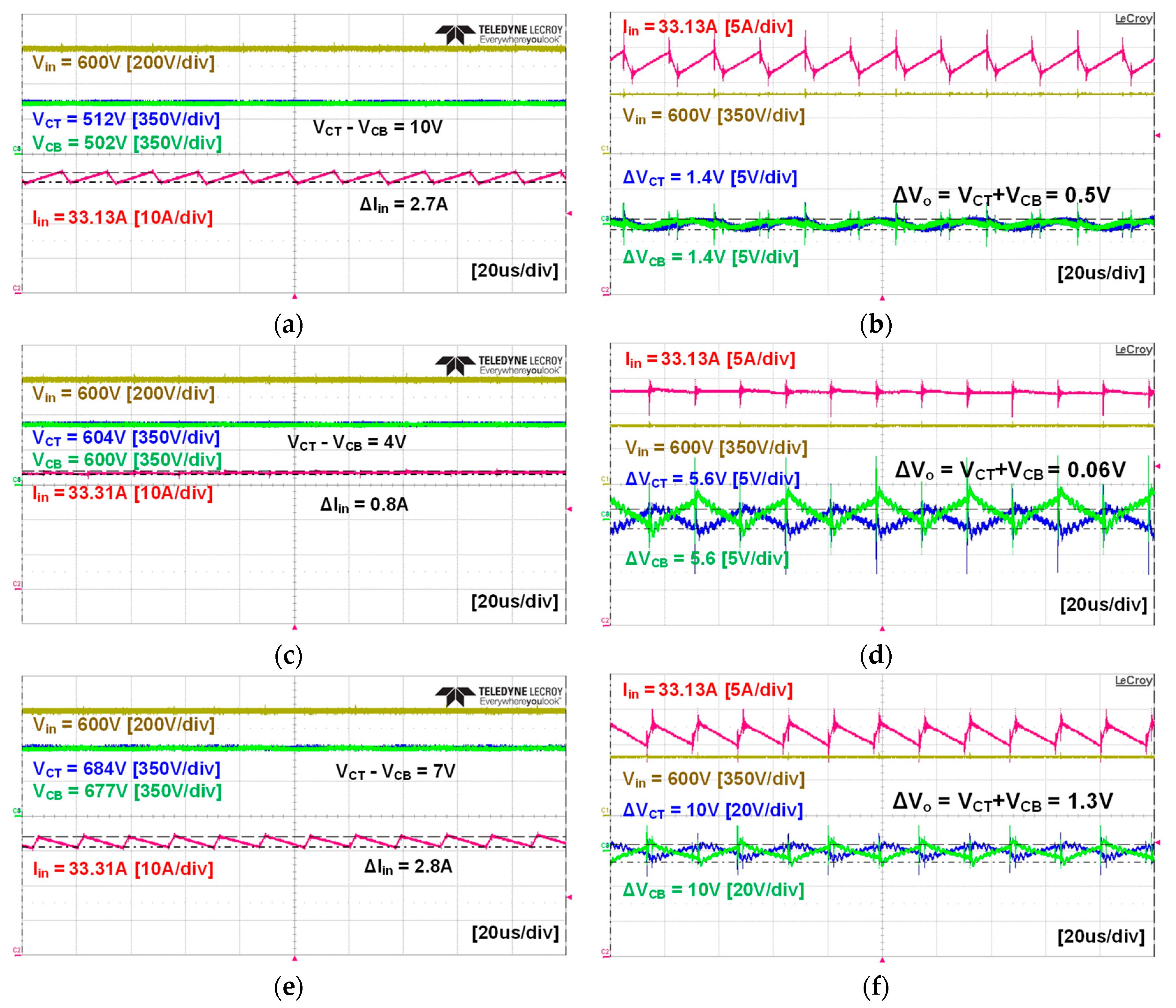
4. Experimental Results
5. Conclusions
Author Contributions
Funding
Conflicts of Interest
References
- Coradia iLint Hydrogen Train Receives Approval for Commercial Operation in German Railway Networks. Available online: https://www.alstom.com/press-releases-news/2018/7/coradia-ilint-hydrogen-train-recei-ves-approval-for-commercial-operation-in-german-railway-networks (accessed on 6 August 2019).
- Lim, S.-M.; Sung, S.-W.; Lee, Y.-K.; Kim, J.W. Technical Trends of Hydrogen Fuel Cell Railway Rolling Stock; The Korean Society For Railway: Jeju, Korea, 2018; pp. 314–317. [Google Scholar]
- Meleshin, V.I.; Zhiklenkov, D.V.; Ganshin, A.A. Efficient three-level boost converter for various applications. In Proceedings of the 15th International Power Electronics and Motion Control Conference EPE-PEMC 2012 ECCE Europe, Novi Sad, Serbia, 4–6 September 2012. [Google Scholar]
- Yaramasu, V.; Wu, B. Three-Level Boost Converter based Medium Voltage Megawatt PMSG Wind Energy Conversion Systems. In Proceedings of the 2011 IEEE Energy Conversion Congress and Exposition, Phoenix, AZ, USA, 17–22 September 2011; pp. 561–567. [Google Scholar]
- Kim, M.K.; Woo, D.G.; Lee, B.K.; Kim, N.J.; Kim, J.S. Loss Analysis of Power Conversion Equipment for Efficiency Improvement. Trans. Korean Inst. Power Electron. 2014, 19, 80–90. [Google Scholar] [CrossRef] [Green Version]
- Swamy, H.M.M.; Guruswamy, K.P.; Singh, S.P. Design, Modeling and Analysis of Two Level Interleaved Boost Converter. In Proceedings of the 2013 International Conference on Machine Intelligence Research and Advancement, Katra, India, 21–23 December 2013; pp. 509–514. [Google Scholar]
- High Flux Material Curves. Available online: https://www.mag-inc.com/Products/Powder-Cores/High-Flux-Cores/High-Flux-Material-Curves (accessed on 10 October 2019).
- Reddy, M.S.; Kalyani, C.; Uthra, M.; Elangovan, D. A Small Signal Analysis of DC-DC Boost Converter. Indian J. Sci. Technol. 2015, 8, 1–6. [Google Scholar] [CrossRef]
- Idoia, L.Z. Current Control Design and Implementation for a 2.4 kW Boost Converter for Fuel Cells; Grado en Ingeniería en Tecnologías Industriales: Pamplona, Spain, March 2017. [Google Scholar]
- Nouri, A.; Salhi, I.; Elwarraki, E.; el Beid, S.; Essounbouli, N. DSP-based implementation of a self-tuning fuzzy controller for three-level boost converter. Electr. Power Syst. Res. 2017, 146, 286–297. [Google Scholar] [CrossRef]
- Khaldi, H.S.; Ammari, A.C. Fractional-order control of three level boost DC/DC converter used in hybrid energy storage system for electric vehicles. In Proceedings of the 2015 6th International Renewable Energy Congress (IREC), Sousse, Tunisia, 21 May 2015. [Google Scholar]
- Chen, H.-C.; Lin, W.-J. MPPT and Voltage Balancing Control With Sensing Only Inductor Current for Photovoltaic-Fed, Three-Level, Boost-Type Converters. IEEE Trans. Power Electron. 2014, 29, 29–35. [Google Scholar] [CrossRef]
- Yadav, A.; Awasthi, A.; Karthikeyan, V.; Singh, A.K.; Das, V.; Karuppanan, P. Small SIGNAL modeling and stability analysis of N-phase interleaved boost converter. In Proceedings of the 2016 IEEE Uttar Pradesh Section International Conference on Electrical, Computer and Electronics Engineering (UPCON), Varanasi, India, 9–11 December 2016; pp. 585–590. [Google Scholar]
- Choudhury, S. Designing a TMS320F280x Based Digitally Controlled DC-DC Switching Power Supply; Application Report SPRAAB3–July 2005; Texas Instruments: Dallas, TX, USA, 2005. [Google Scholar]











| Parameters | Value |
|---|---|
| Output power (PO) | 20 kW |
| Input voltage (Vin) | 600 V |
| Output voltage (VO) | 1200 Vnorm (1008–1360 V) |
| Output voltage ripple (ΔVO) | 10.08 V (1% of minimum output voltage) |
| Input current ripple (ΔIin) | 3.3 A (10% of maximum input current) |
| Parameters | Interleaved Boost | 3-Level Boost |
|---|---|---|
| Required inductance (Lreq) | Lreq = La = Lb = 2.91 mH | 0.39 mH |
| Required AP (mm4) at BM = 0.5 T, Ku = 0.3, J = 6 A/mm2 | La + Lb = 1797,014 m4 | L = 481,385 mm4 |
| Core | La: High flux 58737, 2EA (series connected) Lb: High flux 58737, 2EA (series connected) | High flux 58737 |
| Core permeability | 60 μ | 60 μ |
| AL,min value of core | 187.68 nH/T2 | 187.68 nH/T2 |
| Turns for each core/J (A/mm2) | 112/6 | 66/6 |
| Real min inductance (Lmin) without DC-bias | Lmin = La = Lb = 2.35 mH × 2 | Lmin = 0.82 mH |
| Real min inductance (Lmin,dc) with DC-bias | Lmin,dc = La = Lb = 1.45 mH × 2 at 101 AT/cm | Lmin,dc = 0.39 mH at 119 AT/cm |
| Total number of inductors or cores | 4 | 1 |
| Parameters | Interleaved Boost | 3-Level Boost |
|---|---|---|
| Required capacitance (Creq) | Creq = CO = 15.92 μF | Creq = CT = CB = 8.5 μF |
| Maximum voltage stress | 1360 V | 680 V |
| Capacitor/capacitance | C4AQSBW5220A3NJ × 4EA/ 22 μF × 4 | CT: C4AQSBW5220A3NJ × 2EA/22 μF × 2 CB: C4AQSBW5220A3NJ × 2EA/22 μF × 2 |
| Number of Capacitor | 4 | 4 |
| Parameters | Interleaved Boost | 3-Level Boost | |
|---|---|---|---|
| Switch | Max voltage stress | 1360 V | 680 V |
| Max current | 23.86 A | 34.86 A | |
| RMS current | 12.47 A | 21.3 A | |
| Required margin (Voltage/Max/ RMS current) | 50%/100%/100% | 50%/100%/100% | |
| Part number (voltage/drain current) | IXBH25N250 (2500 V/25A at TC = 90 °C) | C3M0032120D (1700 V/48A at TC = 100 °C) | |
| Diode | Max voltage stress | 1360 V | 680 V |
| Max current | 23.86 A | 34.86 A | |
| Average current | 9.5 A | 20 A | |
| Required margin (Voltage/Max/ Average current) | 50%/100%/100% | 50%/100%/100% | |
| Part number (voltage/average current/VF) | IXBH25N250 (reverse diode), (2500 V/9.5 A/1.4 V at Tj = 135 °C) | C3M0032120D (reverse diode), (1700 V/48 A/1.4 Vat Tj = 135 °C) | |
| Parameters | Interleaved Boost | 3-Level Boost |
|---|---|---|
| Inductor (at 100% load) | 2.9 mH per phase (1.45 mH × 2EA, 2-series connection per phase) Core: Nano crystalline | 0.39 mH Core: Ferrite |
| Capacitor | CO = 15.92 μF (22 μF × 4EA = 88 μF, (4-parallel connection) | CT = CT = 8.5 μF (CT, CB: 22 μF × 2EA = 44 μF, 2-parallel connection per capacitor) |
| Switch | IXBH25N250 × 8EA (4-parallel connection per phase) | C3M0032120D× 4EA (2-parallel connection per switch) |
| Diode | IXBH25N250 × 4EA (2-parallel connection per phase) | C3M0032120D× × 8EA, (4-parallel connection per diode) |
| Parameters | Interleaved Boost | 3-Level Boost | |
|---|---|---|---|
| Inductor (per core) | Rwire | 100 mΩ | 30 mΩ |
| ΔB | 0.2 T | 0.018 T | |
| Switch | VCE or Rds_on | 2.4 V | 43 mΩ |
| Coss | 75 pF | 129 pF | |
| Ton | 650 ns | 22 ns | |
| Toff | 500 ns | 19 ns | |
| VF (Body diode) | 2.4 V | 2.6 V | |
| Qrr (Body diode) | 2.97 μC | 80 nC | |
© 2020 by the authors. Licensee MDPI, Basel, Switzerland. This article is an open access article distributed under the terms and conditions of the Creative Commons Attribution (CC BY) license (http://creativecommons.org/licenses/by/4.0/).
Share and Cite
Youn, H.-S.; Yun, D.-H.; Lee, W.-S.; Lee, I.-O. Study on Boost Converters with High Power-Density for Hydrogen-Fuel-Cell Hybrid Railway System. Electronics 2020, 9, 771. https://doi.org/10.3390/electronics9050771
Youn H-S, Yun D-H, Lee W-S, Lee I-O. Study on Boost Converters with High Power-Density for Hydrogen-Fuel-Cell Hybrid Railway System. Electronics. 2020; 9(5):771. https://doi.org/10.3390/electronics9050771
Chicago/Turabian StyleYoun, Han-Shin, Duk-Hyeon Yun, Woo-Seok Lee, and Il-Oun Lee. 2020. "Study on Boost Converters with High Power-Density for Hydrogen-Fuel-Cell Hybrid Railway System" Electronics 9, no. 5: 771. https://doi.org/10.3390/electronics9050771
APA StyleYoun, H.-S., Yun, D.-H., Lee, W.-S., & Lee, I.-O. (2020). Study on Boost Converters with High Power-Density for Hydrogen-Fuel-Cell Hybrid Railway System. Electronics, 9(5), 771. https://doi.org/10.3390/electronics9050771


