1. Introduction
A power grid is a complex system where electric power suppliers and users are connected through transmission and distribution networks across a large area. The vulnerability and potential problems of the power grid have exposed the challenges of energy transmission and distribution. There are various reasons why the grid may continue to undergo failures. For instance, two features of the grid, (1) being permanently energized and (2) permitting discretionary access to energy at any time and of any amount, make the grid depend on an accurate load forecasting and delicate balance. They also expose the grid to uncontrolled delivery and failures. In addition to that, electricity demand has sharply increased in recent years, and that requires larger amounts of power on a line and increasing grid capacity. Besides, there is an increasing interest in integrating renewable resources into the power grid to decrease greenhouse gas emissions [
1,
2,
3]. There is a need to consider a global transition to green energy, not only to transform the global energy sector from fossil-based to zero-carbon, but also for positive social implications, such as economic and environmental sustainability [
4,
5,
6,
7,
8,
9]. One of the challenges of the energy transition is to integrate renewable energy sources with the power grid system, but that also demands additional forecasting and management complexity [
3,
10]. Therefore, it is clear that the present grid has to overcome some challenges in integrating alternative energy sources.
As a possible solution to some of those challenges, several researchers and industries have proposed the concept of a digital grid (DG) [
11,
12,
13,
14,
15,
16] as an approach to meet the requirements of the next-generation power grid. In such a paradigm, the grid transmits energy as the Internet transmits data. In the DG, elements of the grid (e.g., sources, distributors, buses, and loads) communicate and are assigned unique identifiers, or Internet Protocol (IP) addresses. The adopted communication and assigned identity enable them to play active roles in estimating and configuring the path that electrical energy follows from the sources to the loads, prior to the actual transmission.
A large area DG may be segmented into multiple autonomous cells, and that makes it possible to interchange power among the smaller grids or grid segments. This approach enables the grid to perform a finer distribution of energy such that defined amounts of energy may be routed through specific grid segments or microgrids [
17,
18]. Microgrids are becoming a functional and building block of the next-generation power grids. The versatility of microgrids to host multiple energy resources, configure one or multiple paths for redundancy, and the incorporation of data communications to monitor and control the configuration of the distribution legs make them attractive [
19,
20].
The application of the DG concept on a microgrid is what we call a digital microgrid (DMG). This grid is able to transmit energy in a store-and-forward mechanism that follows the execution of a request-grant protocol by loads and sources. In such a protocol, loads issue requests for energy through a parallel data network, and the source grants the energy, if there is enough of it available. Furthermore, the transmission of energy from node to node of a DMG enables the management of energy distribution in a robust manner. The DMG may use a power router to transfer energy from one link (or smaller grid) to another [
13,
21,
22,
23,
24,
25,
26,
27]. Such a power router has multiple inputs and outputs, or legs. They can interconnect multiple segments and form an extended microgrid. The end topology of the microgrid would be a meshed network [
12]. Xu et al. [
13] proposed a power router that is comprised of a power path, which delivers energy to loads, and a data path, which transmits the information to monitor the demand and supply of energy. The inputs and outputs of the power router handle data and power. Matsuura et al. proposed [
23] a three leg digital grid router to connect alternating current (AC) lines of each leg asynchronously by using multiple bi-directional AC/DC inverters. Moreover, Takahashi et al. presented an AC power circuit switching system and a DC power packet dispatching system; in both systems, the power routers are implemented and used to transmit both energy and information [
24,
25,
26]. In addition, Girbau-Llistuella et al. [
27] proposed an intelligent power router that controls the power flow by means of power converters.
Different from those approaches, Jiang et al. proposed the design of an energy packet switch that plays the role of a DMG node that handles energy in a discrete fashion [
21,
22]. An energy packet switch (EPS) uses a store-and-forward flow control to transfer energy from one segment to another. The operation of the EPS is based on storing the received energy and forwarding it to the loads or other EPSs. It should be noted that an EPS is not an energy storing device, but a forwarding one, and to perform this function, the EPS may temporarily store the passing energy. The EPS is built with energy storage units, such as supercapacitors, where each supercapacitor stores the amount of energy to be transferred to the receiving node. Therefore, the path that interconnects a load to the energy source is comprised one or more EPSs, and it can be represented as a chain of interconnected supercapacitors. This path requires having sufficient supercapacitors to accommodate the transfer of a large number of flows and large amounts of energy. However, each energy transfer may suffer from energy loss, which is a function of the voltages and capacitance used in each node. Therefore, a transfer path must: (a) consider the amount of required capacitance through the path to avoid overwhelming a node and to allow a large number of flows to use portions of the path and (b) be efficient and accrue for a minimum energy loss.
Therefore, the adoption of EPSs in a DMG raises the following question: Can we route energy from sources to loads in a DMG through optimal paths that either minimize losses of energy or that require a small capacitance to transfer energy requested by the loads? We answer this question by proposing an energy routing scheme that finds the paths from sources to loads that incur a small capacitance at each node while considering the conditions for the transfer of energy that require the smallest energy losses. The scheme considers paths comprised of EPSs and their limited number of supercapacitors to configure the needed capacitance to transfer energy.
We first present the design of an EPS and discuss how energy is distributed in the DMG through multiple EPSs. In addition, with the incorporation of EPSs in the DMG, we show that the energy loss on the energy-transmission path is independent of the number of intermediate nodes and find out the conditions that reduce energy losses as energy is transferred. By minimizing the energy loss in each transfer and the required capacitance, a DMG is leveraged to scale up the number of energy flows it can accommodate and power up more loads. We discuss the trade-offs for increasing efficiency and scaling up the DMG.
The contributions of this paper are: (1) the proposal of a routing scheme to find the transmission path of an energy flow between an energy source and a load that uses small capacitance, (2) a theoretical analysis of the conditions needed to minimize the energy loss associated with energy transfer through capacitances in a store-and-forward energy transfer mechanism, (3) a demonstration that the transfer of energy in a store-and-forward DMG only depends on the capacitance of the nodes exchanging energy, and (4) a demonstration that the proposed routing scheme can find a path with a small amount of capacitance by adjusting the pre- and post-transfer voltages.
The remainder of this paper is structured as follows.
Section 2 briefly introduces the DMG and the design of an EPS.
Section 3 introduces and analyzes the conditions required to minimize the energy loss when energy is transmitted in the DMG through multiple EPSs.
Section 3 introduces our routing algorithm to select a transmission path that incurs the smallest path capacitance while keeping energy losses small.
Section 4 presents the experimental results of a DMG testbed with two EPSs where we experimentally validate our theoretical analysis.
Section 5 concludes our paper.
2. Digital Microgrid with Energy Packet Switch
The main goal of a DMG is to supply discrete and finite amounts of energy as a digital grid. In order to control the energy delivered in discrete amounts to a load on a network-controlled power grid as a more robust approach to a digital grid, a novel energy packet switch (EPS) was proposed in [
21]. The proposed EPS was able to aggregate energy from multiple sources without affecting the stability of the power loop and, therefore, the complete grid.
Figure 1 shows an example application of EPS where the switch is used to integrate the energy provided by
S different energy sources and supply energy to up to
D different loads. The switch is based on multiple units of shared energy storage, where one or multiple sources that are connected to the inputs of the switch may supply energy to one or multiple storage units. In the EPS, a shared storage is implemented with a supercapacitor bank, and therefore, the EPS works with direct current (DC).
Figure 2 shows the diagram of a
(two inputs, two outputs) EPS. In this EPS, there are
M supercapacitors where energy can be stored and retrieved.
In our design, EPSs can be interconnected with other EPSs to increase the network size or interfacing with many sources or loads. In a DMG network, an EPS plays the role of a load when it receives energy from other EPSs or sources and the role of a source when it transfers energy to other EPSs or loads. As shown in
Figure 2, solid-state relays (SSRs) perform the function of switching elements in the EPS. These SSRs configure which supercapacitor gets connected to either an input or an output of the EPS. The EPS uses a controller that sets the state of the switching elements as closed (connected) or open (disconnected), according to the amount of requested energy and the amount of available energy. The switch elements interconnect one input to one or multiple supercapacitors for charging and one or multiple supercapacitors to one output for transferring energy to the load.
3. Efficiency Analysis in the DMG
In the DMG, the energy is transmitted from the energy sources to the loads through multiple intermediate EPSs. Here, we present a mechanism to minimize the energy loss when the energy is transmitted on a path between the source and the load. In addition, we present an algorithm for minimizing the amount of required capacitance when energy is granted from the source to the demanding load. There are two features of the DMG that allow us to center the analysis of energy loss into the transmission path: (1) the sources, EPSs, and loads execute the request-grant protocol before energy is transferred; and (2) only the node closest to the source receives energy directly from the source, and similarly, only the node closest to the load supplies energy directly to the load.
3.1. Energy Loss Model
Consider an energy flow path with
N intermediate nodes where the EPSs are implemented, as shown in
Figure 3a, and energy is transferred from the source to the load. The power source and load are connected to Node 1 and node
N, respectively. In the remainder of the paper, we use the voltage levels to indicate the amount of energy in a given capacitance. We model the transfer of energy from a charged capacitance to another with less or no energy after being interconnected so a balance of charges takes place. This process occurs sequentially in a per-link basis in what we call a store-and-forward energy transmission.
To calculate the energy loss along this path, we consider the following:
There are
N intermediate nodes along the path. Link
i connects nodes
i and
, and the energy transfer process
i (i.e., the flow of energy from node
i to
, shown in
Figure 3b) occurs between those nodes.
Each node is an EPS, and the number of available capacitorsin the ith node is , while the capacitance is dedicated to a particular energy transfer; as the set of dedicated capacitors for that transfer, is .
Each supercapacitor in the microgrid has the same capacitance C.
The voltage of the source, , is constant (or independent of the amount of energy transfer). The target voltage of the load is . This voltage is the one at which node N is to be charged.
The voltages of the supercapacitors in the ith node before an energy transfer and after an energy transfer are denoted as and , respectively.
Considering that the transfer of energy from node i to node occurs before and at different times than a transfer from node to node , then the voltage of node i after the transfer is equal to the voltage of node before it transfers energy to the following node, or . Here, we refer to as the transfer voltage difference, V, in the remainder of this paper.
To find out the minimum energy loss, the objective function is defined as the minimum energy path loss, or:
where
is the energy loss on link
i. The loss at a link comes from a capacitor-to-capacitor energy transfer, where one capacitor is charged and connected to another capacitor, with a smaller charge. Once connected, the charges balance among the two capacitors so that the two capacitors are set at the same voltage (as a function of the charge). However, the capacitor-to-capacitor energy transfer is subject to energy loss [
28]. The energy transfer is shown by
Figure 3b. Here, once
is charged, the switch connects it to
to transfer energy. Depending on their capacitance,
and
share charges and end up holding the same voltage. In Reference [
28], it was proven that the energy loss when energy is transferred between two parallel capacitors does not depend on the resistance of the resistor,
R.
For energy transfer process at node
i, we have the following constraint function:
where Equation (
2) is the electric charge conservation equation and Equation (
3) represents the energy loss on link
i.
By using Equations (
2) and (
3) in the path with
N nodes, we obtain the total energy loss,
, as:
This loss includes losses from Node 1 to node
N. Note that
,
, the capacitance of the last node, that capacitance
is constant, and the path energy loss only depends on Node 1, and this loss is independent of the number of nodes in the path. From Equation (
4), we observe that the smaller
(or the larger
V), the smaller the energy loss in an energy transfer. Therefore, the voltage constraint can be written as:
It is worth noting that
, as Equation (
4) indicates, is independent of link resistance [
28]. The energy loss of two charged capacitors has been extensively discussed, and the results show that the total energy loss is not a function of the resistance [
28]. Therefore, this loss depends only on the voltages and capacitance of the capacitors transferring energy. The resistance only influences the speed at which energy is transferred. However, in a traditional power grid system, the total energy loss can be significant on links with resistance.
3.2. Conditions for Minimizing Energy Loss at Energy Transfers
Equation (
4) shows the path loss when energy is transmitted in the DMG from a source to a load. To illustrate the meaning of this equation, we used the IEEE 14 test bus [
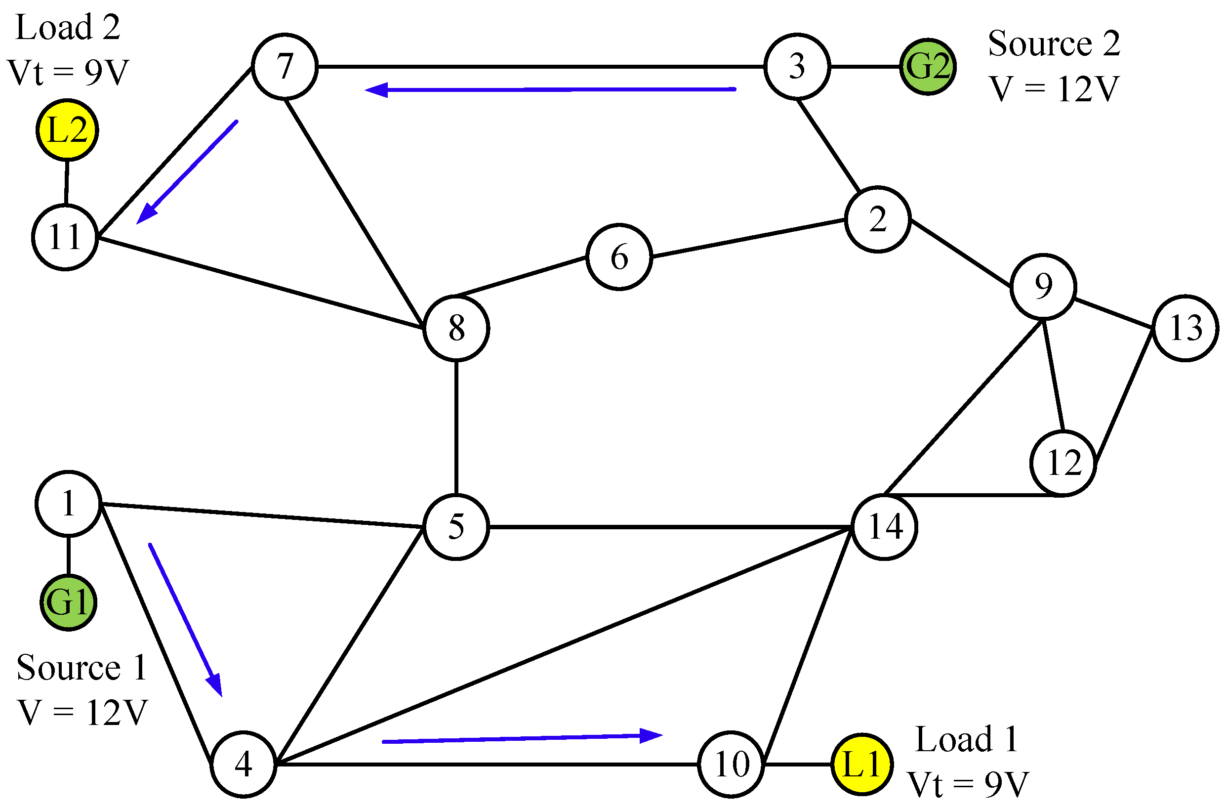
29] to estimate how much energy was lost in different scenarios. IEEE 14 test bus represents a simple approximation of the American Electric Power system as of February 1962. It contains 14 buses, and multiple sources and loads can be integrated into the test bus. As shown in
Figure 4, the DMG has two energy sources (they are connected to Nodes 1 and 3) and two loads (they are connected to Nodes 10 and 11). The target voltage of each load is 9 V, which means the supercapacitors of Nodes 10 and 11 should be both charged to 9 V. The voltage of each source is 12 V so that the supercapacitors in Nodes 1 and 3 can be charged to 12 V before any energy transfer. The blue arrows in the figure show possible energy flows from a source to a load.
The transfer paths 1-4-10 and 3-7-11 were selected to supply energy to loads L1 and L2, respectively; they had the same number of hops. Let us consider 1-4-7 as an example to show the energy loss of a path when energy is transferred through it. As discussed above, the path energy loss depends on only
, the voltage of Node 1 after energy is transmitted from Node 1 to its neighbor Node 4 in this path. In addition, according to (
5),
is the voltage between 9 and 12 V. Let us consider different values for
and calculate
for each case.
Table 1 shows the voltages of each node, the required path capacitance, and the energy loss of three different cases where
was set to different values. In the first case, assume that
= 10.5 V, the initial voltage of Node 10 is 0 V,
= 0 V, and its capacitance is
C. In this case,
= 10.5 V and
= 9 V because the target voltage of Node 10 is 9 V. In this case,
= 10.5 V, and the energy loss
of this case is 60.75
C J. Cases 2 and 3 show the examples when
is 10 and 9.5 V, respectively. As shown in the table, when
= 10 V (
V
= 2 V), the required path capacitance is 14.5
C and
C J, and when
= 9.5 V (
V
= 2.5 V), the path capacitance is 22.6
C and
C J.
Figure 5 shows the relationship between energy loss at the link and path levels and
. In the figure, the red and blue lines show the energy loss on Link 1 (transfer from Node 1 to Node 4) and Link 2 (transfer from Nodes 4 to 10), respectively. The black line in the figure shows that when
decreases,
also decreases. In other words, when
V
increases, the energy loss decreases. It is then clear that it is desirable to have the largest
V in the first node, as indicated by (
4).
Note that each of these cases requires a different capacitance at the EPS and, in turn, the path. Note that when 9.5 V, the required path capacitance is the largest of the three scenarios, or 22.6C. This large capacitance is required because V is the largest at this node, but then V for Node 4 is very small, 0.5 V. Therefore, Node 4 will be required to use a large capacitance, 18C, as shown in the table. When 10.5 V, the required capacitance is 13C, which is the smallest required path capacitance of the three cases. This small path capacitance is the result of using the largest V, or the same V for each node. Note that we assume that each EPS has enough supercapacitors to satisfy the required capacitance in this section. However, if a node cannot provide enough capacitance, we have to select another path that has enough capacitance, or else a different V at each node on the same path. However, the latter option will increase the path energy loss. A third option is to use multiple paths, but that is out of the scope of this paper.
3.3. Minimize the Required Path Capacitance
As discussed above, it is necessary to minimize the required path capacitance when transferring energy from the source to the load to accommodate a large number of energy transfers, or flow. According to (
2):
The required path capacitance can be represented as:
where
is the required path capacitance and
and
are both constant. Therefore, the objective function may be defined as:
Based on the assumption presented in
Section 3.1, where
, the solution of the optimization problem is:
where (
9) is obtained by applying the property that the harmonic average of a set of positive numbers is smaller than or equal to the arithmetic mean of these numbers [
30]. Therefore, the required amount of capacitance can be minimized as:
This solution applies when
V is the same for each node in the path, which means that:
3.4. Finding The Smallest Path Capacity in an EPS Network
As (
10) indicates, the path requires the smallest path capacitance to be the path with the smallest number of hops between the source and the load; the shortest path. Therefore, we need to find the shortest path that has enough capacitance to transfer the requested amount of energy by a load.
We therefore propose a routing algorithm for finding the smallest capacitance path to transfer energy from a source to a load. We consider here that each load has pre-selected the source that supplies its energy.
Figure 6 shows the flowchart of the path-selection algorithm. The algorithm first considers the shortest path for each load. If the path has enough capacitance to satisfy that required,
according to the selected voltage,
, the path is selected. Else, the algorithm considers two options to fulfill the requirement: (1) On the shortest path, it considers a larger
V at the bottleneck node. However, as
V decreases for the nodes that are closer to the source, so is the required path capacitance. The required path capacitance is represented by
p. If
V at the bottleneck node is too large, the required node capacitance of the nodes previous to the bottleneck may be infinity,
INF, as shown in the figure. Then, this path cannot be used to transfer energy. (2) Find a larger path (i.e., a path with a larger number of hops) and compute again the required capacitance, but by considering again equal
V at each node, or the smallest energy path loss. This process repeats in the immediate larger paths until a path that satisfies the required path capacitance,
q, is found. Furthermore, this process may help to keep the
q smaller than that of the previously selected path. Similarly, if some nodes on the path cannot provide sufficient capacitance,
q also may be infinity,
INF, shown in the figure. By selecting the path with the smallest available capacitance, the DMG can accommodate the largest number of energy flows.
In order to analyze the complexity of this path-selection algorithm, we modeled the network as a graph
that also considers
g sources and
l loads as especial nodes, where
is the number of edges in the network. In addition,
u, where
, is a node in the set of nodes
V in the network, and edge
, where
in the set of edges
E. To find the path with the minimum number of hops in the algorithm, the Dijkstra algorithm [
31] can be applied. The time complexity of this algorithm is
. Considering that there may multiple sources and loads in the network, the total time complexity of the algorithm to find the path with the minimum number of hops from one source to one load becomes
. For the other parts of the algorithm, such as checking if the least-hop path is available or calculating the required capacitance, one iteration along the selected path is required, so that the complexity is
, less than
. Therefore, the total complexity of this algorithm is
.
3.5. Example of Routing to Find a Small Path Capacitance
Here, we study a DMG with nodes as shown in
Figure 7 to show how the proposed routing algorithm works. In this network, there are two demanding loads as before; connected to Nodes 10 and 11. Path 1: 1-4-10 is used to transfer energy for L1, and Path 2: 3-7-11 is used to transfer energy for L2, as the blue arrows show in the figure. The required path capacitance for each path is 13
C F. Now, let us focus on Path 2 and consider a new load, L3, which is connected to Node 8, which also demands energy. The shortest path for L3 is 3-7-8. However, now, Link 3-7 and Node 7 are shared by two paths. According to the path selection algorithm, Path 3-7-8 can be selected to transmit energy from Node 3 to Node 8 if both Node 3 and Node 7 can each provide 6
C. The required capacitance and voltages for each node are shown in
Table 2.
On the other hand, if Node 7 has an available capacitance smaller than 6
C F, then there are two path options: (1) Keep considering the shortest path, Path 3-7-8 shown by the red arrows in the figure, but use more capacitance at the source node (with a smaller
V) and, therefore, a larger path capacitance, to relax the capacitance required in the intermediate nodes. (2) Find a larger path, such as Path 3-2-6-8, as shown by the green arrows in
Figure 7, that may have sufficient capacitance in each node.
Table 3 and
Table 4 show the capacitances on these two path options.
Table 3 shows that Node 7 cannot provide 6
C F, but 4
C F. In this case, then the required path capacitance is 17
C F, which is larger than in the previous case.
Table 4 shows the capacitance of the larger path, Path 3-2-6-8, as 28
C.
We draw a graph of the relationship between the number of capacitorsat Node 7 vs. the path capacitance to provide an insight to this relationship. As shown by
Figure 8, the curve shows that when the capacitance of Node 7 is smaller than 6
C F, the required path capacitance increases. For example, when the capacitance of Node 7 decreases to 3
C, the required path capacitance is infinity. With this condition, Node 7 cannot be used to transfer the energy to Node 8. Point a in the graph indicates that when Node 7 provides 3.4
C F, by using (
7), the required path capacitance is 28
C F, which is equal to the path capacitance of
Table 4, but here, each node of the path can provide enough capacitance to transmit energy. Therefore, from the figure, we can conclude that when Node 7 has more than 3.4C F, Path 1 is optimal, as it requires smaller capacitance than Path 2. Otherwise, Path 2 is optimal.
3.6. Discussion of the Minimum Energy Loss and Minimum Path Capacitance
There are several claims in this work that unveil information about the features of a store-and-forward DMG. These features include advantages and requirements for the operation of such a microgrid. We list the features as follows:
Path length independence: As (
4) shows, the total energy loss in this DMG is path-independent; this loss depends on
, which is the voltage of the capacitors at Node 1 (the node that handles the energy from the source) after supplying energy to its neighbor, Node 2. In general, this is the voltage of the node where the energy source is connected. This property shows that sources do not need to be in the proximity of a demanding load and that the DMG can flexibly integrate resources located in different locations. There is a path capacitance that needs to be considered, however. This point is discussed below. At the same, this property also requires that voltage differences in the intermediate nodes of a path must be kept to a minimum to avoid violating the conditions to preserve this property for a DMG.
Energy loss dependency: As (
4) also shows, the total energy loss is the lowest when the voltage of the node closest to the source approaches the load target voltage (i.e., the voltage at which the load operates), or
V is the largest. Therefore, the energy loss when energy is transmitted from a source to a load can be minimized by setting
closer to
or having a large
V
. This property means that if there is a large difference between the voltage a source can provide and the target voltage, this difference must be the largest at the first node of a path. While in some cases, the existing path capacitance does not allow exercising this property, using alternative paths will come at the cost of energy loses. This loss is a direct result of using energy conservation when energy transfer takes place between two capacitances that have different energy levels. Therefore, the conservation of this property is determined by the amount of capacitance available in the source-load path. Furthermore, this property must be considered for a suitable EPS design, as such an EPS must have a configurable (adjustable) capacitance. An EPS is implemented with a large number of super-/hyper-capacitors, and this number and the capacity of each of them are defined by the required energy capacity and energy resolution, respectively.
Capacitance vs. energy loss: However, adjusting the voltage
to a smaller voltage requires a larger path capacitance in that node. In the DMG, with each node implemented as an EPS, the capacitance is limited by the number of supercapacitors in each EPS. Therefore, it is also important to find out how to select the most desired path under the constraint that the capacitance of a node is limited. As discussed in
Section 3.5, the required path capacitance depends on the selected path. The proposed routing algorithm in this paper can select paths with the minimum required amount of capacitance, and therefore, the DMG can accommodate a larger number of loads. The capacitance-energy loss trade-off also means that the source-load path must be carefully selected. For example, in an actual application of this concept, it may be the case that higher voltages than those used in the distribution loop may be considered. In such cases, voltage differentials may occur at every network node, but then, the minimum required capacitance must be satisfied, so the voltage differentials to achieve an efficient energy transfer. The proposed path selection algorithm addresses this balance.
Resistance independence: Our analysis shows that the capacitance-to-capacitance energy transfer is independent of the resistance of the interconnection. This is an interesting result and property because if energy transfers are performed between nodes without directly powering a load (e.g., during the energy transfer), energy losses are minimized. The explanation for this phenomenon is that charges continue to move in the capacitance-to-capacitance energy transfer, and any resistance in between may affect the transfer speed and not the dissipation as charges move at the speed set by the resistance. In a traditional power grid system, the total energy loss can be significant on links with resistance. Therefore, the proposed store-and-forward energy transfer mechanism is suitable for energy transmission when the path between the source and the load has some resistance whose energy expenditure is amplified by the circulation of large currents. This network takes advantage of having capacitance-to-capacitance sharing of charges. Moreover, such energy loss depends on the loads connected to the loop.
4. Experiments on a Scaled-Down DMG Testbed
We applied our proposed algorithm to a real scaled-down DMG and show the validity of it. We built our DMG testbed with two 2 × 2 EPSs, two energy sources and two loads.
Figure 9 shows the diagram of the testbed, and
Figure 10 shows a photograph of it. A user in the photograph is a household with one or more loads, but here, we used a single load. The two EPSs were interconnected as two network nodes, where the sources (two 12 V batteries) were in one and the loads (two DC motors) in the other end. EPS 1 received energy from the two energy sources and then provided energy to EPS 2. After receiving energy from EPS 1, EPS 2 provided energy to two identical loads. In each EPS, we used eight supercapacitors to store and forward the energy. As the number of supercapacitors in an EPS was limited, we applied our proposed algorithm to reduce the required capacitance when energy was transferred from the sources to the loads.
In the experiments, the energy sources charged the supercapacitors in EPS 1 to 9 V. The target voltage of the load supercapacitor was 4V as needed to spin up the motor.
Table 5 shows the parameters used in the experiments and the required number of supercapacitors in each EPS. In the experiment, we set
to 6.5 V to ensure that the voltage differences of EPS 1 and EPS 2 were the same as required by the algorithm to reduce total path capacitance. By applying our algorithm, the required capacitance of each EPS was 1.6
C. Therefore, we designated two supercapacitors in each EPS to transfer energy to the load. As mentioned above, each EPS had eight supercapacitors, which meant that an EPS could supply a maximum of four loads. However, if we used a smaller value of
, the required capacitance increased, and that reduced the scalability of the testbed. Take
= 5 V as an example. The voltage setup and required number of supercapacitors are shown in
Table 6 for this scenario. As the table shows, the required number of supercapacitors at EPS 2 is four. Therefore, the testbed could support up to two loads. By applying the algorithm in the real DMG testbed, we experimentally showed that the algorithm could increase the scalability of the grid by finding the path that required the smallest capacitance, and therefore, the DMG would be able to support more loads.
To show an example of the transfer of energy in our testbed, we performed experiments where we transferred energy from the two sources to the two loads in the testbed.
Figure 11 shows the amounts of energy transferred to each load, for loads that aimed to operate different amounts of time (ratio of average burst time) where Load 1 (User 1) had different burst times (from 10 to 100%) and Load 2 remained at 30%. In this way, we can control the amount of energy transferred to each load. We also measured the ratio of satisfied time slots, which is the number of time slots for which the load demands energy. The graph shows that we can supply the amount of energy consumed by the two loads to show that the store-and-forward transfer paradigm can be used to energize loads that works continuously, as we can satisfy 100% of the demand for these loads, which consumed energy continuously while the DMG transfers energy in a store-and-forward manner. We have a video available that shows the operation of the DMG with an EPS [
32].
5. Conclusions
The digital microgrid (DMG) was built on a store-and-forward energy mechanism that used nodes with energy storage. Such nodes received energy, temporarily stored it, and forwarded it to the next node or destination load. The transfer of energy in this DMG is based on a capacitor-to-capacitor transfer. Such a model could be applied to other means of energy storage (e.g., batteries). A load is also equipped with energy storage to receive energy at a higher rate than the consumption rate. This rate flexibility allowed intermittent transmission of energy and supported its continuous consumption. We presented the design of an energy packet switch (EPS) that works as a network node. The energy storage of an EPS and load is implemented with supercapacitors. To supply different amounts of energy, the EPS is configured to use as many supercapacitors as needed, but the number of supercapacitors in an EPS is limited. Moreover, the energy in each supercapacitor, as indicated by its voltage, and the capacitance of the transmitting and receiving supercapacitor determined the amount of energy transferred and the incurred loss. This energy loss in inherent to a capacitor-to-capacitor energy transfer. In this paper, we proposed an approach that finds the smallest energy loss and an algorithm that finds a path to transfer energy from an energy source to a load in a digital microgrid that required the smallest path capacitance. The proposed path selection algorithm considers the status of the energy and capacitance of EPSs along paths to select one that incurred the smallest path capacitance. We analytically demonstrated how the voltage of the transferring capacitors and the capacitances involved impacts the energy losses and how the energy store-and-forward approach was independent of the resistance of transmission links. We also showed that in a DMG built with energy packet switches, the energy loss depends only on the voltage at the node that is the closest to the energy source after each energy transfer, and this loss was independent of the path length. We showed examples of our finding through numerical evaluations and also showed the trade-off in this network between capacitance and energy loss. Furthermore, we showed the implementation of a scaled-down DMG testbed that uses two energy packet switches and showed the amount of energy transferred to demonstrate the feasibility of the store-and-forward energy transmission paradigm.


