Grasp Posture Control of Wearable Extra Robotic Fingers with Flex Sensors Based on Neural Network

 ,
,  , and
, and 
Abstract
:1. Introduction
2. Extra Two Robotic Fingers
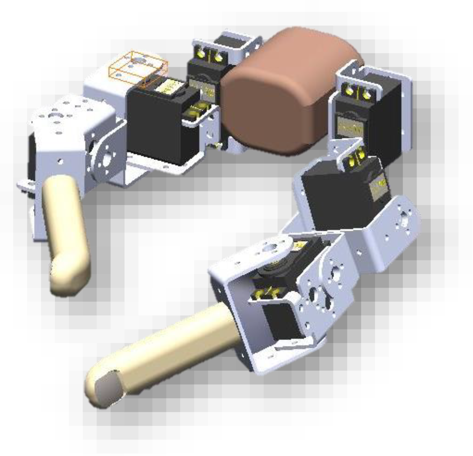
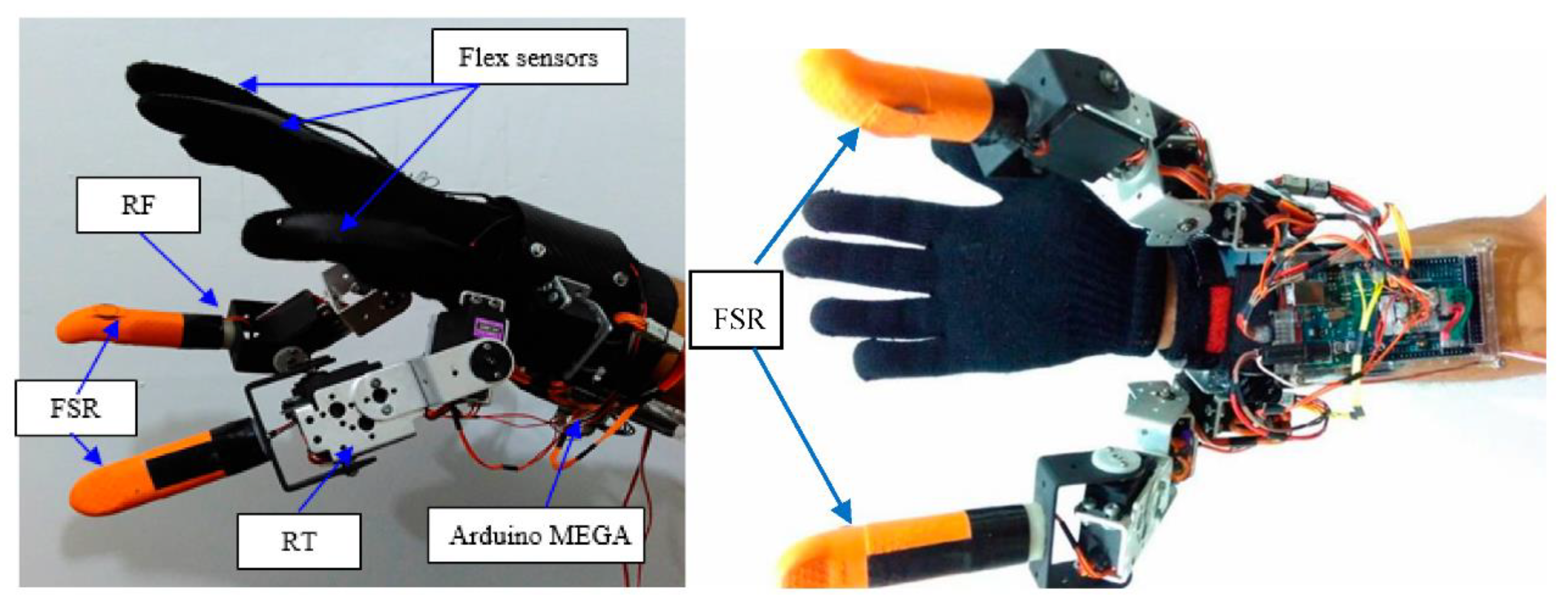
2.1. Extra Robotic Fingers Design and Prototyping
2.2. Extra Fingers’ Forward Kinematics
3. Data-Driven Coordination Control Based on Neural Network
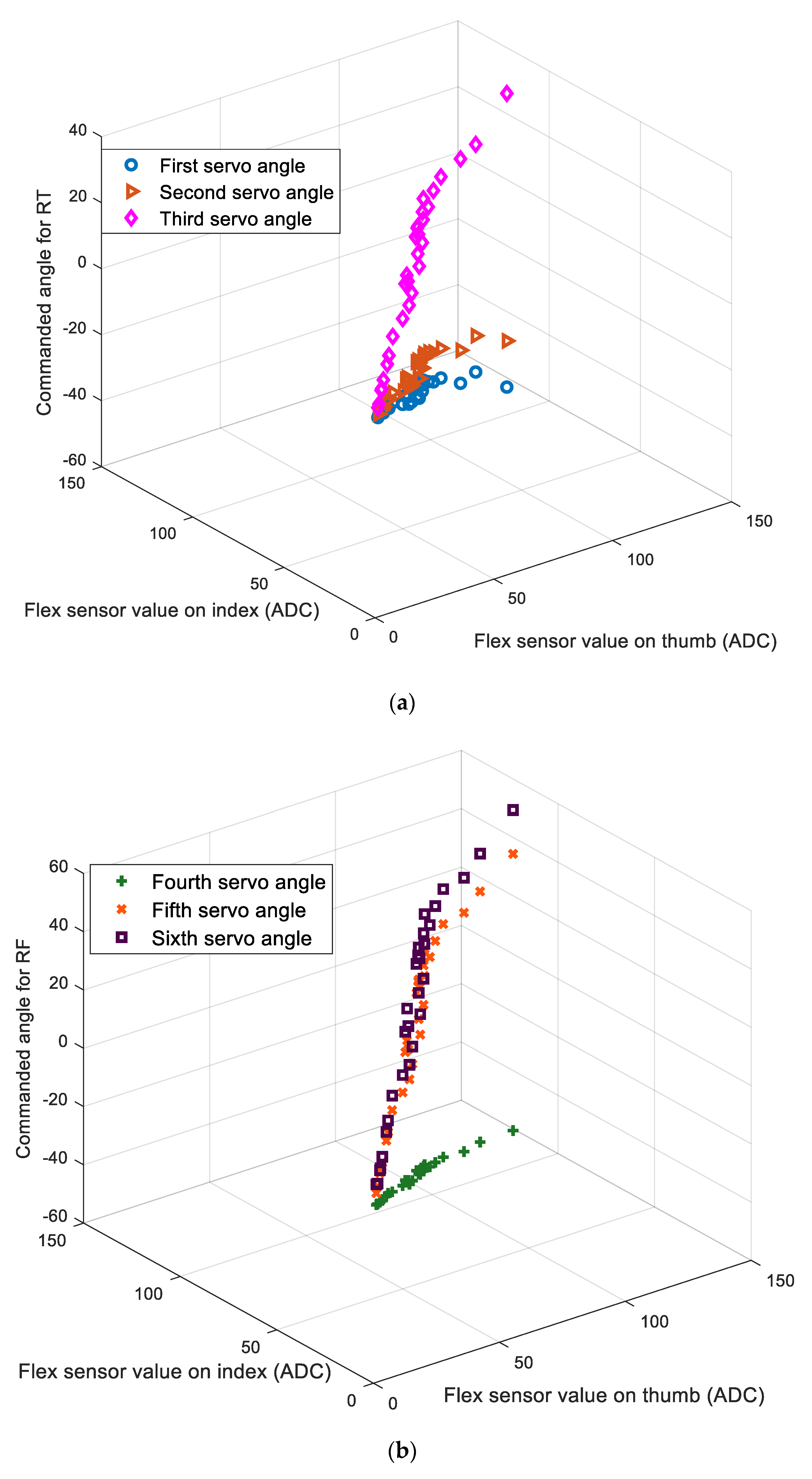
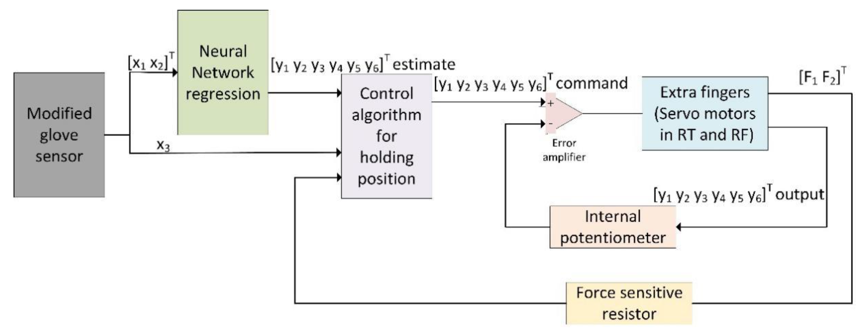
3.1. Grasp Posture Control
3.2. Position Hold Control
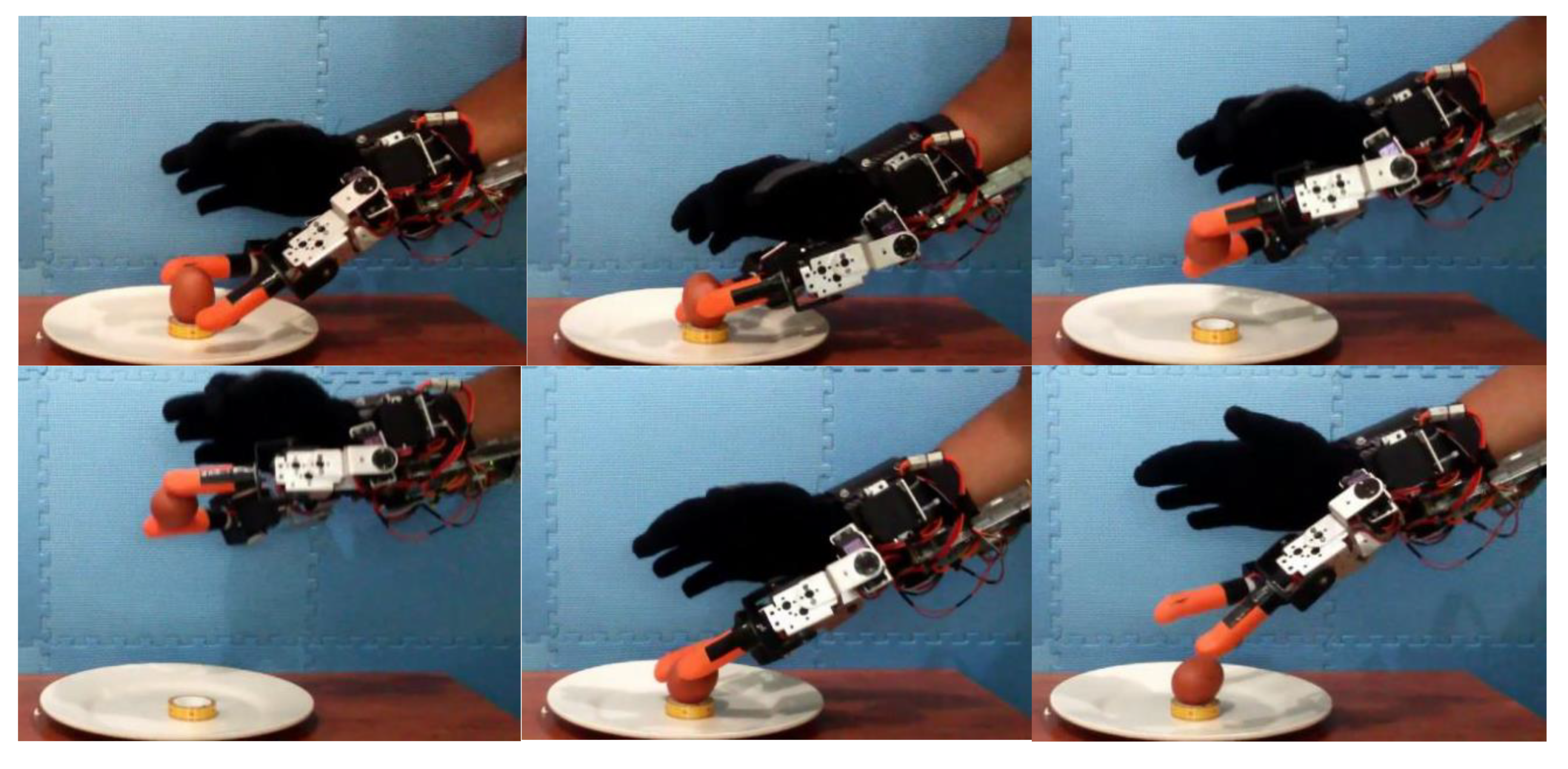
4. Bimanual Task Experiment and Discussion
5. Conclusions
Author Contributions
Funding
Acknowledgments
Conflicts of Interest
References
- Foumani, M.; Smith-Miles, K.; Gunawan, I. Scheduling of two-machine robotic rework cells: In-process, post-process and in-line inspection scenarios. Robot. Auton. Syst. 2017, 91, 210–225. [Google Scholar] [CrossRef]
- Foumani, M.; Gunawan, I.; Smith-Miles, K.; Ibrahim, M.Y. Notes on Feasibility and Optimality Conditions of Small-Scale Multifunction Robotic Cell Scheduling Problems with Pickup Restrictions. IEEE T. Ind. Inform. 2015, 11, 821–829. [Google Scholar] [CrossRef] [Green Version]
- Koprnický, J.; Najman, P.; Šafka, J. 3D printed bionic prosthetic hands. In Proceedings of the 2017 IEEE International Workshop of Electronics, Control, Measurement, Signals and their Application to Mechatronics (ECMSM), San Sebastian, Spain, 24–26 May 2017; pp. 1–6. [Google Scholar]
- Slade, P.; Akhtar, A.; Nguyen, M.; Bretl, T. Tact: Design and performance of an open-source, affordable, myoelectric prosthetic hand. In Proceedings of the 2015 IEEE International Conference on Robotics and Automation (ICRA), Seattle, WA, USA, 26–30 May 2015; pp. 6451–6456. [Google Scholar]
- Yoshikawa, M.; Sato, R.; Higashihara, T.; Ogasawara, T.; Kawashima, N. Rehand: Realistic electric prosthetic hand created with a 3D printer. In Proceedings of the 2015 37th Annual International Conference of the IEEE Engineering in Medicine and Biology Society (EMBC), Milan, Italy, 25–29 August 2015; pp. 2470–2473. [Google Scholar]
- Ariyanto, M.; Haryadi, G.D.; Ismail, R.; Pakpahan, J.A.; Mustaqim, K.A. A low cost anthropomorphic prosthetic hand using DC micro metal gear motor. In Proceedings of the 2016 3rd International Conference on Information Technology, Computer, and Electrical Engineering (ICITACEE), Semarang, Indonesia, 19–20 October 2016; pp. 42–46. [Google Scholar]
- Cipriani, C.; Controzzi, M.; Carrozza, M.C. Objectives, criteria and methods for the design of the SmartHand transradial prosthesis. Robotica 2010, 28, 919–927. [Google Scholar] [CrossRef] [Green Version]
- Su, Y.; Fisher, M.H.; Wolczowski, A.; Bell, G.D.; Burn, D.J.; Gao, R.X. Towards an EMG-Controlled Prosthetic Hand Using a 3-D Electromagnetic Positioning System. IEEE Trans. Instrum. Meas. 2007, 56, 178–186. [Google Scholar] [CrossRef]
- Jing, X.; Yong, X.; Jiang, Y.; Li, G.; Yokoi, H. Anthropomorphic Prosthetic Hand with Combination of Light Weight and Diversiform Motions. Appl. Sci. 2019, 9, 4203. [Google Scholar] [CrossRef] [Green Version]
- Benatti, S.; Milosevic, B.; Farella, E.; Gruppioni, E.; Benini, L. A Prosthetic Hand Body Area Controller Based on Efficient Pattern Recognition Control Strategies. Sensors 2017, 17, 869. [Google Scholar] [CrossRef] [Green Version]
- Tavakoli, M.; Batista, R.; Sgrigna, L. The UC Softhand: Light Weight Adaptive Bionic Hand with a Compact Twisted String Actuation System. Actuators 2016, 5, 1. [Google Scholar] [CrossRef] [Green Version]
- Au, S.K.; Herr, H.M. Powered ankle-foot prosthesis. IEEE Robot. Autom. Mag. 2008, 15, 52–59. [Google Scholar] [CrossRef]
- Martinez- Villalpando, E.C.; Weber, J.; Elliott, G.; Herr, H. Design of an agonist-antagonist active knee prosthesis. In Proceedings of the 2008 2nd IEEE RAS EMBS International Conference on Biomedical Robotics and Biomechatronics, Scottsdale, AZ, USA, 19–22 October 2008; pp. 529–534. [Google Scholar]
- Au, S.K.; Weber, J.; Herr, H. Biomechanical Design of a Powered Ankle-Foot Prosthesis. In Proceedings of the 2007 IEEE 10th International Conference on Rehabilitation Robotics, Noordwijk, The Netherlands, 12–15 June 2007; pp. 298–303. [Google Scholar]
- Bebionic Hand. Available online: https://www.ottobockus.com/prosthetics/upper-limb-prosthetics/solution-overview/bebionic-hand/ (accessed on 27 February 2020).
- Michelangelo Prosthetic Hand. Available online: https://www.ottobockus.com/prosthetics/upper-limb-prosthetics/solution-overview/michelangelo-prosthetic-hand/ (accessed on 20 February 2020).
- Open Bionics—Turning Disabilities into Superpowers. Available online: https://openbionics.com/ (accessed on 28 February 2020).
- Vincent Systems GmbH. Available online: https://vincentsystems.de/en/ (accessed on 1 March 2020).
- HACKberry |3D-Printable Open-Source Bionic Arm. Available online: http://exiii-hackberry.com/ (accessed on 29 March 2020).
- Wu, K.-Y.; Su, Y.-Y.; Yu, Y.-L.; Lin, C.-H.; Lan, C.-C. A 5-Degrees-of-Freedom Lightweight Elbow-Wrist Exoskeleton for Forearm Fine-Motion Rehabilitation. IEEE/ASME Trans. Mechatronics 2019, 24, 2684–2695. [Google Scholar] [CrossRef]
- Ismail, R.; Ariyanto, M.; Perkasa, I.A.; Adirianto, R.; Putri, F.T.; Glowacz, A.; Caesarendra, W. Soft Elbow Exoskeleton for Upper Limb Assistance Incorporating Dual Motor-Tendon Actuator. Electronics 2019, 8, 1184. [Google Scholar] [CrossRef] [Green Version]
- Vitiello, N.; Lenzi, T.; Roccella, S.; De Rossi, S.M.M.; Cattin, E.; Giovacchini, F.; Vecchi, F.; Carrozza, M.C. NEUROExos: A Powered Elbow Exoskeleton for Physical Rehabilitation. IEEE Trans. Robot. 2013, 29, 220–235. [Google Scholar] [CrossRef]
- Yun, S.-S.; Kang, B.B.; Cho, K.-J. Exo-Glove PM: An Easily Customizable Modularized Pneumatic Assistive Glove. IEEE Robot. Autom. Lett. 2017, 2, 1725–1732. [Google Scholar] [CrossRef]
- Gearhart, C.J.; Varone, B.; Stella, M.H.; BuSha, B.F. An effective 3-fingered augmenting exoskeleton for the human hand. In Proceedings of the 2016 38th Annual International Conference of the IEEE Engineering in Medicine and Biology Society (EMBC), Orlando, FL, USA, 16–20 August 2016; pp. 590–593. [Google Scholar]
- Ivanescu, M.; Popescu, N.; Popescu, D.; Channa, A.; Poboroniuc, M. Exoskeleton Hand Control by Fractional Order Models. Sensors 2019, 19, 4608. [Google Scholar] [CrossRef] [Green Version]
- Antonellis, P.; Galle, S.; Clercq, D.D.; Malcolm, P. Altering gait variability with an ankle exoskeleton. PLoS ONE 2018, 13, e0205088. [Google Scholar] [CrossRef] [Green Version]
- Malcolm, P.; Galle, S.; Derave, W.; De Clercq, D. Bi-articular Knee-Ankle-Foot Exoskeleton Produces Higher Metabolic Cost Reduction than Weight-Matched Mono-articular Exoskeleton. Front. Neurosci. 2018, 12, 69. [Google Scholar] [CrossRef] [Green Version]
- Louie, D.R.; Eng, J.J. Powered robotic exoskeletons in post-stroke rehabilitation of gait: A scoping review. J. NeuroEng. Rehabil. 2016, 13, 53. [Google Scholar] [CrossRef] [Green Version]
- Jones, C.L.; Wang, F.; Morrison, R.; Sarkar, N.; Kamper, D.G. Design and Development of the Cable Actuated Finger Exoskeleton for Hand Rehabilitation Following Stroke. IEEE/ASME Trans. Mechatronics 2014, 19, 131–140. [Google Scholar] [CrossRef]
- Treers, L.; Lo, R.; Cheung, M.; Guy, A.; Guggenheim, J.; Parietti, F.; Asada, H. Design and Control of Lightweight Supernumerary Robotic Limbs for Sitting/Standing Assistance. In Proceedings of the 2016 International Symposium on Experimental Robotics, Tokyo, Japan, 3–6 October 2016; Kulić, D., Nakamura, Y., Khatib, O., Venture, G., Eds.; Springer International Publishing: Cham, Switzerland, 2017; pp. 299–308. [Google Scholar]
- Parietti, F.; Chan, K.C.; Hunter, B.; Asada, H.H. Design and control of Supernumerary Robotic Limbs for balance augmentation. In Proceedings of the 2015 IEEE International Conference on Robotics and Automation (ICRA), Seattle, WA, USA, 26–30 May 2015; pp. 5010–5017. [Google Scholar]
- Parietti, F.; Asada, H.H. Supernumerary Robotic Limbs for aircraft fuselage assembly: Body stabilization and guidance by bracing. In Proceedings of the 2014 IEEE International Conference on Robotics and Automation (ICRA), Hong Kong, China, 31 May–7 June 2014; pp. 1176–1183. [Google Scholar]
- Sasaki, T.; Saraiji, M.Y.; Fernando, C.L.; Minamizawa, K.; Inami, M. MetaLimbs: Multiple arms interaction metamorphism. In Proceedings of the ACM SIGGRAPH 2017 Emerging Technologies, SIGGRAPH 2017, Los Angeles, CA, USA, 30 July–3 August 2017; Association for Computing Machinery, Inc.: New York, NY, USA, 2017; p. 16. [Google Scholar]
- Llorens-Bonilla, B.; Asada, H.H. Control and Coordination of Supernumerary Robotic Limbs Based on Human Motion Detection and Task Petri Net Model; American Society of Mechanical Engineers Digital Collection: New York, NY, USA, 2014. [Google Scholar]
- Wu, F.Y.; Asada, H. Bio-Artificial Synergies for Grasp Posture Control of Supernumerary Robotic Fingers. In Proceedings of the in Robotics: Science and Systems X, University of California, Berkeley, CA, USA, 12–16 July 2014. [Google Scholar]
- Wu, F.Y.; Asada, H.H. Implicit and Intuitive Grasp Posture Control for Wearable Robotic Fingers: A Data-Driven Method Using Partial Least Squares. IEEE Trans. Robot. 2016, 32, 176–186. [Google Scholar] [CrossRef]
- Wu, F.Y.; Asada, H.H. “Hold-and-manipulate” with a single hand being assisted by wearable extra fingers. In Proceedings of the 2015 IEEE International Conference on Robotics and Automation (ICRA), Seattle, WA, USA, 26–30 May 2015; pp. 6205–6212. [Google Scholar]
- Ort, T.; Wu, F.; Hensel, N.C.; Asada, H.H. Supernumerary Robotic Fingers as a Therapeutic Device for Hemiparetic Patients; American Society of Mechanical Engineers Digital Collection: New York, NY, USA, 2016. [Google Scholar]
- Segura Meraz, N.; Sobajima, M.; Aoyama, T.; Hasegawa, Y. Modification of body schema by use of extra robotic thumb. ROBOMECH J. 2018, 5, 3. [Google Scholar] [CrossRef] [Green Version]
- Zhu, Y.; Ito, T.; Aoyama, T.; Hasegawa, Y. Development of sense of self-location based on somatosensory feedback from finger tips for extra robotic thumb control. ROBOMECH J. 2019, 6, 7. [Google Scholar] [CrossRef]
- Hussain, I.; Spagnoletti, G.; Salvietti, G.; Prattichizzo, D. An EMG Interface for the Control of Motion and Compliance of a Supernumerary Robotic Finger. Front. Neurorobot. 2016, 10, 18. [Google Scholar] [CrossRef] [PubMed] [Green Version]
- Hussain, I.; Salvietti, G.; Spagnoletti, G.; Prattichizzo, D. The Soft-SixthFinger: A Wearable EMG Controlled Robotic Extra-Finger for Grasp Compensation in Chronic Stroke Patients. IEEE Robot. Autom. Lett. 2016, 1, 1000–1006. [Google Scholar] [CrossRef] [Green Version]
- Prattichizzo, D.; Malvezzi, M.; Hussain, I.; Salvietti, G. The Sixth-Finger: A modular extra-finger to enhance human hand capabilities. In Proceedings of the 23rd IEEE International Symposium on Robot and Human Interactive Communication, Edinburgh, UK, 25–29 August 2014; pp. 993–998. [Google Scholar]
- Salvietti, G.; Hussain, I.; Cioncoloni, D.; Taddei, S.; Rossi, S.; Prattichizzo, D. Compensating Hand Function in Chronic Stroke Patients Through the Robotic Sixth Finger. IEEE Trans. Neural Syst. Rehabil. Eng. 2017, 25, 142–150. [Google Scholar] [CrossRef] [PubMed]
- Hussain, I.; Salvietti, G.; Malvezzi, M.; Prattichizzo, D. Design guidelines for a wearable robotic extra-finger. In Proceedings of the 2015 IEEE 1st International Forum on Research and Technologies for Society and Industry Leveraging a better tomorrow (RTSI), Torino, Italy, 16–18 September 2015; pp. 54–60. [Google Scholar]
- Ariyanto, M.; Ismail, R.; Nurmiranto, A.; Caesarendra, W.; Franke, J. Development of a low cost anthropomorphic robotic hand driven by modified glove sensor and integrated with 3D animation. In Proceedings of the 2016 IEEE EMBS Conference on Biomedical Engineering and Sciences (IECBES), Kuala Lumpur, Malaysia, 4–7 December 2016; pp. 341–346. [Google Scholar]
- Ariyanto, M.; Ismail, R.; Setiawan, J.D.; Arifin, Z. Development of low cost supernumerary robotic fingers as an assistive device. In Proceedings of the 2017 4th International Conference on Electrical Engineering, Computer Science and Informatics (EECSI), Yogyakarta, Indonesia, 19–21 September 2017; pp. 1–6. [Google Scholar]


| Link | ai (mm) | αi (Degree) | di (mm) | θi (Degree) |
|---|---|---|---|---|
| 1 | 25 | 90° | 0 | θ1 |
| 2 | 75 | 90° | 0 | θ2 |
| 3 | 116 | 0° | 0 | θ3 |
| 4 | 25 | 90° | 0 | θ4 |
| 5 | 75 | 0° | 0 | θ5 |
| 6 | 116 | 0° | 0 | θ6 |
| NN Parameters | Value |
|---|---|
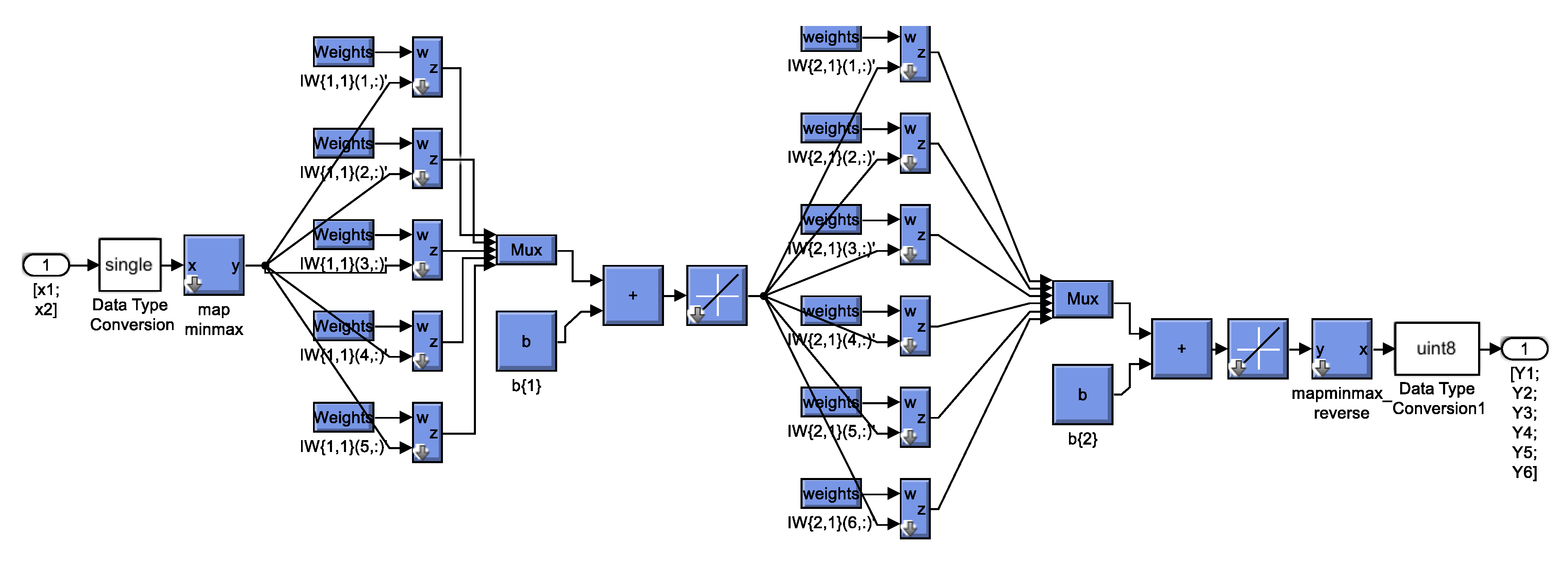
| Model | Feedforward neural network |
| Number of neurons in hidden layer | 5 |
| Number of neurons in output layer | 6 |
| Divide Parameter | Random |
| Ratio of Training | 70% |
| Ratio of Validation | 15% |
| Ratio of Testing | 15% |
| Training Algorithm | Levenberg-Marquardt backpropagation |
| Maximum Epoch | 1000 |
| Performance Goal | 0.001 |
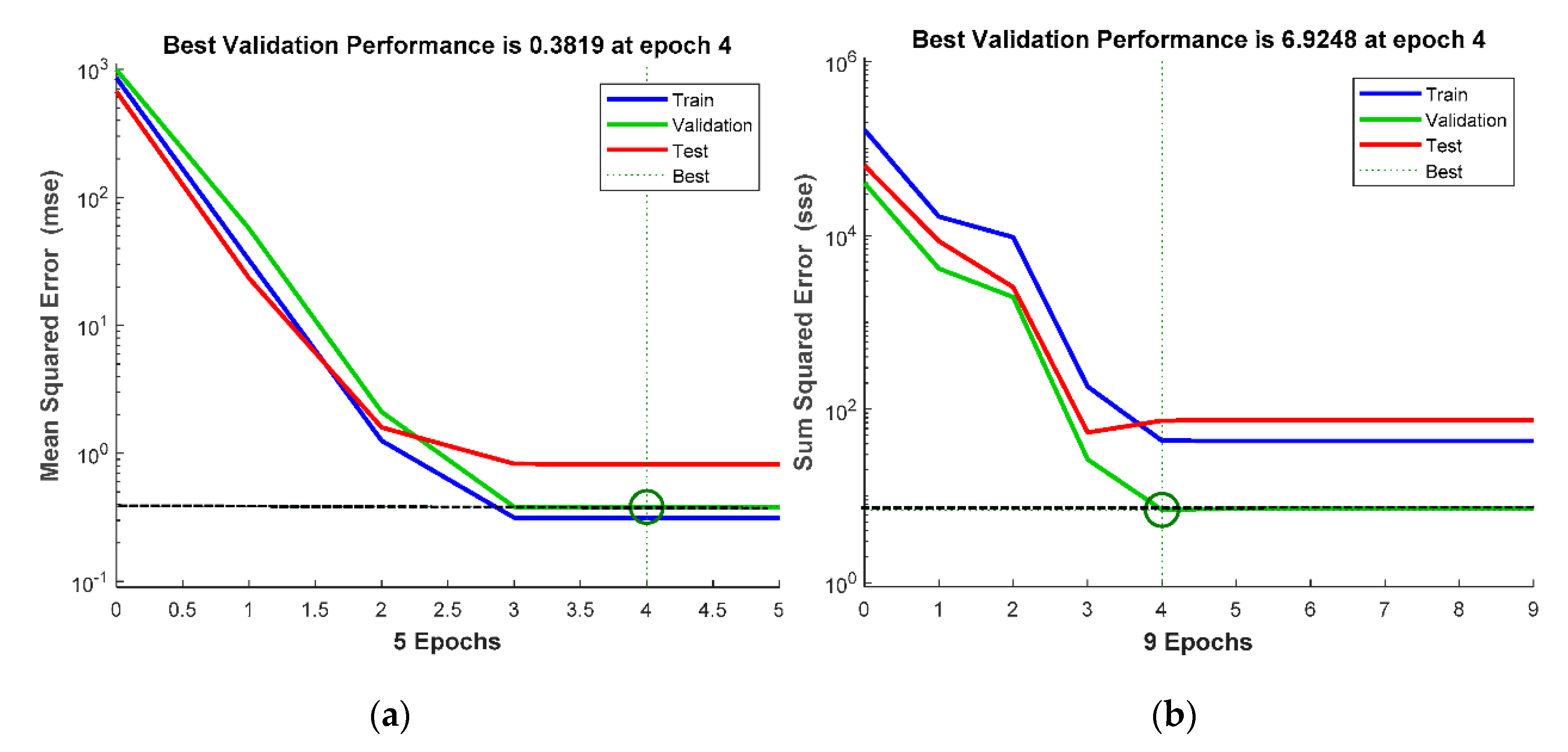
| Error performance | Mean squared error (MSE) Sum squared error (SSE) |
| Transfer function of hidden layer | Linear transfer function |
| Transfer function of output layer | Linear transfer function |
| Error Performance | R | |||
|---|---|---|---|---|
| Training | Validation | Test | Overall | |
| MSE | 0.9997 | 0.9999 | 0.9994 | 0.9997 |
| SSE | 0.9997 | 0.9998 | 0.9993 | 0.9995 |
| x3 > Threshold | F1 > Threshold | F2 > Threshold | Position Hold Control |
|---|---|---|---|
| 0 | 0 | 0 | inactive |
| 0 | 0 | 1 | active |
| 0 | 1 | 0 | active |
| 0 | 1 | 1 | active |
| 1 | 0 | 0 | active |
| 1 | 0 | 1 | active |
| 1 | 1 | 0 | active |
| 1 | 1 | 1 | active |
| Object Manipulation | Bimanual Task Results |
|---|---|
| Lifting and stirring water and sugar in an aluminum mug |  |
| Grasping and lifting volleyball |  |
| Lifting and opening a bottle cap |  |
| Unplugging the AC power plug from the extension cord reel |  |
| Opening first jar lid |  |
| Opening second jar lid |  |
| Tightening a bolt to electronic components |  |
| Operating a 6" tablet | 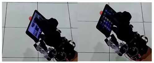 |
| Taking and lifting the dipper and bucket simultaneously | 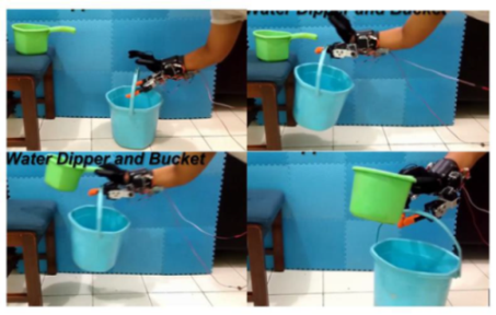 |
| Operating an 8" tablet |  |
| Object Manipulation | Success | Failure | ||
|---|---|---|---|---|
| Missed Object | Object Slipped | Extra Fingers Obstruct the Grasp | ||
| Aluminum mug | 5/8 | 1/8 | 1/8 | 1/8 |
| Volleyball | 6/8 | 1/8 | 0/8 | 1/8 |
| Bottled-water | 4/8 | 2/8 | 2/8 | 0/8 |
| Extension cord reel | 7/8 | 0/8 | 0/8 | 1/8 |
| First jar lid | 5/8 | 2/8 | 0/8 | 1/8 |
| Second jar lid | 6/8 | 1/8 | 1/8 | 0/8 |
| Tighten a bolt | 5/8 | 2/8 | 0/8 | 1/8 |
| Dipper and bucket | 8/8 | 0/8 | 0/8 | 0/8 |
| 6” tablet | 7/8 | 1/8 | 0/8 | 0/8 |
| 8” tablet | 8/8 | 0/8 | 0/8 | 0/8 |
| Egg | 4/8 | 3/8 | 1/8 | 0/8 |
© 2020 by the authors. Licensee MDPI, Basel, Switzerland. This article is an open access article distributed under the terms and conditions of the Creative Commons Attribution (CC BY) license (http://creativecommons.org/licenses/by/4.0/).
Share and Cite
Setiawan, J.D.; Ariyanto, M.; Munadi, M.; Mutoha, M.; Glowacz, A.; Caesarendra, W. Grasp Posture Control of Wearable Extra Robotic Fingers with Flex Sensors Based on Neural Network. Electronics 2020, 9, 905. https://doi.org/10.3390/electronics9060905
Setiawan JD, Ariyanto M, Munadi M, Mutoha M, Glowacz A, Caesarendra W. Grasp Posture Control of Wearable Extra Robotic Fingers with Flex Sensors Based on Neural Network. Electronics. 2020; 9(6):905. https://doi.org/10.3390/electronics9060905
Chicago/Turabian StyleSetiawan, Joga Dharma, Mochammad Ariyanto, M. Munadi, Muhammad Mutoha, Adam Glowacz, and Wahyu Caesarendra. 2020. "Grasp Posture Control of Wearable Extra Robotic Fingers with Flex Sensors Based on Neural Network" Electronics 9, no. 6: 905. https://doi.org/10.3390/electronics9060905
APA StyleSetiawan, J. D., Ariyanto, M., Munadi, M., Mutoha, M., Glowacz, A., & Caesarendra, W. (2020). Grasp Posture Control of Wearable Extra Robotic Fingers with Flex Sensors Based on Neural Network. Electronics, 9(6), 905. https://doi.org/10.3390/electronics9060905