Article

Grasp Posture Control of Wearable Extra Robotic Fingers with Flex Sensors Based on Neural Network

1
Department of Mechanical Engineering, Faculty of Engineering, Diponegoro University, Semarang 50275, Indonesia
2
Center for Biomechanics, Biomaterials, Biomechantronics and Biosignal processing (CBIOM3S), Diponegoro University, Semarang 50275, Indonesia
3
AGH University of Science and Technology, aleja Adama Mickiewicza 30, 30-059 Kraków, Poland
4
Faculty of Integrated Technologies, Universiti Brunei Darussalam, Jalan Tungku Link, Gadong BE1410, Brunei
*
Authors to whom correspondence should be addressed.
Electronics 2020, 9(6), 905; https://doi.org/10.3390/electronics9060905
Submission received: 10 May 2020 / Revised: 24 May 2020 / Accepted: 27 May 2020 / Published: 29 May 2020
(This article belongs to the Section Artificial Intelligence)

Abstract

:
This study proposes a data-driven control method of extra robotic fingers to assist a user in bimanual object manipulation that requires two hands. The robotic system comprises two main parts, i.e., robotic thumb (RT) and robotic fingers (RF). The RT is attached next to the user’s thumb, while the RF is located next to the user’s little finger. The grasp postures of the RT and RF are driven by bending angle inputs of flex sensors, attached to the thumb and other fingers of the user. A modified glove sensor is developed by attaching three flex sensors to the thumb, index, and middle fingers of a wearer. Various hand gestures are then mapped using a neural network. The input data of the robotic system are the bending angles of thumb and index, read by flex sensors, and the outputs are commanded servo angles for the RF and RT. The third flex sensor is attached to the middle finger to hold the extra robotic finger’s posture. Two force-sensitive resistors (FSRs) are attached to the RF and RT for the haptic feedback when the robot is worn to take and grasp a fragile object, such as an egg. The trained neural network is embedded into the wearable extra robotic fingers to control the robotic motion and assist the human fingers in bimanual object manipulation tasks. The developed extra fingers are tested for their capacity to assist the human fingers and perform 10 different bimanual tasks, such as holding a large object, lifting and operate an eight-inch tablet, and lifting a bottle, and opening a bottle cap at the same time.

1. Introduction

The use of robotic arms is typically common in manufacturing and service operations [1,2]. The current research is more focused on robots that can be worn due to the growing demand for them. The most widely known of these types of robots are prosthesis and exoskeleton robots. A prosthesis is used to replace the lost limbs of humans due to accidents or birth defects. Many researchers around the world have developed myoelectric prosthetic hands to replace and add upper limbs, [3,4,5,6,7,8,9,10,11], and ankle/foot prosthesis for the lower limb [12,13,14]. Several researchers have attempted to make the cost of the prosthetic hand more affordable, by utilizing 3D printer technologies [3,4,5] and tendon mechanisms [6]. The researchers in Italy strive to replicate the human hand as closely as possible, by developing 16 degrees of freedom and 40 sensors for their prosthetic hand [7]. One method for simplifying the classification procedure of electromyography (EMG) signals was proposed in [8], by using novel 3D electromagnetic positioning sensors. Lightweight prosthetic hands were designed by considering the trade-off between dexterity and cost [9,11]. Support Vector Machine (SVM) classification with a high-level Finite State Machine (FSM) was used to produce accurate and robust control in [10]. These kinds of wearable robots have become established and commercialized products, and are widely available on the market today [15,16,17,18,19]. The bebionic hand from Ottobock has 14 different grip patterns and hand positions [15]. This hand utilizes lead screw motors as the main actuators and linkage as the joint couple method. The Michelangelo hand from Ottobock has seven grip patterns and position modes [16]. The hand utilizes cam design in all fingers as the joint couple method. The Vincent hand uses four motors on individual fingers and two motors on the thumb, for supporting 14 grasp patterns that can be chosen with single trigger control [18] The affordable and opensource myoelectric hands were developed by Open Bionics [17] and exiii HACKberry [19]. These hands are based on 3D printer technology, which makes them lightweight. Open Bionics employ linear actuator and exiii HACKberry utilizes servo motors as the main actuators. The second most commonly used wearable robot is an exoskeleton. This type of robot is worn to provide mechanical support for diminished limb function due to stroke, accident, or other diseases. The exoskeleton robots are worn by a wearer to support mechanical force and to assist human joints such as the elbow [20,21,22], finger/hand [23,24,25], and ankle/foot [26,27]. This type of robot has been developed by using hard and soft robot technology. Many results in the study show that a soft robot has more benefits and greater convenience for use as an exoskeleton, providing mechanical support and force, because of the characteristics of the utilized materials compared to hard robot materials. The robot is also widely used as a stroke rehabilitation device [28,29].
The third type of wearable robot is a supernumerary robotic limb (SRL). This SRL is a robot that adds more robotic limbs for the user, to provide mechanical assistance. Unlike an exoskeleton robot, this kind of robot moves independently from the skeletal user’s limbs. The robotic limbs that can be added are arms, fingers, and legs. The developed supernumerary robotic leg can provide balance assistance or sitting/standing assistance [30,31]. Supernumerary robotic arms are worn to provide mechanical support and assist a wearer in performing a task [32,33,34]. The last added robotic limbs are supernumerary/extra robotic fingers.
Supernumerary robotic fingers (SRFs) are additional/extra robotic fingers, which move in a way that mimics the movements of a human finger. SRF development has different objectives, ranging from industrial applications to assistive medical devices. Most of these robots are designed and developed as a device to assist users in the task of bimanual object manipulation. The most challenging issue for this type of robot is to coordinate grasp posture control between the wearer’s fingers and the robotic fingers. Most SRFs are used to provide physical assistance when the wearer performs bimanual object manipulation. This coordination can usually be done using two normal healthy hands, and it is challenging to perform bimanual object manipulation using only one hand.
Researchers at Massachusetts Institute of Technology (MIT) have successfully created an SRF for bimanual object manipulation [35,36,37,38]. This SRF consists of two additional robotic fingers placed next to the user’s thumb and little finger. Partial least square (PLS) regression is applied for grasp posture control of the developed SRF. The proposed SRFs can be worn to provide physical assistance in bimanual object grasping manipulation. Some researchers have built an extra robotic thumb [39,40]. Other researchers have developed extra robotic fingers or sixth fingers, as presented in [41,42,43,44,45]. The developed extra finger successfully enhances manipulation dexterity and enlarges the wearer’s workspace. The robots are also able to assist chronic stroke patients.
In this study, a new type of wearable robot is developed for providing mechanical assistance in bimanual object manipulation tasks. A data-driven control method using neural network regression is applied to control the wearable extra robotic finger’s motion more intuitively and efficiently. A flex sensor is applied to read the bending motion from the user's thumb, index, and middle fingers. These signals will be fed to the trained neural network regression to estimate the commanded angles for the servo motors in the extra robotic fingers. The prototype is also equipped with force-sensitive resistors (FSRs), and these are attached to the fingertips of the extra robotic fingers to incorporate a haptic feedback system. The developed extra robotic fingers are worn on the user's healthy hand for providing assistance in bi-manual manipulation tasks.
The remaining sections of this study are organized as follows: The design and forward kinematics of the extra robotic fingers are presented in Section 2. The data-driven method utilizing neural network regression for extra robotic posture control is summarized in Section 3. The results of the bimanual manipulation tasks are given in Section 4. The summary of conclusions is written in Section 5.

2. Extra Two Robotic Fingers

This section comprises two subsections, which generally present the following content: (1) The extra robotic fingers’ (ERF) design, sensors, microcontrollers, actuators, and other electronic components are discussed in the first subsection. (2) The second subsection presents forward kinematics for the fingertip motions of the RT and RF. This kinematics method is utilized to estimate the RT and RF tip trajectories when they are given with predefined input angles. Finally, the forward kinematics formula will be computed using the Denavit–Hartenberg (DH) parameter to estimate the fingertip trajectories of the RT and RF.

2.1. Extra Robotic Fingers Design and Prototyping

In developing the extra robotic fingers for providing mechanical assistance in bimanual object manipulation, the 3D model of the extra robotic fingers is adjusted to the dimensions of the required components and the size of the user's hand. A 3D design is carried out in a SolidWorks 3D CAD design Software environment. The 3D design of the proposed extra robotic fingers is shown in Figure 1. The proposed wearable extra robotic fingers consist of a robotic thumb (RT), which is attached near the thumb of the user’s hand, and the robotic finger (RF), which is placed next to the index finger of the user’s hand. Both the RT and RF are designed with three degrees of freedom (DOF). The extra fingers are driven by six servo motors. The initial length of the extra fingers for both the RT and RF, in the longitudinal axis, is 216 mm.
The RT’s mechanism is designed by mimicking a human's thumb motion. It moves like a human thumb, performing circumduction, abduction, and flexion. The motion of the RF is designed by imitating the other four human fingers. The intended motions for the RT are abduction and two flexions. The fingertips of the extra robotic fingers are designed to resemble the shape of a human finger, and are manufactured using a 3D printer. Servo brackets are used to separate one servo motor from another servo.
The initial design of this study was inspired by research that has been developed by Faye Wu, and H. Harry Asada at MIT [35,36], with sensor and actuator components that are adjusted according to study needs. Wearable extra robotic fingers are designed using an analog servo motor as the main actuator. The analog servo motor used is a double shaft servo type. In this study, 850 mAh two-cell batteries with an output of 7.4 V, and 500 mAh two-cell batteries with an output of 7.4 V, are utilized. The first battery is used for powering the six servo motors, while the second battery provides the electrical power for a microcontroller. The microcontroller used for the extra robotic fingers’ computing center is the Arduino Mega 2560. It has 54 DIO pins, with 14 pins that can be utilized for PWM outputs and another 16 pins for the analog input pins, four pins for UART, as well as 16 MHz oscillators, USB connections, and an ICSP Header. According to the specifications of the microcontroller, Arduino MEGA is very suitable as a neural network regression computing center to move the extra robotic fingers. Two FSRs are attached to the fingertips of the RT and RF, as shown in Figure 2.
The total mass of the wearable extra robotic fingers, excluding the mass of two batteries and an Arduino microcontroller, is 650 g. This mass is quite light when a user wears it on his right hand. Two batteries are placed in the wearer's pocket to decrease the total robot mass. To reduce the torque needed by the robot, a metal bracket is applied to join the two servo motors. An Arduino microcontroller is placed below the wrist of the user's hand. A Tower Pro MG 995 servo motor is selected for the main actuator of the robot. It can generate torque up to 9.4 kg/cm at 4.8 V. This torque is sufficient for the proposed wearable extra robotic fingers.
In bimanual object manipulation tasks, the proposed extra robotic fingers must work together with the user's fingers. Three flex sensors, with a length of 2.2 inches, are selected to estimate the bending angle of the user’s fingers. This kind of sensor has been successfully applied in a teleoperated robotic hand [46]. The flex sensor is a sensor that works to detect curvature. The voltage divider circuit is used as a circuit to convert the changes in resistance value into the voltage changes when the flex sensor is bent. The bending reading results from the flex sensor attached to the user's fingers are applied as the input signal for driving the six servo motors. A resistor of 22 K ohm is selected in the flex sensor circuit for data acquisition of the voltage change generated on the flex sensor. The arrangement and attachment of the flex sensors can be seen in Figure 3. The glove from iGlove is selected because it can be worn to operate the touchscreen on a smartphone and tablet computer. The thumb, index, and middle fingers are used as grasp posture inputs for wearable extra robotic fingers.

2.2. Extra Fingers’ Forward Kinematics

Forward kinematics is carried out to predict the fingertip trajectory for both the RT and RF. The fingertip trajectory can be obtained by providing the angle data input for the six servo motors. This trajectory can be used to determine the working space of the extra robotic fingers. DH parameters are extracted from the proposed wearable extra fingers for the RT and RF. Table 1 summarizes the DH parameters for the developed extra robotic fingers. The acquired parameters in this table are used as the parameters for computation in the DH transformation matrix, as expressed in Equation (1).
T = n = 1 3 [ cos θ i sin θ i cos α i sin θ i sin α i a i cos θ i sin θ i cos θ i cos α i cos θ i sin α i a i sin θ i 0 sin α i cos α i d i 0 0 0 1 ]
By computing the transformation matrix for both the RT and RF, the three-dimensional space of the fingertip position can be generated. The fingertip position of the RT is expressed by Equations (2) to (4), while the fingertip trajectory for the RF is written in Equations (5) to (7).
X R T = a 1 cos θ 1 + a 2 cos θ 1 cos θ 2 + a 3 sin θ 1 sin θ 3 + a 3 cos θ 1 cos θ 2 cos θ 3
Y R T = a 1 sin θ 1 + a 2 sin θ 1 cos θ 2 a 3 cos θ 1 sin θ 3 + a 3 sin θ 1 cos θ 2 cos θ 3
Z R T = a 2 sin θ 2 + a 3 sin θ 2 cos θ 3
X RF = a 4 cos θ 4 + a 5 cos θ 4 cos θ 5 + a 6 cos θ 4 cos θ 5 cos θ 6 a 6 cos θ 4 sin θ 5 sin θ 6
Y RF = a 4 sin θ 4 + a 5 sin θ 4 cos θ 5 + a 6 sin θ 4 cos θ 5 cos θ 6 a 6 sin θ 4 sin θ 5 sin θ 6
Z RF = a 5 sin θ 6 + a 6 cos θ 5 sin θ 6 + a 6 sin θ 5 cos θ 6

3. Data-Driven Coordination Control Based on Neural Network

3.1. Grasp Posture Control

In this section, the data-driven method based on a neural network is presented and discussed. Neural network regression is applied to grasp posture control for the extra two robotic fingers. In the previous study [47], the extra robotic fingers were controlled using a linear constant-coefficient matrix, without implementing the position hold control coming from the FSR sensors. The matrix was used to multiply the signal inputs sourced from the flex sensors into commanded angles for driving the six servo motors. The robot was worn on the healthy right hand to provide mechanical assistance in bimanual object grasping manipulations, such as: (a) grasping and holding bottle, and opening the bottle cap at the same time; (b) grasping and lifting a volleyball; and (c) lifting and holding a glass while stirring with a spoon. Based on the experimental results, the extra robotic fingers did not perform intuitive control for the extra robotic finger movements commanded by the user’s thumb and index finger. The user needed to be careful and slowly move the index and middle finger when holding an object with the robot fingertips touching the surface of the object. Researchers at MIT have developed grasp posture control for SRFs using PLS regression [35,36,37]. By applying the PLS regression method, experimental results reveal that the developed SRFs can assist with object grasping manipulation in bimanual tasks such as grasping a basketball, holding and operating a tablet computer, and taking and grasping bottled-water.
In this study, the grasping posture of the developed extra two robotic fingers is controlled using neural network regression. A feed-forward neural network structure is selected in the data-driven method for controlling the motion of the RT and RF. Considering the memory and the speed of the Arduino MEGA microcontroller, the selected number of neurons is five neurons. The number of neurons in the hidden layer is kept as low as possible, to reduce the computation burden in the Arduino MEGA microcontroller. The Levenberg–Marquardt backpropagation method is chosen for the training algorithm for neural network regression, with the maximum epoch of 1000. A linear transfer function is implemented on the neural network for both the hidden layer and the output layer. The selected neural network regression parameters are summarized in Table 2.
In the neural network regression training, 0.001 is selected as the performance goal for the error. The input data set is divided into three subsets—training, validation, and testing—which are selected randomly. The ratios of the data sets for training, testing, and validation are 70%, 15%, and 15%, respectively. Mean squared error (MSE) and sum squared error (SSE) are selected and used as performance functions during training. The formulas for calculating MSE and SSE are expressed in Equations (8) and (9), respectively. These error performances will be used to identify the best neural network regression for the developed extra robotic fingers. The smaller the value of MSE and SSE, the better the regression model. R-value is used to select the better performance result between MSE and SSE. The R-value can be computed using Equation (10)
MSE = i = 1 n ( y i y i ) 2 N
SSE = i = 1 n ( y i y i ) 2
R = 1 i = 1 n ( y i y i ) 2 i = 1 n ( y i ) 2
where y i is the actual value from the data set, and y i is the estimated output from the actual value. N is the number of data. R computes the fitting degree between actual values and estimated values. The range of R is mapped from 0 to 1; the 0 value of R shows the worst performance of the regression, while 1 value reveals the best regression performance. Before the actual values go to the neural network regression, all data are normalized between −1 and 1, as expressed in Equation (11). The inverse function of Equation (11) will be used as a denormalized function from the neural network regression output to the estimated value.
y = ( y max y min ) × ( x x min ) x max x min + y min
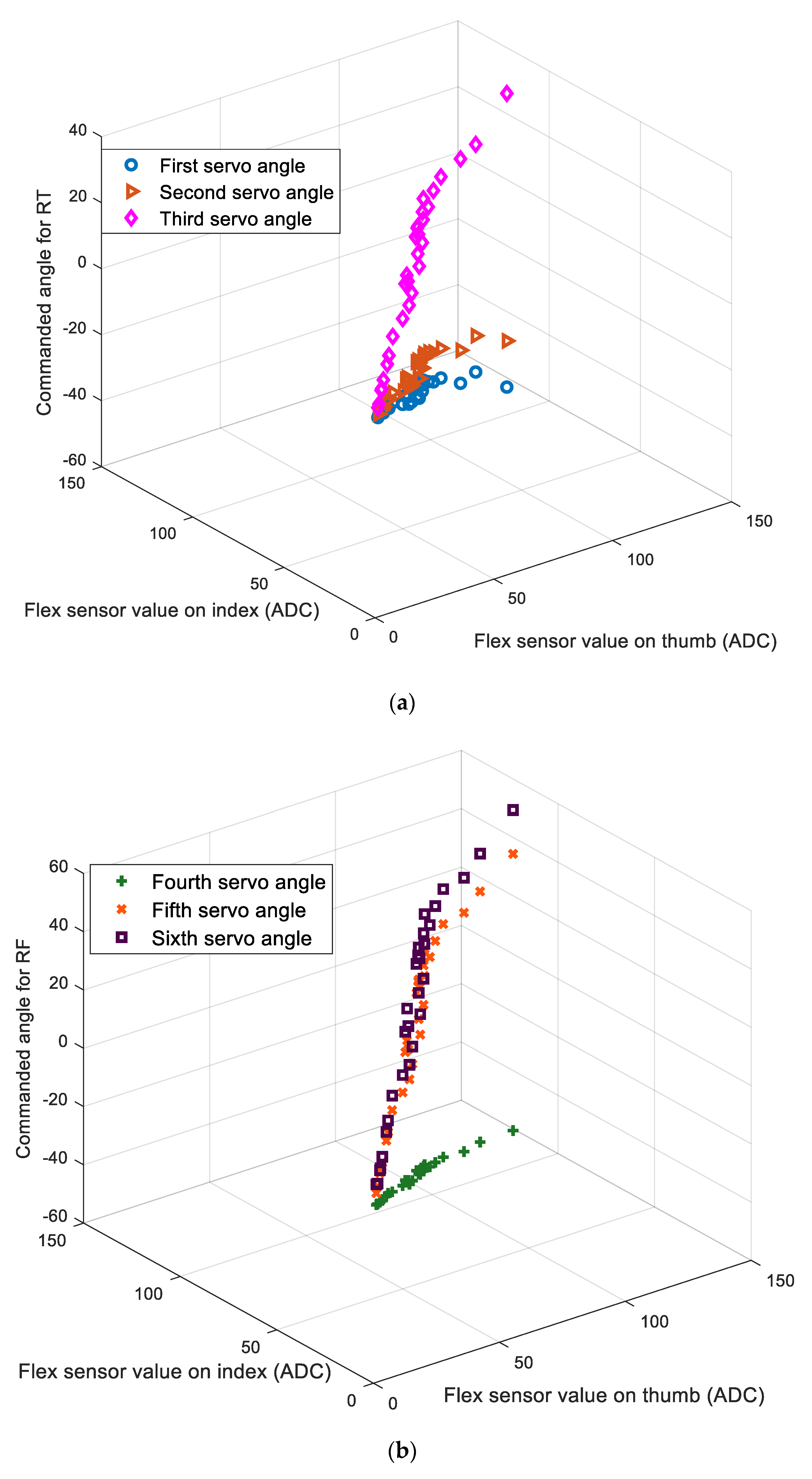
Data acquisition (DAQ) of input and output data is conducted by providing movement to the developed wearable extra robotic fingers. Input data are obtained from the flex sensor readings when the thumb (x1) and the user’s index finger (x2) are bent. The output in the data set is the joint angle command given to the three servo motors [y1,y2,y3] on the RT and the three servo motors [y4,y5,y6] on the RF. The input−output data are collected from the smallest bending angle to the maximum bending angle carried out by the thumb and index fingers. The amount of input and output data obtained is 30 points for each x1, x2, y1, y2, y3, y4, y5, and y6. The data size for the input is a matrix with a size of 30 × 2, while the output data is a matrix with a size of 30 × 6. Five input data points are obtained by grasping some objects, such as a volleyball, an aluminum mug, a bottle and two jars with different sizes, while 25 other data points are determined by taking quiet linear data points, as shown in Figure 4a for RT and Figure 4b for RF movements. Although the two flex sensors attached to the thumb and index fingers had the same model and part number, and supposedly the same resistance, the analog to digital converter (ADC) value of the flex sensor labeled as ×1 generated a higher value than the ADC value of the flex sensor labeled as ×2, when both thumb and index fingers were performing a full flexion. Normally, the maximum ADC is achieved when the finger is not bending or in full extension. To make the control more intuitive, the ADC value obtained from the flex sensor is inverted, so that the maximum ADC value can be achieved when the finger is moving in full flexion. In the bending flexion tests of the thumb and index finger, the maximum values of the inversed and processed ADC are 140 for x1, and 110 for x2.
The data input−output depicted in Figure 4 is mapped using the neural network regression for controlling the six servo motors on the RT and RF using the selected parameters as summarized in Table 2. Two neural network regression models are trained, with MSE and SSE, as the error function performances. The results for the MSE and SSE during training are presented in Figure 5a,b, respectively. The figures reveal the correlation between the epochs and the resulting errors for training, validation, and testing. In the training result graph for MSE, the best validation starts converging when the epoch is at 4, and the MSE value obtained is 0.3819, whereas on the SSE results graph, the best validation occurs when the epoch is equal to 4, and the obtained SSE value is 6.9248.
R-value is utilized for determining the better performance between the MSE and SSE neural network regression models. The resulting R-values for both MSE and SSE are summarized in Table 3. Based on Table 3, the resulting R-values for both MSE and SSE have almost the same value for training, validation, and test. The neural network regression model with MSE is selected for the embedded control of the developed wearable robotic fingers.
A neural network regression model, developed in a MATLAB environment, is generated in the Simulink block diagram. The generated neural network model in the Simulink environment is depicted in Figure 6. The acquired neural network model is embedded into the microcontroller by employing the “Simulink Support Package for Arduino Hardware” toolbox. To reduce the data memory that must be processed by the Arduino microcontroller, all data types are converted from double to single. This conversion can reduce the data memory by up to 50%. Five neurons and six neurons are generated in the hidden layer and output layer, respectively. This number of neurons will not burden the computation process in the Arduino microcontroller. The values of [x1 x2]T are normalized using the formula expressed in Equation (11). Before the neural network model outputs the estimated values of [y1 y2 y3 y4 y5 y6]T, the outputs are processed using the inverse normalization of Equation (11).
The overall block diagram for the grasp posture control of the proposed wearable extra robotic finger is presented in Figure 7. Flex sensors attached to the thumb and index fingers [x1 x2]T are employed for controlling the movements of the RT and RF, while the third flex sensor [x3] attached on the middle finger is used for position hold control. Two FSRs attached on the tip of the RT and RF are utilized to measure the contact force when the extra robotic fingers grasp the object. These sensors are implemented to incorporate the haptic feedback system. The position hold control algorithm will be discussed in Section 3.2. The position control of the six servo motors on the RT and RF is regulated using an error amplifier (negative feedback operational amplifier) provided by the servo motor’s manufacturer. The neural network block estimates the posture of extra robotic fingers by giving estimated angles for the six servo motors on the RT and RF.
Figure 8 shows the embedded overall block diagram developed under a Simulink block diagram environment. The multi-rate system is used in the embedded block diagram. The DAQ of flex sensors and FSR sensors run with a sampling frequency of 50 Hz. A first-order low-pass filter is implemented for filtering the unwanted signal/noise from the flex and FSR sensors. Analog input block is applied to read all the sensors because all of the utilized sensors are analog type. To reduce the computation load on the Arduino MEGA microcontroller, the sampling frequency in the neural network regression block is reduced from 50 Hz to 20 Hz. The motions of the six servo motors are commanded with a sampling frequency of 20 Hz. An offset block is built for mapping the actual commanded angle from the neural network output to the allowed positive angle command (0−180°) in the Arduino servo motor block, from the ‘Simulink Support Package for Arduino’. The data transfer of the developed extra robotic fingers uses serial communication, with a baud rate of 115200.

3.2. Position Hold Control

Two implemented FSRs are calibrated first before they can be applied in a haptic feedback system. These sensors measure the contact force between the extra robotic fingertips and the object when it is gripped. The calibration and the resulting polynomial regression function of the two FSRs attached to the RT and RF are revealed in Figure 9. The FSR sensor signal is read by the ADC pin in the Arduino microcontroller in the form of an ADC value. This output value from the FSR is calibrated into the mass unit.
To prevent the servo motors on the RT and RF moving while gripping an object, position hold control is developed. The continuous movement of the servo motor when the robotic fingers grasp an object can damage the negative feedback operational amplifier circuit. It could also break a fragile object, such as an egg or a grape. The combination of the third flex sensor (x3), worn on the middle finger, and two FSRs sensors attached to the tip of the RT and RF is employed for the position hold control. This control is activated using conventional logic control, as summarized in Table 4. The selected threshold for the third flex sensor (x3) is 115, in the form of an ADC value. This selection means that the position hold control can be activated when the middle finger starts to bend at the maximal flexion. When the RT and RF touch and grasp the object, it can be paused by bending the middle finger, while the thumb and index fingers become free to move without moving the RT and RF. The position hold control can be activated when one of the RT and RF reaches the threshold force, which is more than 9.3 N.

4. Bimanual Task Experiment and Discussion

The developed extra robotic finger is tested by performing object manipulations in 10 bimanual tasks, and grasping a fragile object, such as an egg. Movement tests of the RT and RF are performed by providing input commands with flexion in the user’s thumb and index. The data acquisition for inputs from flex sensors [x1 x2]T, and the predicted angle commands to the six servo motors [y1 y2 y3 y4 y5 y6]T, are shown in Figure 10. The movement test is carried out by bending the thumb and index downwards from initial full extension (A), and then unbending them upwards to full extension again (C). The input-output signals are collected for 60 s. The obtained maximum first flex sensor signal (x1) is higher than the maximum of the output signal from the second flex sensor (x2) when the thumb and index are in full flexion (B). The neural network outputs for controlling the motion of the six servo motors are depicted in Figure 10.
In this trajectory simulation, the wearable extra robotic finger is worn on a user’s right hand. Based on the acquired signals from the commanded angles [y1 y2 y3 y4 y5 y6]T, the fingertip trajectories for the RT and RF are calculated based on Equation (11). The calculated trajectory is verified by SimMechanics First Generation. The fingertip trajectories in three-dimensional space for the RT and RF are presented in Figure 11. Based on the figure, the maximum vertical movements for the RT and RF can be achieved at about 70 mm and 80 mm, respectively. The user’s wrist can bend upward to increase the working space of the wearable extra robotic fingers, especially in a vertical motion. By bending the wrist upward, a larger object can be grasped, such as a volleyball, bottled-water, or a jar. When the RT and RF move for grasping an object, the length of the RT and RF reduce in the longitudinal axis (X-axis), as shown in Figure 11, while in the Z-axis, both of the fingertips always move to the object to be grasped. This fingertip movement in a longitudinal motion will enable the user’s fingers to collaborate with the RT and RF more easily and intuitively. Based on the generated fingertip trajectory in three-dimensional space, the bending upward of the user’s wrist will be used as a grasping strategy for larger objects in bimanual tasks.
In this test, the developed extra wearable robotic finger is worn on a healthy and normal human hand. The robot will be tested to provide mechanical assistance for bimanual tasks which are typically done with two healthy hands in the activities of daily living (ADL). The assigned bimanual tasks are challenging to perform using only one healthy hand. A total of 10 assigned bimanual manipulation tasks are summarized in Table 5. Generally, driving the coordination control between the RT and RF can be performed by bending the user’s thumb and index downwards. When the fingertips of the RT and RF reach and touch the object, position hold control is activated by bending the middle finger downward. The position hold control will enable the user’s thumb and index to move freely to perform another object manipulation, such as the motion of opening a bottle cap while the extra fingers are grasping and holding the bottled-water, unplugging the AC power plug from the extension cord reel while the extra fingers hold the extension cord reel, opening the jar lid while the extra fingers are holding the jar, stirring water and sugar while the extra fingers are holding and lifting an aluminum mug, and tightening a bolt while the extra fingers are holding an electronic device such as a multimeter.
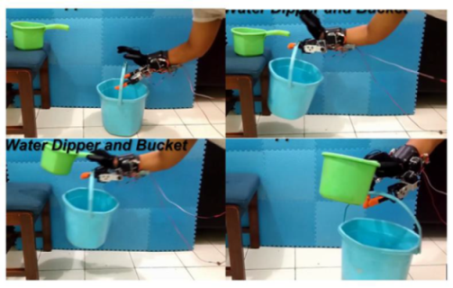
The experimental test with predefined bimanual object manipulations, as shown in Table 5, is repeated eight times. Five bimanual manipulation tasks, such as volleyball, aluminum mug, bottle, and two jars with different sizes, have been trained before. The other bimanual tasks have not been trained yet. Three failure types are identified when the extra robotic fingers and the user’s hand perform the assigned bimanual object manipulation tasks, as summarized in Table 6. It shows the success rate of the eight bimanual tasks carried out using the right hand and extra fingers. The highest success rate is achieved when the robot takes and lifts the dipper and bucket simultaneously because it is easy to perform. Bimanual object manipulations on the bottled-water and egg have the lowest success rate, which accounts for 50%. The bottled-water and egg have a smaller size (contact area) compared to the others, making them harder to reach and grasp. Lifting and opening a bottle cap has the lowest success rate, along with grasping an egg. A slip occurs when human fingers have opened and taken away the bottle cap. This slip causes the bottle to loosen from the grip of the extra fingers.
Based on the experimental work, the extra robotic fingers can lift an object with a mass up to 1.4 kg, when the robotic fingertip is used to lift an object from the lower surface of the object. The extra robotic fingers cannot be applied to lift an object weighing more than 400 g when the robotic fingertips touch and grip the object from the right and left side. A slip will occur, and the object will fall from the extra fingers’ grip, although the extra fingers are attached with a latex glove to increase the friction force. To increase the cooperative grasping manipulation between the extra fingers and the user’s fingers for an object with higher mass, when the extra fingers are touching and gripping the object, the human fingers are applied to grasp and lift the object from the upper side. Thus, these extra fingers are not suitable for bimanual object manipulation tasks for a large object with a mass higher than 1.5 kg, because it can cause fatigue in the user’s hand. It is anticipated that the mass of the robotic fingers worn by a user is 650 g, excluding two LiPo batteries and a microcontroller.
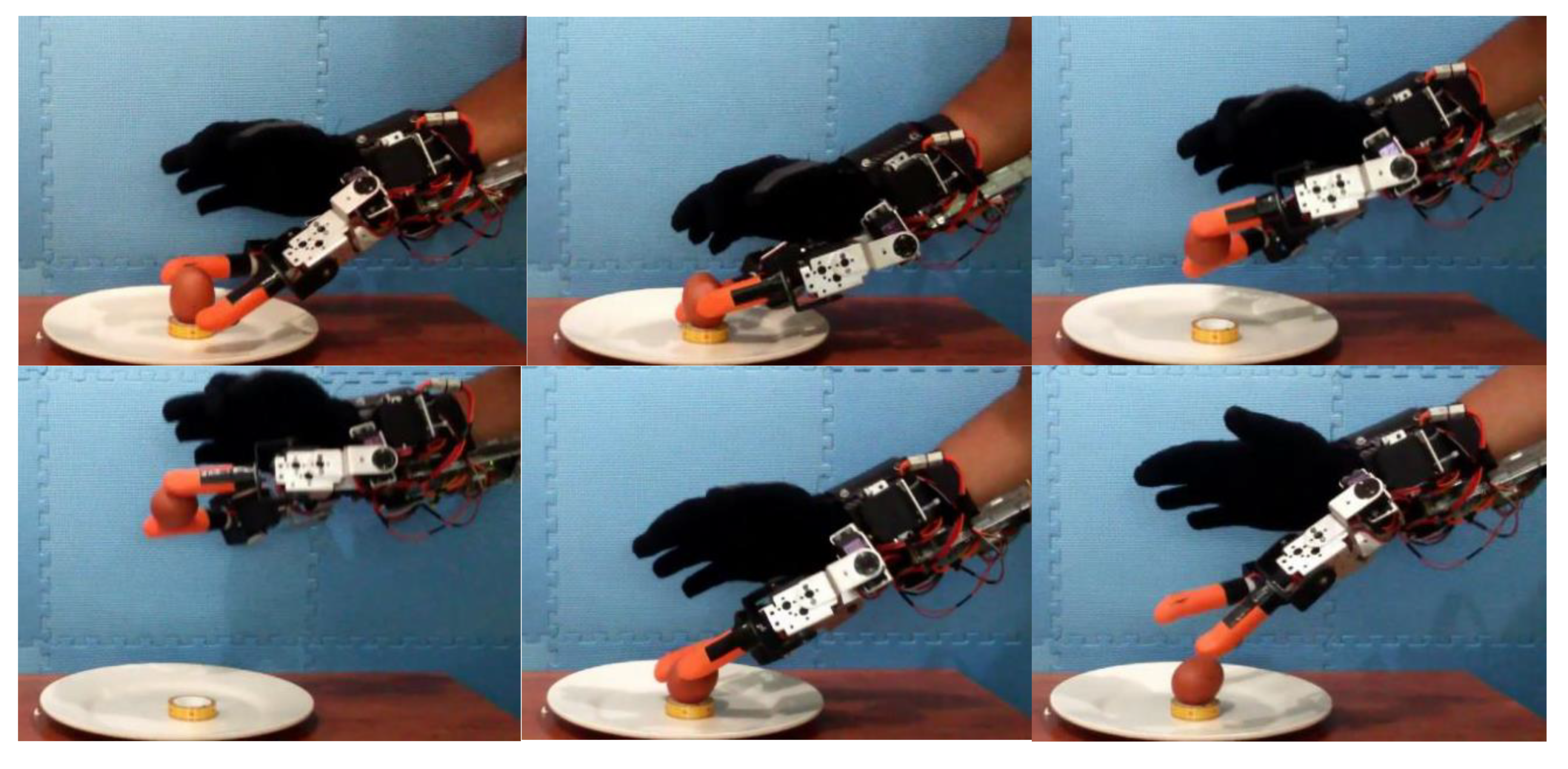
A haptic feedback test is carried out by holding and lifting an egg using two wearable extra robotic fingers, i.e., the RT and RF. The sequence of pictures of the grasping test of an egg can be seen in Figure 12. According to the results of haptic feedback testing, it can be concluded that the testing process of lifting and holding eggs using wearable extra robotic fingers has been successfully carried out without breaking the egg. The egg does not crack or break due to the haptic feedback system released from the FSR signal. The haptic feedback system can work well, because the force that occurs when grasping the egg does not exceed the specified threshold of 9.3 N. A grasping force received by the egg that exceeds 9.3 N will activate the position hold control, so that a holding force of more than 9.3 N will be terminated by position hold control.

5. Conclusions

In this study, a wearable extra robotic finger is successfully developed to assist bimanual tasks that are commonly performed by two normal healthy hands. A data-driven method based on neural network regression is utilized for controlling the coordination between the user's fingers and an extra two fingers, i.e., the RT and RF. The movement of the RT and RF are commanded by bending angle inputs from the user's thumb and index fingers, which are read by the flex sensors. The sensors are attached to a modified glove sensor that can be worn by a user. Various hand gestures are mapped using neural network regression. The third flex sensor is attached to the middle finger to provide a command for position hold of the extra robotic fingers. For the haptic feedback system, two FSRs are attached to the RF and RT.
The trained neural network regression is embedded into Arduino MEGA, to control the robotic finger motion and assist the human fingers in object manipulation, especially in a bimanual task. The developed extra fingers are tested on a user with a normal healthy hand, to assist the human fingers and perform 10 varied bimanual tasks. Based on the experimental results, the proposed extra robotic fingers can successfully provide mechanical assistance in the performance of 10 bimanual tasks. Haptic system test results show that the wearable extra robotic fingers can grasp a fragile object like an egg without breaking it. Based on the promising results for bimanual task assistance, the wearable extra fingers can be a potential assistive device for hemiparetic patients, who have weakness of one entire side of their body. The robot can be attached to the healthy remaining hand of a user who has lost his/her hand function, such as in hemiplegia or hemiparesis. It could enable people who have diminished hand function to perform object manipulation without assistance from others.
For healthy users, the developed extra robotic fingers can provide mechanical assistance for object manipulation in bimanual tasks when this is hard to perform with only one hand. The robot could also improve a user’s work, making it more productive and efficient. Data-driven posture control, based on the neural network, provides more intuitive and dexterous control for extra robotic fingers working collaboratively with the user’s hands.

Author Contributions

J.D.S. conducted data curation, resources, and writing—original draft, and supervision; M.A. carried out conceptualization, methodology, formal analysis, and writing—original draft; (M.M.) M. Munadi performed data curation, writing—review and editing; (M.M.) Muhammad Mutoha conducted software and data curation; W.C. and A.G. provided funding, supervision, and writing—review and editing. All authors have read and agreed to the published version of the manuscript.

Funding

This study was financially partially supported by the Faculty of Engineering, Diponegoro University, Indonesia through Excellent Research Grant, and another part was supported by the authors. The Article Processing Charge (APC) of this paper was supported by Wahyu Caesarendra and Adam Glowacz.

Acknowledgments

Authors would like to thank an undergraduate student at the Department of Mechanical Engineering, Diponegoro University, Zainal Arifin who participated in the manufacturing process of the extra two robotic fingers.

Conflicts of Interest

The authors declare no conflict of interest.

References

  1. Foumani, M.; Smith-Miles, K.; Gunawan, I. Scheduling of two-machine robotic rework cells: In-process, post-process and in-line inspection scenarios. Robot. Auton. Syst. 2017, 91, 210–225. [Google Scholar] [CrossRef]
  2. Foumani, M.; Gunawan, I.; Smith-Miles, K.; Ibrahim, M.Y. Notes on Feasibility and Optimality Conditions of Small-Scale Multifunction Robotic Cell Scheduling Problems with Pickup Restrictions. IEEE T. Ind. Inform. 2015, 11, 821–829. [Google Scholar] [CrossRef] [Green Version]
  3. Koprnický, J.; Najman, P.; Šafka, J. 3D printed bionic prosthetic hands. In Proceedings of the 2017 IEEE International Workshop of Electronics, Control, Measurement, Signals and their Application to Mechatronics (ECMSM), San Sebastian, Spain, 24–26 May 2017; pp. 1–6. [Google Scholar]
  4. Slade, P.; Akhtar, A.; Nguyen, M.; Bretl, T. Tact: Design and performance of an open-source, affordable, myoelectric prosthetic hand. In Proceedings of the 2015 IEEE International Conference on Robotics and Automation (ICRA), Seattle, WA, USA, 26–30 May 2015; pp. 6451–6456. [Google Scholar]
  5. Yoshikawa, M.; Sato, R.; Higashihara, T.; Ogasawara, T.; Kawashima, N. Rehand: Realistic electric prosthetic hand created with a 3D printer. In Proceedings of the 2015 37th Annual International Conference of the IEEE Engineering in Medicine and Biology Society (EMBC), Milan, Italy, 25–29 August 2015; pp. 2470–2473. [Google Scholar]
  6. Ariyanto, M.; Haryadi, G.D.; Ismail, R.; Pakpahan, J.A.; Mustaqim, K.A. A low cost anthropomorphic prosthetic hand using DC micro metal gear motor. In Proceedings of the 2016 3rd International Conference on Information Technology, Computer, and Electrical Engineering (ICITACEE), Semarang, Indonesia, 19–20 October 2016; pp. 42–46. [Google Scholar]
  7. Cipriani, C.; Controzzi, M.; Carrozza, M.C. Objectives, criteria and methods for the design of the SmartHand transradial prosthesis. Robotica 2010, 28, 919–927. [Google Scholar] [CrossRef] [Green Version]
  8. Su, Y.; Fisher, M.H.; Wolczowski, A.; Bell, G.D.; Burn, D.J.; Gao, R.X. Towards an EMG-Controlled Prosthetic Hand Using a 3-D Electromagnetic Positioning System. IEEE Trans. Instrum. Meas. 2007, 56, 178–186. [Google Scholar] [CrossRef]
  9. Jing, X.; Yong, X.; Jiang, Y.; Li, G.; Yokoi, H. Anthropomorphic Prosthetic Hand with Combination of Light Weight and Diversiform Motions. Appl. Sci. 2019, 9, 4203. [Google Scholar] [CrossRef] [Green Version]
  10. Benatti, S.; Milosevic, B.; Farella, E.; Gruppioni, E.; Benini, L. A Prosthetic Hand Body Area Controller Based on Efficient Pattern Recognition Control Strategies. Sensors 2017, 17, 869. [Google Scholar] [CrossRef] [Green Version]
  11. Tavakoli, M.; Batista, R.; Sgrigna, L. The UC Softhand: Light Weight Adaptive Bionic Hand with a Compact Twisted String Actuation System. Actuators 2016, 5, 1. [Google Scholar] [CrossRef] [Green Version]
  12. Au, S.K.; Herr, H.M. Powered ankle-foot prosthesis. IEEE Robot. Autom. Mag. 2008, 15, 52–59. [Google Scholar] [CrossRef]
  13. Martinez- Villalpando, E.C.; Weber, J.; Elliott, G.; Herr, H. Design of an agonist-antagonist active knee prosthesis. In Proceedings of the 2008 2nd IEEE RAS EMBS International Conference on Biomedical Robotics and Biomechatronics, Scottsdale, AZ, USA, 19–22 October 2008; pp. 529–534. [Google Scholar]
  14. Au, S.K.; Weber, J.; Herr, H. Biomechanical Design of a Powered Ankle-Foot Prosthesis. In Proceedings of the 2007 IEEE 10th International Conference on Rehabilitation Robotics, Noordwijk, The Netherlands, 12–15 June 2007; pp. 298–303. [Google Scholar]
  15. Bebionic Hand. Available online: https://www.ottobockus.com/prosthetics/upper-limb-prosthetics/solution-overview/bebionic-hand/ (accessed on 27 February 2020).
  16. Michelangelo Prosthetic Hand. Available online: https://www.ottobockus.com/prosthetics/upper-limb-prosthetics/solution-overview/michelangelo-prosthetic-hand/ (accessed on 20 February 2020).
  17. Open Bionics—Turning Disabilities into Superpowers. Available online: https://openbionics.com/ (accessed on 28 February 2020).
  18. Vincent Systems GmbH. Available online: https://vincentsystems.de/en/ (accessed on 1 March 2020).
  19. HACKberry |3D-Printable Open-Source Bionic Arm. Available online: http://exiii-hackberry.com/ (accessed on 29 March 2020).
  20. Wu, K.-Y.; Su, Y.-Y.; Yu, Y.-L.; Lin, C.-H.; Lan, C.-C. A 5-Degrees-of-Freedom Lightweight Elbow-Wrist Exoskeleton for Forearm Fine-Motion Rehabilitation. IEEE/ASME Trans. Mechatronics 2019, 24, 2684–2695. [Google Scholar] [CrossRef]
  21. Ismail, R.; Ariyanto, M.; Perkasa, I.A.; Adirianto, R.; Putri, F.T.; Glowacz, A.; Caesarendra, W. Soft Elbow Exoskeleton for Upper Limb Assistance Incorporating Dual Motor-Tendon Actuator. Electronics 2019, 8, 1184. [Google Scholar] [CrossRef] [Green Version]
  22. Vitiello, N.; Lenzi, T.; Roccella, S.; De Rossi, S.M.M.; Cattin, E.; Giovacchini, F.; Vecchi, F.; Carrozza, M.C. NEUROExos: A Powered Elbow Exoskeleton for Physical Rehabilitation. IEEE Trans. Robot. 2013, 29, 220–235. [Google Scholar] [CrossRef]
  23. Yun, S.-S.; Kang, B.B.; Cho, K.-J. Exo-Glove PM: An Easily Customizable Modularized Pneumatic Assistive Glove. IEEE Robot. Autom. Lett. 2017, 2, 1725–1732. [Google Scholar] [CrossRef]
  24. Gearhart, C.J.; Varone, B.; Stella, M.H.; BuSha, B.F. An effective 3-fingered augmenting exoskeleton for the human hand. In Proceedings of the 2016 38th Annual International Conference of the IEEE Engineering in Medicine and Biology Society (EMBC), Orlando, FL, USA, 16–20 August 2016; pp. 590–593. [Google Scholar]
  25. Ivanescu, M.; Popescu, N.; Popescu, D.; Channa, A.; Poboroniuc, M. Exoskeleton Hand Control by Fractional Order Models. Sensors 2019, 19, 4608. [Google Scholar] [CrossRef] [Green Version]
  26. Antonellis, P.; Galle, S.; Clercq, D.D.; Malcolm, P. Altering gait variability with an ankle exoskeleton. PLoS ONE 2018, 13, e0205088. [Google Scholar] [CrossRef] [Green Version]
  27. Malcolm, P.; Galle, S.; Derave, W.; De Clercq, D. Bi-articular Knee-Ankle-Foot Exoskeleton Produces Higher Metabolic Cost Reduction than Weight-Matched Mono-articular Exoskeleton. Front. Neurosci. 2018, 12, 69. [Google Scholar] [CrossRef] [Green Version]
  28. Louie, D.R.; Eng, J.J. Powered robotic exoskeletons in post-stroke rehabilitation of gait: A scoping review. J. NeuroEng. Rehabil. 2016, 13, 53. [Google Scholar] [CrossRef] [Green Version]
  29. Jones, C.L.; Wang, F.; Morrison, R.; Sarkar, N.; Kamper, D.G. Design and Development of the Cable Actuated Finger Exoskeleton for Hand Rehabilitation Following Stroke. IEEE/ASME Trans. Mechatronics 2014, 19, 131–140. [Google Scholar] [CrossRef]
  30. Treers, L.; Lo, R.; Cheung, M.; Guy, A.; Guggenheim, J.; Parietti, F.; Asada, H. Design and Control of Lightweight Supernumerary Robotic Limbs for Sitting/Standing Assistance. In Proceedings of the 2016 International Symposium on Experimental Robotics, Tokyo, Japan, 3–6 October 2016; Kulić, D., Nakamura, Y., Khatib, O., Venture, G., Eds.; Springer International Publishing: Cham, Switzerland, 2017; pp. 299–308. [Google Scholar]
  31. Parietti, F.; Chan, K.C.; Hunter, B.; Asada, H.H. Design and control of Supernumerary Robotic Limbs for balance augmentation. In Proceedings of the 2015 IEEE International Conference on Robotics and Automation (ICRA), Seattle, WA, USA, 26–30 May 2015; pp. 5010–5017. [Google Scholar]
  32. Parietti, F.; Asada, H.H. Supernumerary Robotic Limbs for aircraft fuselage assembly: Body stabilization and guidance by bracing. In Proceedings of the 2014 IEEE International Conference on Robotics and Automation (ICRA), Hong Kong, China, 31 May–7 June 2014; pp. 1176–1183. [Google Scholar]
  33. Sasaki, T.; Saraiji, M.Y.; Fernando, C.L.; Minamizawa, K.; Inami, M. MetaLimbs: Multiple arms interaction metamorphism. In Proceedings of the ACM SIGGRAPH 2017 Emerging Technologies, SIGGRAPH 2017, Los Angeles, CA, USA, 30 July–3 August 2017; Association for Computing Machinery, Inc.: New York, NY, USA, 2017; p. 16. [Google Scholar]
  34. Llorens-Bonilla, B.; Asada, H.H. Control and Coordination of Supernumerary Robotic Limbs Based on Human Motion Detection and Task Petri Net Model; American Society of Mechanical Engineers Digital Collection: New York, NY, USA, 2014. [Google Scholar]
  35. Wu, F.Y.; Asada, H. Bio-Artificial Synergies for Grasp Posture Control of Supernumerary Robotic Fingers. In Proceedings of the in Robotics: Science and Systems X, University of California, Berkeley, CA, USA, 12–16 July 2014. [Google Scholar]
  36. Wu, F.Y.; Asada, H.H. Implicit and Intuitive Grasp Posture Control for Wearable Robotic Fingers: A Data-Driven Method Using Partial Least Squares. IEEE Trans. Robot. 2016, 32, 176–186. [Google Scholar] [CrossRef]
  37. Wu, F.Y.; Asada, H.H. “Hold-and-manipulate” with a single hand being assisted by wearable extra fingers. In Proceedings of the 2015 IEEE International Conference on Robotics and Automation (ICRA), Seattle, WA, USA, 26–30 May 2015; pp. 6205–6212. [Google Scholar]
  38. Ort, T.; Wu, F.; Hensel, N.C.; Asada, H.H. Supernumerary Robotic Fingers as a Therapeutic Device for Hemiparetic Patients; American Society of Mechanical Engineers Digital Collection: New York, NY, USA, 2016. [Google Scholar]
  39. Segura Meraz, N.; Sobajima, M.; Aoyama, T.; Hasegawa, Y. Modification of body schema by use of extra robotic thumb. ROBOMECH J. 2018, 5, 3. [Google Scholar] [CrossRef] [Green Version]
  40. Zhu, Y.; Ito, T.; Aoyama, T.; Hasegawa, Y. Development of sense of self-location based on somatosensory feedback from finger tips for extra robotic thumb control. ROBOMECH J. 2019, 6, 7. [Google Scholar] [CrossRef]
  41. Hussain, I.; Spagnoletti, G.; Salvietti, G.; Prattichizzo, D. An EMG Interface for the Control of Motion and Compliance of a Supernumerary Robotic Finger. Front. Neurorobot. 2016, 10, 18. [Google Scholar] [CrossRef] [PubMed] [Green Version]
  42. Hussain, I.; Salvietti, G.; Spagnoletti, G.; Prattichizzo, D. The Soft-SixthFinger: A Wearable EMG Controlled Robotic Extra-Finger for Grasp Compensation in Chronic Stroke Patients. IEEE Robot. Autom. Lett. 2016, 1, 1000–1006. [Google Scholar] [CrossRef] [Green Version]
  43. Prattichizzo, D.; Malvezzi, M.; Hussain, I.; Salvietti, G. The Sixth-Finger: A modular extra-finger to enhance human hand capabilities. In Proceedings of the 23rd IEEE International Symposium on Robot and Human Interactive Communication, Edinburgh, UK, 25–29 August 2014; pp. 993–998. [Google Scholar]
  44. Salvietti, G.; Hussain, I.; Cioncoloni, D.; Taddei, S.; Rossi, S.; Prattichizzo, D. Compensating Hand Function in Chronic Stroke Patients Through the Robotic Sixth Finger. IEEE Trans. Neural Syst. Rehabil. Eng. 2017, 25, 142–150. [Google Scholar] [CrossRef] [PubMed]
  45. Hussain, I.; Salvietti, G.; Malvezzi, M.; Prattichizzo, D. Design guidelines for a wearable robotic extra-finger. In Proceedings of the 2015 IEEE 1st International Forum on Research and Technologies for Society and Industry Leveraging a better tomorrow (RTSI), Torino, Italy, 16–18 September 2015; pp. 54–60. [Google Scholar]
  46. Ariyanto, M.; Ismail, R.; Nurmiranto, A.; Caesarendra, W.; Franke, J. Development of a low cost anthropomorphic robotic hand driven by modified glove sensor and integrated with 3D animation. In Proceedings of the 2016 IEEE EMBS Conference on Biomedical Engineering and Sciences (IECBES), Kuala Lumpur, Malaysia, 4–7 December 2016; pp. 341–346. [Google Scholar]
  47. Ariyanto, M.; Ismail, R.; Setiawan, J.D.; Arifin, Z. Development of low cost supernumerary robotic fingers as an assistive device. In Proceedings of the 2017 4th International Conference on Electrical Engineering, Computer Science and Informatics (EECSI), Yogyakarta, Indonesia, 19–21 September 2017; pp. 1–6. [Google Scholar]
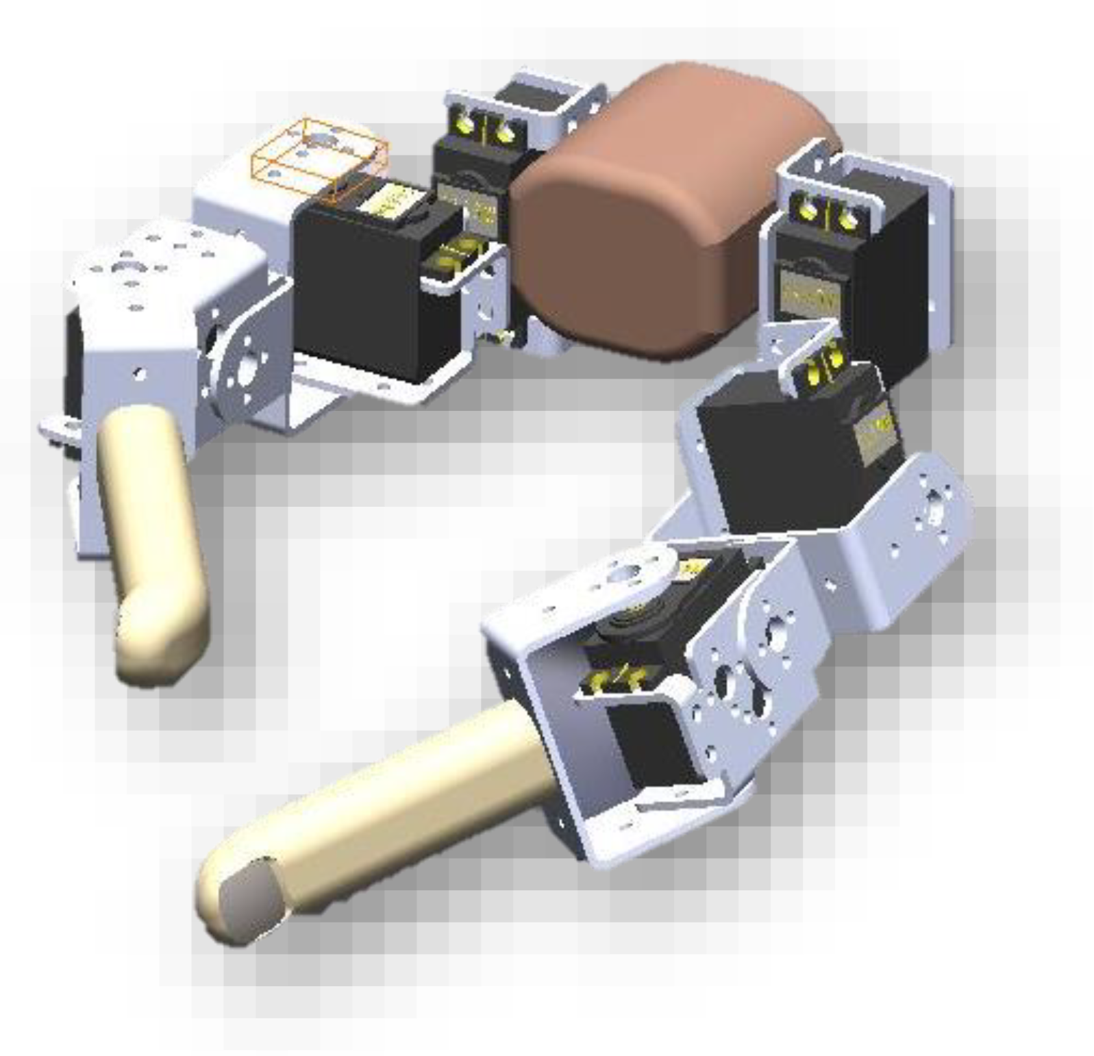
Figure 1. 3D SolidWorks design of extra robotic fingers.
Electronics 09 00905 g001
Figure 2. Developed extra robotic fingers for assisting bimanual task.
Electronics 09 00905 g002
Figure 3. Developed glove sensor for extra robotic finger input.
Electronics 09 00905 g003
Figure 4. Data-driven posture map from flex sensor to servo motor-commanded angles: (a) Robotic thumb; (b) Robotic finger.
Electronics 09 00905 g004
Figure 5. Performance of neural network regression during training: (a) Mean squared error; (b) Sum squared error.
Electronics 09 00905 g005
Figure 6. Implemented neural network regression block diagram for posture control coordination.
Electronics 09 00905 g006
Figure 7. Implemented control algorithm block diagram for posture control coordination.
Electronics 09 00905 g007
Figure 8. Overall embedded grasp posture control blocks for extra robotic fingers.
Electronics 09 00905 g008
Figure 9. FSR sensors calibration on RT and RF.
Electronics 09 00905 g009
Figure 10. neural network regression input and output.
Electronics 09 00905 g010
Figure 11. Fingertip trajectories: (a) RT; (b) RF.
Electronics 09 00905 g011
Figure 12. Sequence images of haptic performance test.
Electronics 09 00905 g012
Table 1. Denavit–Hartenberg (DH) parameters on the extra robotic fingers.
Linkai (mm)αi (Degree)di (mm)θi (Degree)
12590°0θ1
27590°0θ2
31160θ3
42590°0θ4
5750θ5
61160θ6
Table 2. Utilized neural network regression parameters.
NN ParametersValue
Model Feedforward neural network
Number of neurons in hidden layer5
Number of neurons in output layer6
Divide ParameterRandom
Ratio of Training70%
Ratio of Validation15%
Ratio of Testing15%
Training AlgorithmLevenberg-Marquardt backpropagation
Maximum Epoch1000
Performance Goal0.001
Error performanceMean squared error (MSE)
Sum squared error (SSE)
Transfer function of hidden layerLinear transfer function
Transfer function of output layerLinear transfer function
Table 3. MSE and SSE results during training.
Error PerformanceR
TrainingValidationTestOverall
MSE0.99970.99990.99940.9997
SSE0.99970.99980.99930.9995
Table 4. Truth table of position hold control.
x3 > ThresholdF1 > ThresholdF2 > ThresholdPosition Hold Control
000inactive
001active
010active
011active
100active
101active
110active
111active
Table 5. Bimanual manipulation assist test with the developed extra robotic fingers.
Object ManipulationBimanual Task Results
Lifting and stirring water and sugar in an aluminum mug Electronics 09 00905 i001
Grasping and lifting volleyball Electronics 09 00905 i002
Lifting and opening a bottle cap Electronics 09 00905 i003
Unplugging the AC power plug from the extension cord reel Electronics 09 00905 i004
Opening first jar lid Electronics 09 00905 i005
Opening second jar lid Electronics 09 00905 i006
Tightening a bolt to electronic components Electronics 09 00905 i007
Operating a 6" tablet Electronics 09 00905 i008
Taking and lifting the dipper and bucket simultaneously Electronics 09 00905 i009
Operating an 8" tablet Electronics 09 00905 i010
Table 6. Experimental results of bimanual task assistance.
Object ManipulationSuccess Failure
Missed ObjectObject SlippedExtra Fingers Obstruct the Grasp
Aluminum mug5/81/81/81/8
Volleyball6/81/80/81/8
Bottled-water4/82/82/80/8
Extension cord reel7/80/80/81/8
First jar lid5/82/80/81/8
Second jar lid6/81/81/80/8
Tighten a bolt5/82/80/81/8
Dipper and bucket8/80/80/80/8
6” tablet7/81/80/80/8
8” tablet8/80/80/80/8
Egg4/83/81/80/8