Article

Optical Transmission of an Analog TV-Signal Coded at 2.24 GHz and Its Distribution by Using a Radiating Cable

by
Ana Gabriela Correa-Mena
1,2,
Jorge Alberto Seseña-Osorio
1,
Melissa Eugenia Diago-Mosquera
3,
Alejandro Aragón-Zavala
3 and
Ignacio Enrique Zaldívar-Huerta
1,*
1
Departamento de Electrónica, Instituto Nacional de Astrofísica, Óptica y Electrónica, Calle Luis Enrique Erro No.1, Tonantzintla, Puebla 72840, Mexico
2
Departamento de Ciencias de la Computación y Electrónica, Universidad Técnica Particular de Loja, San Cayetano Alto, Loja 1101608, Ecuador
3
Escuela de Ingeniería y Ciencias, Tecnológico de Monterrey, Av. Epigmenio González 500, Fracc. San Pablo Querétaro 76130, Mexico
*
Author to whom correspondence should be addressed.
Electronics 2020, 9(6), 917; https://doi.org/10.3390/electronics9060917
Submission received: 7 May 2020 / Revised: 20 May 2020 / Accepted: 25 May 2020 / Published: 1 June 2020
(This article belongs to the Section Microelectronics)

Abstract

:
In this work, an alternative technology to extend wireless coverage beyond the conventional methods of providing radio propagation coverage is presented. The use of a radiating cable is proposed for difficult-to-reach areas. In this regard, an indoor radiating cable is successfully employed for the distribution of an analog electric signal in a fiber-radio scheme using a microwave photonic filter. A filtered microwave band-pass window located at 2.24 GHz is used as an electrical carrier to transmit an analog TV-signal of 67.25 MHz over an optical link of 25.28 km. Measurements are carried out in an indoor environment. Experimental results demonstrate that the recovered signal is of good quality in each measurement location, exhibiting on average a signal-to-noise-ratio (SNR) of around 31.60 dB.

1. Introduction

The widespread use of mobile communications with broadband applications has increased in recent years. This trend has led to an increase in the demand for the delivery of data and video services to a large number of users in optical and wireless access services, and a greater concentration of mobile devices inside buildings, e.g., university campus, shopping centers, airports, and underground environments. Considering the challenges of this explosive growth, wireless optical communications (WOC) are a good option to provide large bandwidth for users under these scenarios [1]. WOC offers a bundle of advantages, e.g., the electromagnetic spectrum is not licensed in the optical band, thus spectrum licensing fees are avoided and system cost can be reduced. Optical radiation in the infrared or visible range is easily contained by opaque boundaries. As a result, interference between adjacent devices can be minimized easily and economically. Although this contributes to the security of wireless optical links and reduces interference, it also impacts rather stringently on the mobility of such devices [2]. Wireless optical links transmit information by using an optoelectronic light modulator and allow its distribution through fiber optics to users located in indoor environments. In order to provide optimal coverage levels inside buildings, usually, the final distribution in a WOC is implemented through omnidirectional antennas placed at strategic locations. The deployment of these antennas, mainly to address hot-spot areas, may not be possible in outage zones, due to the impossibility of their installation in specific regions inside venues, their radiation pattern characteristics, and the maximum transmit power limitations. Therefore, radiating cables have been demonstrated to be a viable option to overcome such constraints, since their coverage footprint is uniform and can increase the signal strength in indoor environments [3,4,5,6].
A radiating cable is a slotted coaxial cable run along specific indoor areas, which emits and receives radio waves, operating as an extended antenna. The cable is leaky, i.e., it has gaps or slots in its outer conductor to allow the radio signal to leak into or out of the cable along its entire length. Because of this leakage of signal, line amplifiers are required to be inserted at regular intervals, typically every 350 meters to 500 meters, to enhance the signal back up to acceptable levels [7]. On the other hand, an inherent feature of Microwave Photonic Filters (MPFs) is that microwave signals are directly processed in the optical domain, exploiting advantages inherent to photonics such as low loss, high bandwidth, immunity to electromagnetic interference, and tunability [8], making them a very interesting choice compared to conventional electrical filters. The factors previously described, together with the increasing demand for multiple communications applications with a great amount of associated information, justify the introduction of MPFs into the access optical networks [9]. Furthermore, a comparison between our proposed fiber-radio scheme with the WOC’s works reported in the last few years is presented in Table 1. The parameters considered are the frequency of the electrical carrier, the signal-to-noise-ratio of the recovered signal (SNRRX), the fiber length, and the transmision and reception of the signal by using radiating cable and antennas, respectively.
Considering the main goal of this work is to demonstrate the feasibility of distribution by a radiating cable of an analog TV-signal in a fiber-radio scheme inside a building, a band-pass window at 2.24 GHz generated by a microwave photonic filter is used to code on the analog TV signal of 67.25 MHz. This TV signal is transmitted over an optical link of 25.28 km for its further distribution by a radiating cable of 5.50 m length. The novelty of this work resides in the integration of the radiated cable technique with the fiber scheme to transmit and distribute electrical signals, using optoelectronic techniques and its further radio distribution in an indoor environment. Thus, this fiber-radio scheme could be used as part of a wireless optical communication system.
The paper is organized as follows: Section 2 provides the basic theory of the MPF operation principle. Moreover, the experimental frequency response of the characterized MPF is presented. The experimental procedure for the transmission, distribution, and recovery of the analog TV-signal is described in Section 3. Finally, the main conclusions are included in Section 4.

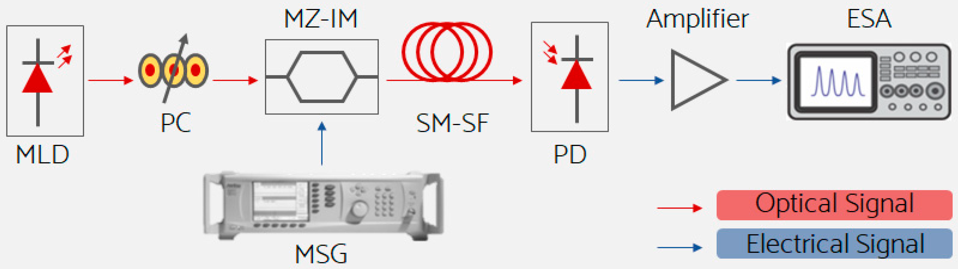
2. Microwave Photonic Filter

This section is divided in two subsections. First, the main equations that describe the frequency response of the MPF are detailed. In the second subsection, the MPF is characterized to obtain the electrical parameters of the filtered band-pass windows that will be used as electrical carriers.

2.1. Principle of Operation

Previously, the authors of [16] reported the use of a basic architecture of MPFs that consist of four basic components: an optical source, a modulator, a fiber coil, and a photodetector. The frequency response of this MPF is constituted of a series of microwave band-pass windows that depend on the fiber chromatic dispersion, fiber length, and Fourier transform of the spectral density of the optical source. In particular, when a Multimode Laser Diode (MLD) is used as an optical source, the theoretical center frequency of the nth filtered band-pass window is computed as [16]
f n = n ( 1 D L δ λ )
where n is a positive integer (n = 1, 2, …), δλ (nm) is the Free Spectral Range (FSR) between the modes of the MLD, and L (km) and D (ps/nm·km) are the length and the chromatic dispersion of the Single Mode-Standard Fibre (SM-SF), respectively. The bandwidth at −3dB of the nth filtered band-pass window is obtained as [16]
Δ f b p = 4 ln ( 2 ) π D L Δ λ
where Δλ (nm) is the spectral width of the optical source.

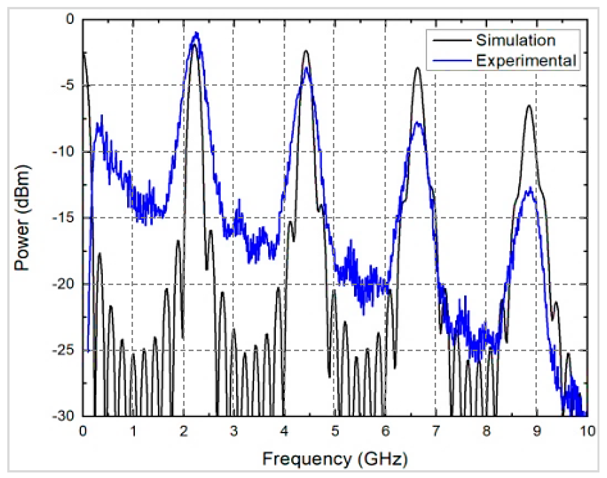
2.2. Experimental MPF Characterization

Figure 1 shows the microwave photonic filter scheme that is characterized. The MPF is composed of an optical source MLD, a Polarization Controller (PC), a Mach–Zehnder Intensity Modulator (MZ-IM), a Microwave Signal Generator (MSG), an SM-SF, and a Photo Detector (PD). The Electrical Spectrum Analyzer (ESA) is used to measure the frequency response of the system. The MLD is driven at 25 °C by a temperature controller and operated with a well-stabilized injection current of 20 mA. Under this condition, its optical characteristics are central wavelength λ0 = 1547.2 nm, Δλ = 7.31 nm, and δλ = 1.1 nm.
The light issued of the MLD (Thorlabs, LPS-1550-FC) passes through the PC. Subsequently, it is injected to the MZ-IM (MXAN-LN-20, insertion loss of 2.7 dB, operating wavelength of 1530 nm to 1580 nm) where it is intensity-modulated by an RF signal supplied by the MSG in the frequency range of 0.01 GHz to 10 GHz at an electrical power of 5 dBm. The modulated light travels along 25.28 km of the SM-SF (α = 0.2 dB/km, D = 15.81 ps/nm·km @ 1500 nm). At the output of the fiber, the PD (DR-125G-A, 30 kHz to 12.5 GHz) converts the light to its corresponding photo-current. This experiment is carried out at the maximum PD frequency of 10 GHz. Finally, the electrical signal at the PD’s output is amplified and connected to the ESA (Anritsu, MG3692, frequency range 0.01 GHz to 20 GHz) to measure the MPF’s frequency response. This experimental frequency response is formed by four microwave band-pass windows, as shown in the blue curve of Figure 2. The center frequency of each filtered band-pass window is f1 = 2.24 GHz, f2 = 4.40 GHz, f3 = 6.62 GHz, and f4 = 8.86 GHz. On the same graph, the black curve corresponds to the theoretical frequency response obtained by using the VPIphotonics software [17], and it is in good concordance with the experimental response. Additionally, the increase in attenuation observed in the frequency response plot as frequency increases is justified by the influence of the envelope of the source power spectrum, as was demonstrated by the authors of [13]. The interested reader can see this reference for a detailed explanation.
Table 2 summarizes the electrical characteristics of the filtered band-pass windows. Relevant parameters shown are: the center frequency and bandwidth of each band-pass window computed by using Equations (1) and (2), respectively; the Signal-to-Noise-Ratio (SNR) and the related error percentage between the theoretical and experimental center frequency fn are calculated as
% error , f n = | f n , theoretical f n , experimental | f n , theoretical × 100 %
Additionally, from Table 2 we notice that the average of the electrical bandwidth exhibited by the filtered bandpass windows is around 350 MHz. This bandwidth is enough to code an analog TV-signal of 6 MHz on any filtered band-pass [18]. In this work, the first microwave band-pass window of 2.24 GHz is selected as an electrical carrier. However, potentially the other band-pass windows could be used as electrical carriers.

3. Experimental Results

For a better understanding of the results, this section is divided in three subsections. First, the experimental setup for the transmission of the analog TV-signal by radiating cable is presented. The characteristics of the indoor environment as well as the position of the omnidirectional antenna that will receive the signal transmitted by the radiating cable are described next. Finally, the measured electrical spectrum for the transmitted and recovered analog TV-signal are shown.

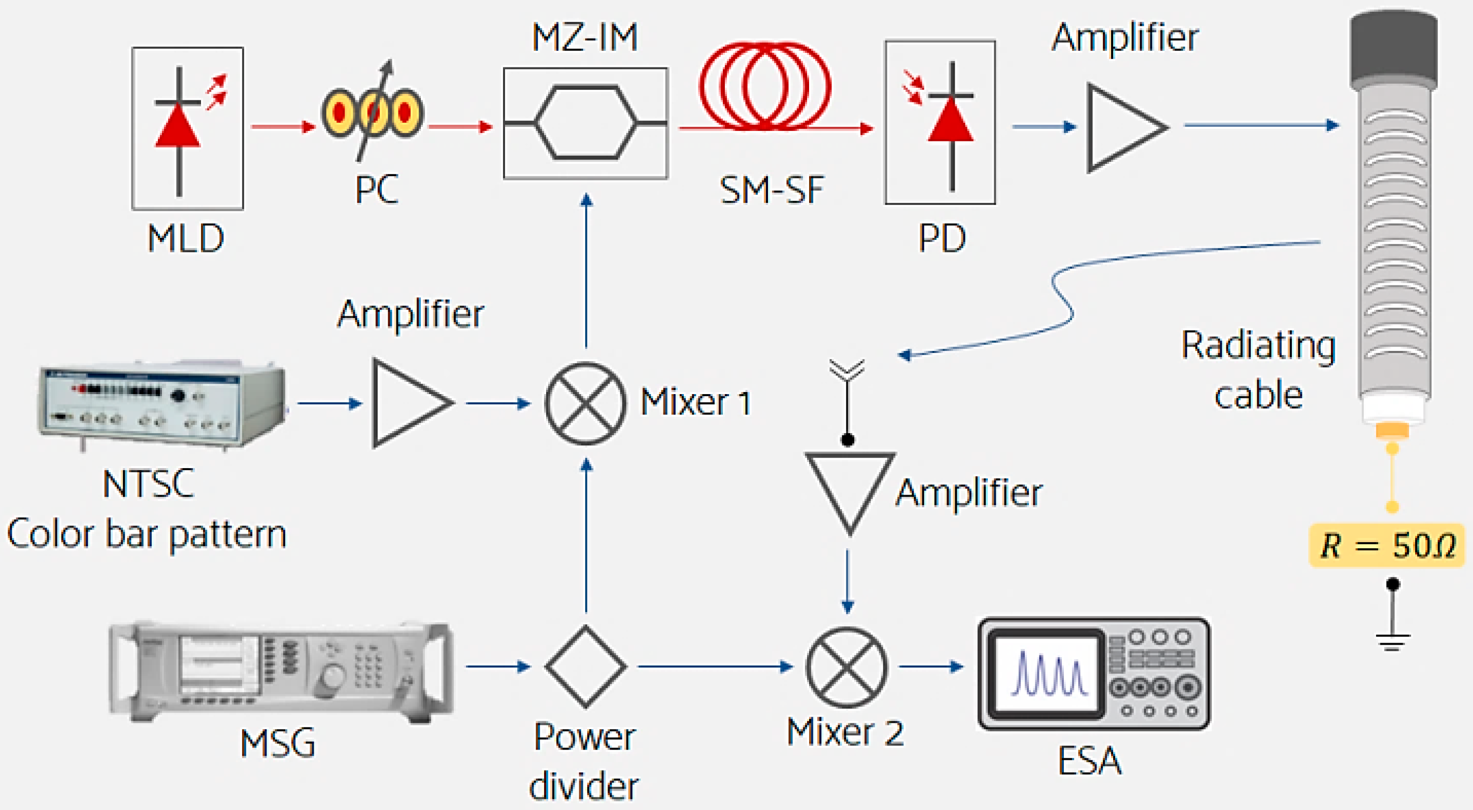
3.1. Experimental Setup

Figure 3 depicts the proposed experimental setup for the transmission of the analog TV-signal using radiating cable. This setup is based on the scheme of Figure 2; in order to have the complete fiber-radio scheme, some devices are added. Hence, the light issued by the MLD passes through the PC and is injected to the MZ-IM. The MSG provides the RF signal of 2.24 GHz at 15 dBm that is mixed (Mixer 1) with the amplified TV-signal of 67.25 MHz (Channel 4) delivered by the NTSC (BK Precision, Model 1249B) generator (National Television System Committee) [18]. The resulting electrical signal used to modulate the light given by the MLD is connected to the RF port of the MZ-IM. The modulated optical signal is launched into the coil SM-SF of 25.28 km. Afterward, the optical signal travels 25.28 km, and it is injected to the PD that converts the optical to the electrical signal. This final signal is amplified and matched to 5.50 m of the radiating cable (RADIAFLEX® model RCF 12–50 J, manufactured by Radio Frequency Systems, maximum operating frequency 6 GHz) [19]. The Leaky Coaxial Cable (LCX) is terminated with a matched 50 Ω load to avoid any unwanted reflections. On the other hand, the receiving stage is composed of an omnidirectional antenna (Kathrein, gain G = 2 dBi). The electrical signal captured by the antenna is amplified and plugged to Mixer 2 in order to suppress the carrier signal of 2.24 GHz and recover the TV-signal. The quality of the recovered TV-signal is measured by the ESA.

3.2. Measurement Locations Map

Figure 4 corresponds to the architectonic layout of the laboratory where the electrical measurements were carried out. According to the bibliography [20], it is very important to indicate the materials used in the construction of the laboratory, objects, and distribution of furniture placed at the interior to observe the effects of absorption, dispersion, and fading of the signal. The measurements of the analog TV-signal transmission by using the radiating cable are made inside the INAOE’s optical communications lab. The walls and floor are made with drywall and vinyl tile, respectively. The ceiling is constructed of steel decks and metallic beams. It is 4 m high and has a suspended false ceiling at 2.60 m. The radiating cable is installed over the false ceiling, and it is laid along one path of 5.50 m. Inside the laboratory, there are optical and electrical equipment, computers, desks, and chairs. Moreover, the points in red show the position where the omnidirectional antenna is installed to receive the TV signal delivered by the radiating cable. These measuring locations (ml) are labeled from 1 to 6. Between each, there is 1 m of distance to cover all the available lab’s area.

3.3. Results

The technical criteria to validate the feasibility of the distribution of an analog TV-signal by using a radiating cable are focused on evaluating the SNRRX of the recovered signal for each ml. Figure 5a,b shows the measured electrical spectrum for the transmitted as well as the recovered analog TV-signal of 67.25 MHz. The measured average of the SNR value for the transmitted and recovered analog TV-signal was 61.95 dB and 31.60 dB, respectively. The obtained SNRRX values are in good agreement with the works reported in references [3,16]. The results demonstrate that the recovered signal presents a good quality in each ml, highlighting that the best location is in ml4 with a SNRRX of 36.53 dB and a received electrical power of −22 dBm, approximately.

4. Conclusions

A fiber-radio scheme using a microwave photonic filter and a radiating cable to distribute an analog TV-signal was successfully demonstrated. The novelty of this work resides in the integration of the radiated cable technique with the fiber scheme to transmit information using optoelectronic techniques and its further radio distribution in an indoor environment. In particular, the analog TV-signal is coded on an electrical carrier at 2.24 GHz, and it is transmitted through an optical link of 25.28 km for its further distribution through 5.50 m of radiating cable. In this experiment, the location of the bandpass window at 2.24 GHz present in the frequency response of the MPF is fixed at a particular optical fiber length of 25.28 km. However, the versatility of the proposed scheme resides in the fact that the center frequency of the nth filtered band-pass windows could be tuned to a particular value, as is indicated in Equation (1). On the other hand, in order to emulate the indoor environment, the distribution of the TV-signal was carried out inside the INAOE’s optical communications lab. Experimental measurements have shown that the recovered TV-signal in all the measuring locations have acceptable SNR values (31.60 dB on average). The transmit power level within the experimental frequency range satisfies the IEEE C95.1-1999 Standard Safety Levels for preventing harmful effects in humans exposed to electromagnetic fields in the 3 kHz to 300 GHz frequency range [21]. Furthermore, this fiber-radio system operating at the ISM frequency band (2.4 GHz) is characterized by its short coverage range and low power, guarantying noninterference with other equipment, especially, medical equipment [22]. Finally, it is important to remark that we decided to transmit and distribute an analog TV-signal because in Mexico the analog shutdown occurred some years ago. However, this fiber-radio scheme could be used to transmit different IP services, such as high definition television (HDTV), video gaming, and voice.

Author Contributions

Conceptualization and methodology, J.A.S.-O., A.G.C.-M., and I.E.Z.-H.; formal analysis, J.A.S.-O., A.G.C.-M., M.E.D.-M., A.A.-Z., and I.E.Z.-H.; investigation, J.A.S.-O. and A.G.C.-M.; writing—original draft preparation, A.G.C.-M., A.A.-Z., and I.E.Z.-H.; writing—review and editing, M.E.D.-M., A.A.-Z., and I.E.Z.-H.; visualization, M.E.D.-M.; supervision, A.A.-Z. and I.E.Z.-H.; project administration, A.A.-Z and I.E.Z.-H.; funding acquisition, I.E.Z.-H. All authors have read and agreed to the published version of the manuscript.

Funding

This research did not receive external funding.

Acknowledgments

A. G. Correa-Mena, J. A. Seseña-Osorio, and M. E. Diago-Mosquera wish to thank CONACyT for the student scholarships number 335148, 204357, and 746015, respectively.

Conflicts of Interest

The authors declare no conflict of interest.

References

  1. Zhang, T.; Feng, J.; Xiao, J.; Tang, J. The Analysis of the Communication Distance in Wireless Optical Communications for Trains. In Proceedings of the 3rd International Conference on Electrical and Information Technologies for Rail Transportation (EITRT) 2017; Springer Science and Business Media: Berlin/Heidelberg, Germany, 2018; Volume 482, pp. 865–870. [Google Scholar]
  2. Hranilovic, S. Wireless Optical Communication Systems; Springer: Berlin/Heidelberg, Germany, 2005. [Google Scholar]
  3. Correa Mena, A.G.; Zaldívar Huerta, I.E.; Seseña Osorio, J.; Aragón Zavala, A.; Abril García, J.H.; García Juárez, A. Experimental optical transmission of electrical signals in the frequency range of 0.9–2.3 GHz and its distribution by using a radiating cable. Environments 2016, 2, 3. [Google Scholar]
  4. Jiang, J.; Wang, L.; Wang, G. Leaky coaxial cable for near-field UHF RFID applications. In Proceedings of the 2017 Sixth Asia-Pacific Conference on Antennas and Propagation (APCAP), Xi’an, China, 16–19 October 2017; pp. 1–3. [Google Scholar]
  5. Siddiqui, Z.; Sonkki, M.; Tuhkala, M.; Myllymäki, S. Sinusoidally Modulated Reactance Surface Loaded Leaky Coaxial Cable. In Proceedings of the 13th European Conference on Antennas and Propagation (EuCAP), Krakow, Poland, 31 March–5 April 2019; pp. 1–4. [Google Scholar]
  6. Siddiqui, Z.; Sonkki, M.; Tuhkala, M.; Myllymaki, S. Leaky Coaxial Cable with Enhanced Radiation Performance for Indoor Communication Systems. In Proceedings of the 2019 16th International Symposium on Wireless Communication Systems (ISWCS), Oulu, Finland, 27–30 August 2019; pp. 724–727. [Google Scholar]
  7. Kamruzzaman, S.M.; Fernando, X.; Jaseemuddin, M.; Farjow, W. Reliable Communication Network for Emergency Response and Disaster Management in Underground Mines. In Handbook of Research on Accounting and Financial Studies; IGI Global: Hershey, PA, USA, 2018; pp. 41–85. [Google Scholar]
  8. Capmany, J.; Ortega, B.; Pastor, D. A tutorial on microwave photonic filters. J. Light. Technol. 2006, 24, 201–229. [Google Scholar] [CrossRef]
  9. Capmany, J.; Mora, J.; Gasulla, I.; Sancho, J.; Lloret, J.; Sales, S. Microwave Photonic Signal Processing. J. Light. Technol. 2013, 31, 571–586. [Google Scholar] [CrossRef]
  10. Chung, H.S.; Chang, S.H.; Park, J.D.; Chu, M.-J.; Kim, K. Transmission of Multiple HD-TV Signals Over a Wired/Wireless Line Millimeter-Wave Link With 60 GHz. J. Light. Technol. 2007, 25, 3413–3418. [Google Scholar] [CrossRef]
  11. Dudley, S.; Quinlan, T.; Walker, S. Ultrabroadband Wireless–Optical Transmission Links Using Axial Slot Leaky Feeders and Optical Fiber for Underground Transport Topologies. IEEE Trans. Veh. Technol. 2008, 57, 3471–3476. [Google Scholar] [CrossRef]
  12. Zaldívar-Huerta, I.E.; García-Juárez, A.; Pérez-Montaña, D.; Nava, P.H.; Vera-Marquina, A. Proposal and performance evaluation of a Fiber-To-The-Antenna system for video distribution operating in the S-band. Opt. Laser Technol. 2015, 71, 89–94. [Google Scholar] [CrossRef] [Green Version]
  13. Icedo-Navarro, J.A.; Rodríguez, R.E.T.; García-Juárez, A.; Noriega-Luna, J.R.; Correa-Mena, A.G.; González-Mondragón, L.A.; Zaldivar-Huerta, I.E. Transmission system for digital TV-signal distribution through a passive optical network in the microwave S-band. In Proceedings of the 2017 IEEE 9th Latin-American Conference on Communications (LATINCOM), Guatemala City, Guatemala, 8–10 November 2017; pp. 1–6. [Google Scholar]
  14. Habib, U.; Steeg, M.; Stohr, A.; Gomes, N.J. Radio-over-Fiber-supported Millimeter-wave Multiuser Transmission with Low-Complexity Antenna Units. In Proceedings of the 2018 International Topical Meeting on Microwave Photonics (MWP), Toulouse, France, 22–25 October 2018; pp. 1–4. [Google Scholar] [CrossRef] [Green Version]
  15. Habib, U.; Aighobahi, A.E.; Quinlan, T.; Walker, S.D.; Gomes, N.J. Analog Radio-Over-Fiber Supported Increased RAU Spacing for 60 GHz Distributed MIMO Employing Spatial Diversity and Multiplexing. J. Light. Technol. 2018, 36, 4354–4360. [Google Scholar] [CrossRef]
  16. González-Mondragón, L.A.; Quintero-Rodríguez, L.J.; García-Juárez, A.; Vera-Marquina, A.; Zaldívar-Huerta, I.E. Multiple passband microwave photonic filter with adjustable bandwidth. Opt. Laser Technol. 2020, 126, 106133. [Google Scholar] [CrossRef]
  17. SaM Solutions company VPIphotonics: Simulation Software and Design Services. Available online: https://www.vpiphotonics.com/index.php (accessed on 10 March 2020).
  18. Ovadia, S. Broadband Cable TV Access Networks, 1st ed; Prentice Hall: New Jersey, NJ, USA, 2001. [Google Scholar]
  19. RCF, R.F.S. PRODUCT DATASHEET RCF12-50JFN. 2018. Available online: http://products.rfsworld.com//WebSearchECat/datasheets/pdf/cache/RCF12-50JFN.pdf (accessed on 18 March 2020).
  20. Sesena-Osorio, J.A.; Aragón-Zavala, A.; Zaldívar-Huerta, I.E.; Castanon, G. INDOOR PROPAGATION MODELING FOR RADIATING CABLE SYSTEMS IN THE FREQUENCY RANGE OF 900-2500 MHZ. Prog. Electromagn. Res. B 2013, 47, 241–262. [Google Scholar] [CrossRef] [Green Version]
  21. IEEE Standard for Safety Levels with Respect to Human Exposure to Radio Frequency Electromagnetic Fields, 3 kHz to 300 GHz 2008. Available online: https://standards.ieee.org/standard/C95_1-1991.html (accessed on 19 May 2020).
  22. Qaddus, A. An Evaluation of 2.4 GHz and 5 GHz ISM Radio Bands Utilization in Backhaul IP Microwave Wireless Networks. In Proceedings of the 2019 International Conference on Information Science and Communications Technologies (ICISCT), Tashkent, Uzbekistan, 4–6 November 2019. [Google Scholar]
Figure 1. Scheme of the microwave photonic filter.
Electronics 09 00917 g001
Figure 2. Frequency response of the microwave photonic filter.
Electronics 09 00917 g002
Figure 3. Experimental setup of the proposed fiber-radio scheme.
Electronics 09 00917 g003
Figure 4. Measurement locations map.
Electronics 09 00917 g004
Figure 5. Electrical spectrum for the transmitted and recovered analog TV-signal for each ml. (a) ml1: SNRRX = 30.99 dB; (b) ml2: SNRRX = 26.04 dB; (c) ml3: SNRRX = 33.67 dB; (d) ml4: SNRRX = 36.53 dB; (e) ml5: SNRRX = 32.59 dB; and (f) ml6: SNRRX = 29.82 dB.
Electronics 09 00917 g005aElectronics 09 00917 g005b
Table 1. Relevant works that consider wireless optical communications (WOC).
Ref.Carrier (GHz)SNRRX (dB)Fiber Coil (km)Radiating CableWireless Reception
2007 [10]6026SMF: 20
2008 [11]4-SMF: 4
2015 [12]2.27; 4.5438.25; 37.83SM-SF: 25.24
2016 [3]0.9–2.3≈ 39SM-SF: 25.24
2017 [13]2.438.8SM-SF: 30
2018 [14]60-SMF: 2.2
2018 [15] 60-SMF: 2.2
This work2.2436.53SM-SF: 25.28
Table 2. Electrical characteristics of the filtered band-pass windows.
Frequency fnTheoretical fn (GHz)Experimental fn (GHz)Theoretical Δfbp (MHz)Experimental Δfbp (MHz)% ErrorExperimental SNR (dB)
f12.272.24362.823501.3213.27
f24.554.403.2912.79
f36.826.622.9312.11
f49.108.862.6311.15

