Article

A Multidisciplinary Mechatronics Program: From Project-Based Learning to a Community-Based Approach on an Open Platform

by
Mai-Ha Phan
1,2 and
Ha Quang Thinh Ngo
2,3,*
1
Department of Industrial Systems Engineering, Faculty of Mechanical Engineering, Ho Chi Minh City University of Technology (HCMUT), 268 Ly Thuong Kiet Street, District 10, Ho Chi Minh City 700000, Vietnam
2
Vietnam National University Ho Chi Minh City, Linh Trung Ward, Thu Duc District, Ho Chi Minh City 700000, Vietnam
3
Department of Mechatronics Engineering, Faculty of Mechanical Engineering, Ho Chi Minh City University of Technology (HCMUT), 268 Ly Thuong Kiet Street, District 10, Ho Chi Minh City 700000, Vietnam
*
Author to whom correspondence should be addressed.
Electronics 2020, 9(6), 954; https://doi.org/10.3390/electronics9060954
Submission received: 15 April 2020 / Revised: 27 May 2020 / Accepted: 29 May 2020 / Published: 8 June 2020
(This article belongs to the Special Issue Modern Mechatronics and Automation—An Open-Source Approach)

Abstract

:
To face contemporary problems, international engineers must be trained in advanced learning environments and with professional skills and knowledge. Sponsored by USAID (US Agency for International Development), the Build-IT (Building University-Industry Learning and Development through Innovation and Technology) program leverages the vast capabilities of the implementing partner from Arizona State University and plays a key role as an innovative pioneer in converging personalities from various fields. A well-educated engineer can contribute to the sustainable development of society. With the aim of building community-oriented education, an integrated strategy was proposed in which a problem-based learning method is investigated to apply technical knowledge. In accordance with this strategy, in our proposed method, students from Mechatronics Engineering first had to work together with other learners in the electronics, software, control automation, and mechanics fields, followed by the design of an open platform integrated multi-disciplinary approach. By collaborating with their peers in developing this hardware, students become better equipped with specialized knowledge. This process also allows students to feel confident in implementing their innovative thinking while still maintaining the core meaning of the instrument. One of the key benefits of this approach is that helping students overcome their problems concurrently enhances the engineer’s function in the community despite missing some specialized skill sets. Based on experimental works using this open framework, the present approach demonstrates that pupils in our program have sufficient ability to contribute to social achievements. Lastly, the feasible, low-cost, and visually educational instrument made by the participants showcases the value of such a multi-disciplinary approach.

1. Introduction

In the context of high technology, education is promoted to prepare learners for variation in sociotechnical factors. There are have been many efforts made to improve the teaching work in science, technology, engineering, and mathematics (STEM) programs to aid both teachers and learners in local schools. This entails a curriculum based on the idea of educating students in particular fields where academic concepts are coupled with real-world lessons. However, STEM education still suffers from some defects, such as the lack of clear-cut guidelines or standards. Moreover, such education starts too late in life, thereby abandoning under-performing students. The target of this educational method is to help female students achieve gender equality in STEM. When entering an undergraduate program, STEM has some limitations. Passive students in the 12th grade who can pass the university entrance examination could achieve poor results in the first or second year of university. Thus, there should be a significant push to discover the best resources that can engage and establish the relevant skills for diverse learners. Moreover, STEM education has several drawbacks that need to be enhanced:
(1)
Gender inequality: Female students remain less likely to choose STEM majors and obtain STEM degrees and jobs than males. There are various explanations for this gender gap. One is that traditional thinking remains from our parents’ generation, when men and women had significantly different roles in society [1] (e.g., that girls should stay home and take care of family matters while boys engage in work). It is suggested that the education system and school should serve a nuclear role in helping girls and women determine their interest in STEM subjects and providing equal opportunities to both groups. Using educational robotics activities [2], minimizing course choice options [3], or deploying a national strategy [4,5] could promote gender equality in STEM.
(2)
Family disadvantages: Learner outcomes are also dependent on the characteristics of one’s surroundings. A low household income requires children to make an income [6]. Different cultures and learning styles are also cyber barriers to STEM education [7]. A great deal of research focuses on establishing the causal mechanisms behind family influences. Investments from parents in their children’s education and development [8] impacts the children’s interest in learning. Likewise, class-based differences [9] in parenting practices and opportunities for skill-building (both cognitive skills and non-cognitive skills) affect student behavior towards learning and work.
(3)
Contextual agents: The social setting in which students are situated decides how students will react to learning. There is evidence that neighborhood disadvantages induce negative attitudes and motivation toward work [10].
(4)
Teacher resources: As key elements in a student’s talent development, teachers are believed to influence student learning output. Teachers improve their skills in collaboration with peers and develop quality curricula, district support, and feasible development strategies. While teachers’ perceptions of STEM education have been examined [11], more work needs to be completed to discover how best to support undergraduate student in the classroom.
STEM subjects like mathematics also face other difficulties. Alumni often struggle with the mathematical aspects of their scientific courses [12]. Certain content knowledge is clearly lacking. Beyond any issues that might arise in content knowledge, many students with good grades in mathematics seem to have difficulty actually employing their mathematical knowledge. Several troubles in the STEM method for math include a lack of ability to translate mathematical meaning to real-world meaning, a lack of practice and confidence, and a lack of multi-step problem solving skills. To overcome these problems, students must have a solid foundation of appropriate mathematical knowledge together with an equivalently strong set of mathematical process skills. It is hoped that students will arrive at school well-equipped for a happy, productive, and successful time.
Unlike the previous methodologies, service learning that emphasizes engineering design has been reinforced in the professional preparation of engineering alumni. The foundations in [12] empirically and theoretically provided an assessment of how this program affected alumni’s perceptions of their preparation for professional practice. The results illustrate that the service-learning program offers a bridge from schooling to practice, allowing students to obtain workplace experience and develop a variety of skills. Moreover, in an effort to measure the added value, projects in service learning for engineering education are largely used to achieve higher cognitive levels in technical skills, attitudes, and social and moral characteristics [13]. A wide variety of quantitative assessments, such as written survey instruments, and qualitative methods, such as experience attributes, are available to validate outcomes. Qualitative information can be coded to yield quantitative results. Course assignment plays the role of direct measurement, while reflective essays and journals require extra work to facilitate learning [14]. These results strongly encourage the use of rigorous evaluation and extracurricular activities. In other directional studies, the effectiveness and properness of a multidisciplinary academic program were discussed to share the best practices. This service-learning model could also be adapted to launch or enhance a community engagement program.
Recently, the Build-IT alliance has focused on creating a world-class model for innovative technology and engineering higher education [15]. This program is designed to produce graduates who can solve engineering problems and produce valuable achievements for social and economic development. This program establishes a public–private ecosystem along with diverse government, industrial, and academic partners to construct strategic leadership skills to increase university autonomy, curriculum, and instructional quality, while simultaneously forming lasting partnerships. Statistically, over four thousand people have been trained while thirty-nine percent of the total members were women. This program supports females by empowering them through leadership forums, academic initiatives, and scholarships, while also strengthening the universities’ capability to build technical English skills.
At present, professional engineering instruction is not only adapted to competitiveness based on the country’s perceived needs but is also important for graduation and social contributions. This term is generally used to describe the engineering process of meeting articulated sets of requirements from various stakeholders [16]. The concept of professional engineering was invented in response to continuously developing complex systems. The application of the methods and tools of this field has widely impacted the semiconductor industry [17]. Increasing socio-economic barriers are linked to globalization, rapid population growth, economic interdependence, and sustainable development. As competition remains integral to industry and research, these are imperfect pedagogies for training in advanced systems. After being evaluated by social organizations, the present teaching program, named Engineering Projects in Community Service (EPICS), mainly focuses not on underlying theory, but on practice and human-oriented and social impacts. In a service-learning context, this engineering design program encourages participants to tackle technology-based challenges for the local community. EPICS learners possess instructional credits and join in the design team for non-profit goals. To enable the delivery of projects with considerable advantages for the community, a curriculum or extra course would respond effectively to these shortcomings.

2. Materials and Methods

Traditionally, the development of training programs has been surveyed by stakeholders such as businessmen, alumni, and faculties [18,19]. Faculties with intensive experience in teaching and research express opinions on what can or should be taught based on their exposure to or survey of training programs around the world. Alumni consider what kinds of knowledge, skills, and attitudes they will need to meet the relevant labor requirements. Businessmen often share in the development trends of the industry in the future and expect graduates to have the capability to meet their production and business activities. Regardless of their roles, faculties, businessmen, and alumni function based on the fields in which they have been trained or exposed to. They will focus on the types of graduates in that field or suggest how students should be trained. For example, when developing a training program in mechanical engineering, subjects related to the mechanical field will be considered to create the ability for students to design, manufacture, and operate machines relevant to the mechanical field.
However, according to the current development trends, within a decade, some job positions may not exist in the enterprise, and many new job positions that have never been heard of or trained for will appear. As a result, the developmental training curriculum must be changed [20,21], as training students to be flexible to work in a changing environment is very important. Students must have the opportunity to experience the working environment, learn the working methods, explore and analyze problems, use existing knowledge to formulate solutions to problems, and analyze the advantages and disadvantages of the solutions while implementing them in practice. Therefore, when developing the mechatronics program, this issue must also be considered to engender interdisciplinary working capabilities among graduates.

2.1. Motivations

The current training programs have changed significantly, especially in the field of engineer training. Programs often feature a balance of mathematics and science knowledge, core fundamental knowledge, and specialized subjects [22]. The subjects also include experiments, practice, and projects that focus on developing experiences and skills for students while studying at university. Specialized projects are a good opportunity for students to experience the problem-solving process, use the knowledge they have learned to design solutions, and analyze the implementation of design projects. These projects can be done individually or in groups to improve the planning skills, control the progress, and develop the teamwork of students.
These projects are often carried out under general topics, such as autonomous control cars, track-oriented cars, robot control, etc. [23,24]. Students who receive their topic will learn about the theory themselves and apply their knowledge of design in mechanics and electronics to realize the design and present it to the evaluation board. These projects increase the student’s ability to apply their knowledge to practical design according to given topics. Students must demonstrate the ability to think and create, as well as practice teamwork skills. There are also many prototypes (the results of the project) that require significant effort and money.
However, the delivery of specialized design projects also has some noticeable disadvantages.
  • The topics are limited to common products for mechatronics training. Subjects assigned by faculties may overlap among students in the same class and students in the same courses [25,26]. Students rarely have the opportunity to identify the requirements for designing a mechatronics prototype in different industries and fields.
  • Students in the same program work together on their projects. Therefore, creating opportunities for students to identify problems in a multidisciplinary working environment and flexibly choose the appropriate working method to resolve any necessary changes cannot be achieved [27,28].
Based on these limitations, the introduction of an open training program for mechatronics was proposed, particularly for the formation of multi-disciplinary subject projects.

2.2. Teaching Pedagogies

Two of the most well-known teaching techniques are PBL (project-based learning) and the flipped classroom. In the PBL approach, students gain knowledge and skills by working for an extended period to investigate and respond to an authentic, engaging, and complex question, problem, or challenge [29]. It is expected that this approach will foster more skilled, empathetic, confident, and experienced students and members of society. Furthermore, PBL is a key issue that has attracted many researchers for the following reasons:
  • It helps students to increase their critical thinking. The heart of a project—what it is “about,” if one were to sum it up—is a problem to investigate and solve or a question to explore and answer. Students engage in a rigorous, extended process of asking questions, finding resources, and applying information.
  • It allows the student to enhance his or her communication skills. Students need to use their own judgment when solving a problem and answering driving questions from others. They also make their project work public by explaining, displaying, and/or presenting it to people beyond the classroom.
  • PBL improves classroom collaboration. Students give, receive, and use feedback to improve their process and products. Instead of a private discussion between an individual or group and teacher, here, the social dimension of learning becomes more important. This has an impact on classroom and university culture, helping to create a “learning community,” where students and teachers discuss what is being learned, how it is learned, what acceptable standards of performance are, and how student performance can be improved.
  • Creativity is encouraged and essential in PBL. PBL does not compartmentalize STEM subjects but provides an avenue for all students to interact together. Students might create an original product or come up with solutions to authentic problems with divergent ideas.
The flipped classroom approach involves a type of blended learning where students are introduced to content at home and practice working through it in class [30]. A flipped class is one that inverts the typical cycle of content acquisition and application so that: (1) students gain the necessary knowledge before class and (2) instructors guide students to actively and interactively clarify and apply that knowledge during class. Like the best classes have always done, this approach allows instructors to play their most important role: guiding their students to engage in deeper thinking and higher levels of application [31]. A flipped class keeps student learning at the center of teaching. There are several benefits of this teaching methodology:
  • Students learn more deeply. As a result of students engaging in learning before class and applying relevant theory in class, they acquire a deeper understanding of the content and how to use it.
  • Students are more active participants in learning. Their role shifts from passive recipients to the active constructors of knowledge, giving them opportunities to practice using the intellectual tools of the discipline.
  • The interactions among students increase, thus allowing students to learn from each other.
  • The instructors and students obtain more feedback by discussing the subject in more detail.

2.3. Community-Based Education

Using the promotion of engineering education in the community, BUILD-IT develops curricular partnerships, mentorships, and industry-sponsored practical opportunities to train students’ professional skills and technical competencies in preparation for their careers. This program provides different courses that apply PBL to teamwork and address the shortcomings of the specialized projects, as described in previous section. These courses [15] were launched in 2017 at Build-it partner schools in Vietnam e.g., EPICS (refer to Appendix A for abbreviations), MEP (Maker to Entrepreneur), URI (Undergraduate Research Initiative), eProject (electronics-Project), and the Automation Project).
  • The EPICS course [32,33] is an international award-winning social entrepreneurship program. Student teams design, build, and deploy systems to solve engineering-based problems for charities, schools, and other not-for-profit organizations. Students here do not wait until graduation to make a difference. Instead, they tackle real-world problems today. Through EPICS, multidisciplinary teams of undergraduate students use their technical skills and innovative ideas to design and implement solutions for not-for-profit organizations in our community and around the world.
  • MEP’s mission is to prepare top EPICS teams or other innovation teams with prototypes to understand the basics of early-stage venture development, such as making a first sale or pre-sale with an initial customer, conducting customer interviews, and completing feedback-based prototype iterations.
  • URI is designed to prepare motivated students with skills to independently develop a feasible research proposal application, experience a faculty-guided research process, and receive feedback from industry professionals. URI enhances students’ knowledge of their research, their analysis of preliminary findings, their project management, and their research presentation skills. URI prepares students for careers in R&D and research in graduate school.
  • eProject operates student-industry project teams to innovate solutions to industry-specific problems. It provides a cost-effective opportunity to solve technical problems and the opportunity to interact with students to gain access to new ideas and to mentor potential future talent.
  • The automation project is deployed under the sponsorship of automation equipment manufacturers, such as Rockwell. Through this education partnership, students will learn how to apply automation and information technologies for smart, safe, and sustainable manufacturing. In addition to student education, faculty will be trained in how to integrate project-base curricula into their classrooms using the same technology with the license-free software CCAT (Connected Component Accelerator Toolkit) and CCW (Connected Components Workbench).
A special feature of these Build-IT courses is the implementation of projects in any field and students from different programs working together to find solutions to practical problems.

3. Mechatronics in Related Works

3.1. Overview

Along with the development of science and technology in the new era, the needs of IC (Integrated Circuit) have increased significantly. The more machine automation in industry has been utilized, the more development demands in the semiconductor industry have grown. In this field, a wafer is one of the main input materials to form a microprocessor. Because of its specific requirements, there is no human in the applicable workspace; as a result, developers must operate the semiconductor system from a distance. Most operations are handled by a wafer robot. The wafer size changes continuously, and larger wafers offer higher productivity and more benefits. Meanwhile, the density of a chip increases two-fold. Consequently, the line width of the wafers becomes narrower and narrower. The key tasks of the robot are to move at a high speed with high accuracy.
There are several structures for handling robots that can be used in semiconductors. The authors in [34,35] developed a four-DOF (degree-of-freedom) direct-drive SCARA (selective compliance assembly robot arm) robot for wafer handling purposes. The dynamic model of the SCARA robot was realized via the Newton–Euler and Lagrangian methods. Because of external disturbances and uncertainty factors, three PD (proportional–derivative) controllers and decoupling controls are applied in this model. The inverse dynamics of the SCARA robot are synthesized by feedback linearization. The output performance meets the high speed and high precision requirements in the wafer handling process. However, complex computations can limit real-time performance, especially because all axes (shoulder, elbow, and wrist) move synchronously. Another type, a frog-leg robot [36], which has enhanced stiffness due to its parallel structure, could be used for handling silicon wafers inside the vacuum environment of semiconductor manufacturing machinery. The basic tri-loop PID (proportional–integral–derivative) feedback controller and torque offset estimated through the robot model are the inputs used to compensate for the system’s nonlinear dynamics. Moreover, the testing method is optimized by tuning the gains of the feedback controller. Nevertheless, this robot model is rarely utilized since it is hard to use it at high speeds. The mechanical structure must use stiff enough material. Further, a parallel frame requires the synchronous control of all motors. Using the same approach, the research in [37] focused on path planning for industrial robots transferring silicon wafers in an equipment front end module. In this extremely limited workspace, all system problems could be solved by the proposed method. Moreover, the probabilistic roadmap method for collision avoidance is also applied. This approach formulates a constrained optimization problem with the shortest path from the roadmap, parameterized by a cubic B-spline curve. To develop other architecture for wafer handling robots, researchers [38] have introduced novel mechanical hardware to determine the motion of 3-DOF. Some discussions have been held to analyze the kinematics and dynamics model. To satisfy the high-velocity demand, a time-optimal path planning approach concerning the constrained conditions is proposed. The disadvantages of this approach are its high-cost of system operation and lack of validated time-optimal targets in reality.
The end effector tools are also key issues for many researchers in the field of semiconductor manufacturing. In some circumstances, delayed time may lead to serious quality problems due to residual gases and heat in the chamber [39]. Hence, a more robust method is needed for regulating wafer delays against timing disruptions without exceeding a specified limit. Firstly, this method models the discrete-event behavior of a tool using a timed event graph. Later, a feedback controller for single-arm and dual-arm cluster tools is developed to meet the time constraints by regulating wafer delays. Under the same approach, but using a different method, the authors in [40] presented a modular contact-free wafer handling system that responds to industrial requirements in terms of throughput and flexibility. A decentralized control at the block level is used to dampen the object motion. An overall physical model of the modular system describing the motion of the wafer transported by directed air-jets is proposed. The drawbacks of this method include its difficult-to-control air valve, powerful air resources, and lack of trajectory planning for silicon wafers.
Related to semiconductors, the route planning and resource allocation approach is also an interesting topic for developers. A study motivated by the realistic need to improve the productivity of wafer fabs, the authors [41] proposed a novel approach for a manual material handling system to mimic the functionality of the automated material handling system for advanced fabs without intensive capital investment to deliver the wafer lots manually and systematically. Notably, a mathematical model was developed to optimize the routing plan with two objectives that minimize the total traveling distance in all routes and minimize the amount of manpower needed in all routes. However, this approach is available only for one kind of wafer fab and has some limitations, such as its fab capacity, product mix, and various layout configurations. Using a modified Markov chain model with shortcuts and blocking in the semiconductor wafer fabrication system [42], the performance of a closed-loop automated material handling system was analyzed and evaluated effectively. Although the results of this study are good, several academically challenging issues still need to be updated.

3.2. Training from a Community Perspective

Although trainers made a significant effort to highlight the benefits of advanced teaching methods, there still remain some potential limitations in certain programs that lack the relevant knowledge, values, and skills for graduates based on Bloom’s Taxonomy of the domains of learning [43]. Three domains of educational activities or learning were identified: the cognitive domain, which involves mental skills or knowledge; the effective domain, which refers to growth in one’s feelings or emotional areas like one’s attitudes or sense of self; and the psychomotor domain for manual or physical skills. The school system prepares students for future occupations, thereby developing their skills and providing them with the required knowledge, values, and attitudes for the profession. According to the experts, universities are organizations that perform a key role within contemporary society by educating large proportions of the population and generating knowledge [44]. Among all potential interactive linkages, communities or industries can directly cooperate with or acquire research results from academic institutions, financially support academic research, and hire students, graduates, and researchers to enrich their innovation capabilities. The potential positive effects of academia–industry linkages for innovation and economic growth have motivated governments in many countries to actively promote such linkages.
Insights from industry partners are an essential input for the development of the curriculum to determine the concerns of the employers regarding the required qualifications of graduates [45]. Power electronics are an integral part of today’s development of modern technology. From deep-sea submarines to space satellites, the applications of power electronics are everywhere and increasing every day. To expedite the transfer of theoretical knowledge to practical experience for semiconductor devices while simultaneously providing a hands-on understanding of the development of comprehensive power electronics systems, lab curricula entail various lab manuals and supporting resources [46,47]. Multiple workshops have been held with ECE (electrical and computer engineering) undergraduates and graduate students to evaluate the performance of the lab. Final assessments and student feedback are presented as the outcome of the development. Developers emphasize not only photonic laboratory devices but also the handling process, automated solution, and control routine for semiconductor production. The use of various factory simulators has been studied to help trainees manipulate the system. These simulators predict the work-in-progress position and were applied to a wafer fabrication factory [48]. This platform uses the laws of operation management, such as the economic order quantity model and cycle time, to enable students to implement various lean concepts.
Under the theme of cluster chambers, during the transfer process, the wafer cannot be located exactly at a pre-identified coordinate. An error in position can possibly lead to misplacement or a broken wafer. Normally, to calibrate the wafer centering method, the light-breaking type [49,50] that encompasses several optical sensors is employed. These devices recognize whether the wafer exists or not by measuring the signals from the emitter and detector. The time interval and divergent light phenomena are sourcing errors because the wafer position is computed based on traveling light. The second method is constructed on a digital camera. In [51], a CCD (charge coupled device) camera was used to determine the wafer center position after image processing of the points on the wafer plate. Nearly a hundred image-based techniques are essential for improving the chamber surface that reflects light. Moreover, the errors in repeating the duty and velocity of the robot [52] need to be considered as key factors. Different end-effector technologies were explored to determine the suitable momentum, lateral holding force, robot acceleration, and speed. The advantages of these methods, however, are not clear. The noise from surrounding light source can difficult to remove or diminish. The synchronization between the camera and the motion of the robot is always required for in-depth research.
In the field of control programming of the wafer-handling robot, software-based and hardware-based investigations are sorted by programming language. The popular C-oriented structure is a good choice for embedded systems [53]. On a platform including four degrees of freedom, the visual serving control strategy attains rapid and accurate alignment. This method adopts control decoupling of the x-axis, y-axis, and z-axis. The performance of this method ought to be reviewed, however. Meanwhile, the processing software does not work in real-time. The other studies on hardware research [54] employed novel FPGA (field programmable gate array) professional techniques for motion control IC. The realization of a control algorithm or software solution aids real life explorations. The first module in the motion control chip realizes the motion trajectory computation and the three-axis position/speed controller for the wafer-handling robot. The second module is used to implement the three-axis current vector controllers by hardware, and the controller behavior is described under the VHDL (very high-speed integrated circuit hardware description language) environment. A fully digital motion controller for wafer-handling robots, such as the three current vector controllers, three-position/speed controller, and one path planning controller, are all implemented on a single FPGA chip. The weaknesses of FPGA-realization are that it entails more time to develop, its programming tool is not flexible, and there is a poor research background for FPGA.
With the control programming related to the motion controller as the core, the mechanical frame and body shape cover the outside layer. Scholars pay the most attention to wafer-handling robotic systems. It is difficult to achieve high accuracy eccentricity estimation to satisfy the demand requirements in semiconductor manufacturing due to non-ideal factors, such as the light beam radius, robot motion errors and system nonlinearity, and other uncertainties [55]. To expand the eccentricity estimation accuracy, the relationships among the robot kinematic errors, sensor calibration errors, and identification errors are analyzed. The results indicate that the developed methods can be used to update the wafer-handling accuracy and reduce the wafer-handling cycle time in semiconductor manufacturing. To decouple servo control, the dynamic model of the SCARA robot [56] is synthesized using two methods: The Newton–Euler and Lagrangian equations. Because of disturbances and model uncertainty, three PD and robot controllers are separately applied to three axes of the SCARA robot, together with a decoupling control on three physically coupled robotic arms. The inverse dynamics of the system are examined by feedback linearization. By applying these control schemes, the position errors during dynamic tracking movement, and the static errors, are reduced by 4–20 times.
The control problems in the wafer-handling system not only relate to position and control but also to vibration-less control. During the job of pick-and-place, the unexpected factors and nonlinear specifications of the servo components compel the system to enlarge the contour error and vibrate the wafer probe. A kind of control diagram was combined with cross-coupled synchronized control and input shaping [57]. With this organization, the synchronization of the actuating joint can be amended, and the contour accuracy can be increased. By shaping the driving impulses of the shoulder joint and elbow joint using an input shaper, the movement of the end-effector can be smoothed.

4. Research Approach and Educational Context

In this paper, a novel concept for a community-based PBL approach is introduced for the first time. due to the needs of human-oriented design, a multidisciplinary mechatronics program is recommended for adaptation to modern contexts. As experimentally quantitative research, our work focus on practical data and reliable guidance to verify the proposed idea. Since robotics hardware is an open platform, we investigate learning and teaching from a perspective that reflects collaboration, professional skills, innovative mindsets, and social awareness among fresh engineers.
A multi-disciplinary approach requires a common platform for different majors to manipulate and employ their ideas. Hence, an extendable framework for engineering education was promoted for learning activities during the relevant course. Through collaboration and support, dissimilar learners can handle the same project and widen their professional mindsets. Furthermore, multi-disciplinary cooperation is an inevitable trend in the modern industry. To meet the needs of communities, academic pedagogies must be adapted.
This change may entail a common framework for some subjects or curricula in several related programs. It could also involve a change in the structure of the curriculum with open courses and the deployment of training programs that allow students from other departments to enroll and work together to solve real problems. Moreover, there should be deep and broad participation of the community in the formation of topics for capstone projects.

4.1. Methodology

To introduce a novel method of teaching, a narrative literature review was employed to explore the current state of other educational techniques. Based on these limitations as Table 1, the multidisciplinary mechatronics program considering community-based impacts is presented on open robotics hardware. It is strongly believed that well-educated learners contribute significantly to society. Under the guidance of instructors, the lessons from theoretical principles and practical application are realized through each student’s work. The open source platform serves as evidence of the collaboration in disciplines and educational tools outside the bounds of a specific major. This article also identifies and focuses on the student’s mindset and awareness to develop a better learning attitude. Students could improve their school performance if evaluations from the community were provided. Moreover, mentoring activities and institutional exhibitions were integrated into the academic curriculum to yield new changes for undergraduates who suffer from boredom and disorientation in their studies. The different efforts to train teachers and the relevant grading criteria are also discussed.

4.2. Research Framework

As shown in Figure 1, this study is divided into three phases. Each phase’s output is the input for the next phase.
  • Phase 1 is based on addressing the existing problems of previous methods. With relevant references, the crucial weaknesses of engineering education are highlighted. Together with the development of technology and modern society, we introduce a novel idea for an open program in the mechatronics field.
  • In phase 2, various lesson plans are discussed on an open platform. Not only theoretical lectures but also practical tasks can be included in the content of class to enrich students’ specialized knowledge. In this way, learners recognize the necessity of relevant disciplines in their learning program to familiarize themselves with the needs of workplace.
  • Phase 3 involves the organization of classes and groups, extra work, and additional values that cannot be applied in a conventional program. The estimations from our partners who work in industry (the business sector or government) are perfectly measured by the learning output. At the end of this phase, a community-based curriculum is newly proposed to explore the potential of undergraduates, provide social awareness to fresh engineers, and help students contribute to civil achievement.

4.3. Description of the Proposed Program

The undergraduate program was developed through several stages. First, we developed surveys to determine the stakeholders for the program objectives and the program learning outcomes. Then, based on a survey of similar training programs in the world, the program structure was proposed. From the program learning outcomes and program structure, the curriculum and course syllabus were proposed. This process applies to engineering or societal programs. This paper [58] documents the historical evolution of construction education, promotes construction as a stand-alone professional engineering discipline, provides information for schools that are interested in starting an undergraduate CEM (construction engineering and management) degree program, and discusses the engineering accreditation aspects of the CEM curriculum and the role of the construction industry in CEM curriculum development. The authors in [59] reviewed the current concerns of engineering education, focusing on the role of design, constructs and themes that are offered to help determine how students can learn engineering.
A bachelor’s degree in Vietnam consists of 120–150 credit hours [60] and is composed of courses belonging to a major (including courses in the desired field of study, as well as cognate courses) and electives (courses chosen by the student from a variety of categories). Electives may include courses contributing to a minor (optional).
There are two methods to increase the multidisciplinary nature of the mechatronics program: B.Sc hons. (Bachelor of Science Honours) or combined major.
A B.Sc hons. is completed within 120 credit hours, just like a bachelor’s program, except that there are more advanced courses within the major area of study, including a research project requirement. Students must possess a minimum 70% average in their major and complete these additional program requirements. A major for a bachelor’s degree program ranges from 51.0 to 93.0 credit hours and defines the program of study. A student must select at least one major to complete a bachelor’s degree program.
A combined major is a single major that has been designed to provide a student with knowledge related to two areas of study, which requires fewer courses in each area but a good background in both, as well as an understanding of how the two relate. In this case, the combined major is Mechatronics Engineering and Mechanical Engineering, or Mechatronics Engineering and Electronic Engineering, or Mechanical Engineering and Computer Science, or Mechanical Engineering and Construction Engineering.
Regardless of which method is used, the courses that use PBL are reinforced, and students from different program work in a team to complete the course project or capstone project. The application of these two methods of positive teaching and learning was presented in [61,62].
Moreover, the proposed Mechatronics program must increase the community factor from the program design to implementation. An enterprise that uses graduates should also be called upon to contribute ideas when developing the curriculum [63,64]. Moreover, businesses and communities should offer support by proposing topics for capstone projects. Courses similar to EPICS, MEP, or eProject are offered due to their ability to solve practical problems associated with community and business.
Conventionally, the undergraduate program follows traditional subject-orders that require students to complete course A before registering in course B. This often results in failing to encourage student innovations, exerting unexpected pressure upon students, and restricting their thinking. In our program, there is no constraint in subjects, majors, or academic years. This helped us incorporate and connect key concepts and skills from many disciplines into one activity, including novel reaching strategies or state-of-the-art ideas. Additionally, the integration of many disciplines acquainted with the training curriculum is necessary to achieve the desired graduate profile.

4.4. Team Formulation and Activity

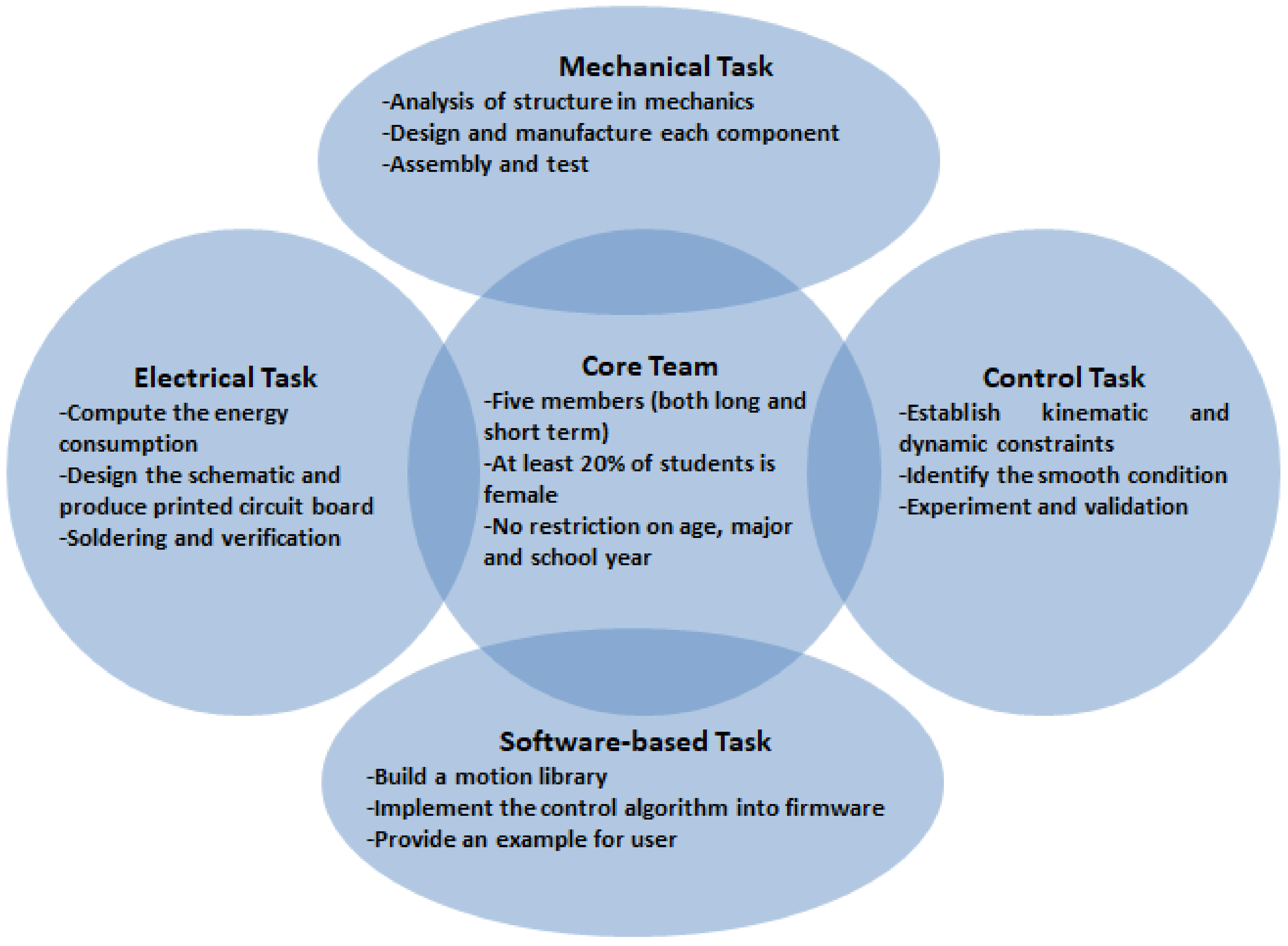
To stimulate collaborative friendship and diversity, team formation should feature two characteristics: multidisciplinary and integrated members. From across engineering and around the university, undergraduate students are welcomed to engage in innovation. The core members, who continuously participate over several semesters, also make continuous progress. Conversely, fresh members who take part in the short-term bring novel ideas to the project. By following this method, continuity in team membership from semester to semester can be achieved. The team’s effectiveness persists as long as required to accomplish the job.
The aim of filtering student members is to correctly form project groups. In [65], group-formation was analyzed over the course of information system design. Without group building activities to enlarge united relationships, cross-evaluation could cause internal competition or collision. Likewise, to rate a group’s performance, using only a grade is sometimes unsuitable. Our strategy examines not only individual learning profiles but also student efforts. In detail, to balance the teams, member candidates are asked to answer a questionnaire (Table 2) to estimate their profiles and are assigned to groups based on their suitable skills to achieve maximum performance. It is better to combine various points of weakness and strength within a team to complement and promote each member’s commitment and coordination so that the group’s goal can be achieved. The targets of this survey are to discover learner’s abilities and favourite jobs. Furthermore, members are chosen based on gender equality and mixed majors, as shown in Figure 2. As a constraint, at least 20% of team members are female, and two students with the same major are unable to enter one team. Students could become principal members if they join over the long term. The main members then act as mentees for newcomers. Group selection also does not distinguish between ages, school years, or fields. Additionally, team followers should understand their goals clearly and have sufficient abilities to handle their tasks completely.
Indeed, the continuous improvement of group performance is a crucial factor to achieve superior results. Applicants are encouraged to frequently assess each other via tools such as oral discussion, inspection sheets, or presentations. The rubric used to judge attitude, team spirit, level of contribution, and soft skills is presented in Appendix B. It is expected that, in this self-evaluation process, the outcomes of the project will be enriched considerably.
The literature points to the importance of face-to-face mentoring activities and the qualities needed to facilitate professional development, such as dissociating and being approachable to others. Professional development in education is open-ended and built on independent judgements based on critical reflections [66], while the mediating skills and emotional intelligence help analyze and address technical challenges [67]. However, the ways to develop these skills were less strongly emphasized. For these reasons, Table 3 explains contrasting points between our approach and others. Without mentoring events, traditional education produces crucial weaknesses in modern society. In previous studies, most topics were related to activities in class [68] or mentoring education [69,70]. These studies used teachers as mentors and evaluated learning performance via theoretical lessons and student attitudes. Learners acquired problem-based thinking from their knowledge in the subjects of the fundamental sciences. At the university level, mentor teachers judged the output results to maintain learning interest. Our mentoring pursuits seek to serve the community through practical knowledge, thereby providing both technological skills and business mindsets, as well as assisting undergraduate students in acquainting themselves with the service learning concept.

4.5. Analysis of the Open Robotics Platform

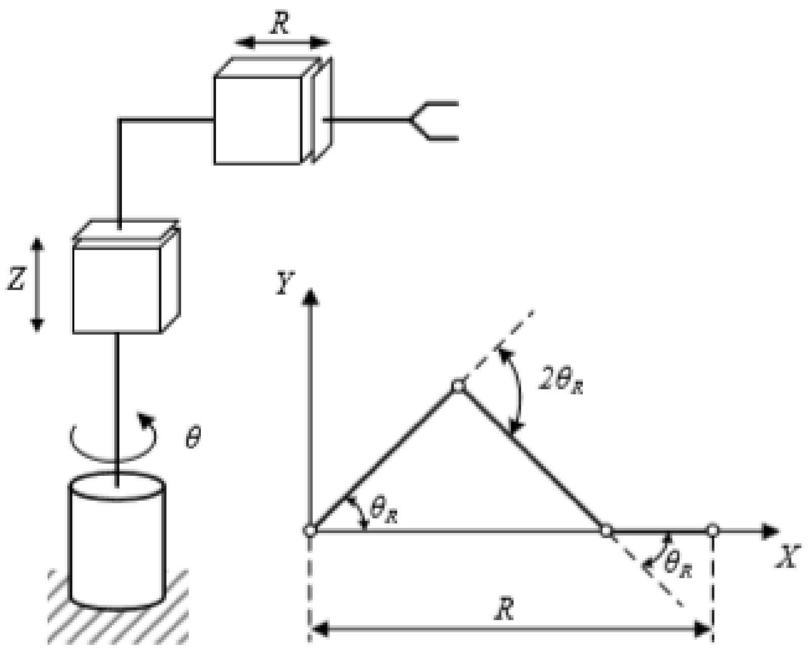
The role of robots in practical scenarios is recognized by society and industry [71,72]. In the applications of semiconductors, only a robot is allowed to handle the wafer in the working environment. A wafer robot was chosen as the target framework to highlight the social impact of Mechatronics incorporation with other majors. The purpose of this design is to provide flexible movement, limited control axes, and smooth motion. The main structure of the handling robot is illustrated in Figure 3. It includes the kinematics constraints of the whole system to ensure that the third axis always moves in a linear direction.
Where θ denotes rotation angle around Z-axis, Z, linear movement along the Z-axis (up, down), R, linear movement along the X-axis (left, right).
Generally, the robot has three DOFs (R, θ, Z) and includes four main components: a radial linear stretching component, a lift and rotation component, an end-effector, and a base. In each joint, the AC (Alternating Current) servo motor is connected to a driving mechanism via a belt transmission that has the benefits of smooth movement at a high velocity, a fixed gear ratio, and a low cost. Particularly, the ball-screw actuator produces linear motion in the Z alignment, as well as driving resources in the R joint. A robot can complete not only a single motion but also optional multi motions at the same time. The strongest benefit of this manipulator is its ability to rotate all constrained joints so that the third joint is always moved in a linear direction. Table 4 shows the technical specifications of this design (the working site, maximum velocity, and errors).
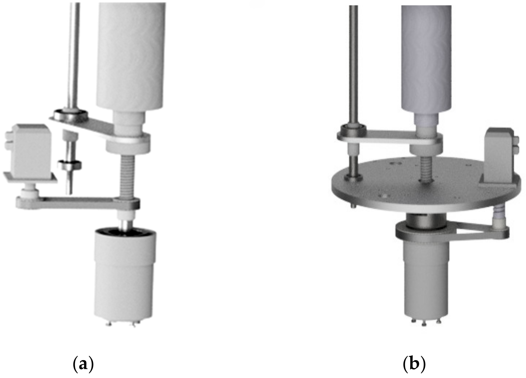
The detailed design is analyzed as follows. For the lift and rotation component (Figure 4a), movement is driven by the lift nut of the ball screw forced by the ball screw. The power, which is transmitted by the timing belt components, is supported by the servo-motor. It is necessary to implement a rolling guide spline bearing. This design is optimal for a mechanism that performs linear motion while transmitting a torque. For θ-movement, as shown in Figure 4b, this displacement is obtained by a planetary cyclic gear train that consists of a timing belt component. The rotation platform and the components fixed on it are forced by the servo-motor.
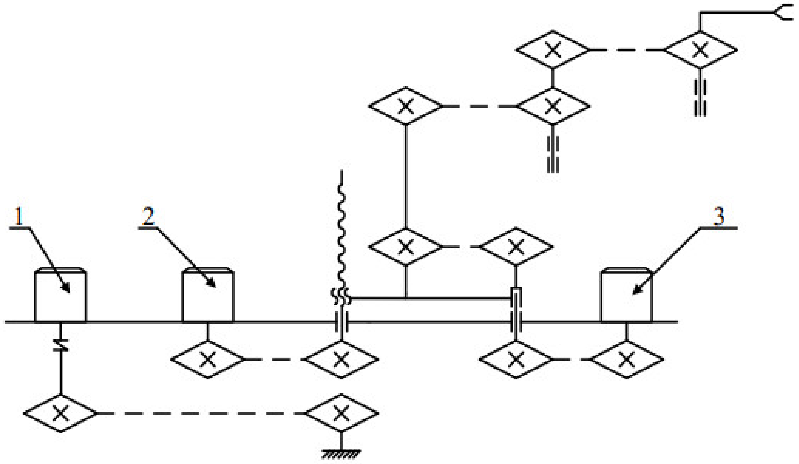
In the third joint, R-movement (Figure 5) is promoted by two correlative timing belt structures located in the first and second part of the elbow, and the rotation ratios are different, such as 2:1 and 1:2, respectively.

5. Learning Examples

This section describes the lessons of the open platform from various perspectives. Specifically, students should employ their knowledge to collaborate with others from the mechanics, electronics, software, control automation, and mechatronics fields. Previously, the working process had many issues since engineers managed only individual jobs. Instead of separating the sequences, the engineering students maintained a parallel structure of work management. The advantages of this organization are the ability to share design information in a group and collect a novel idea under different viewpoints.

5.1. Mechanical Lessons

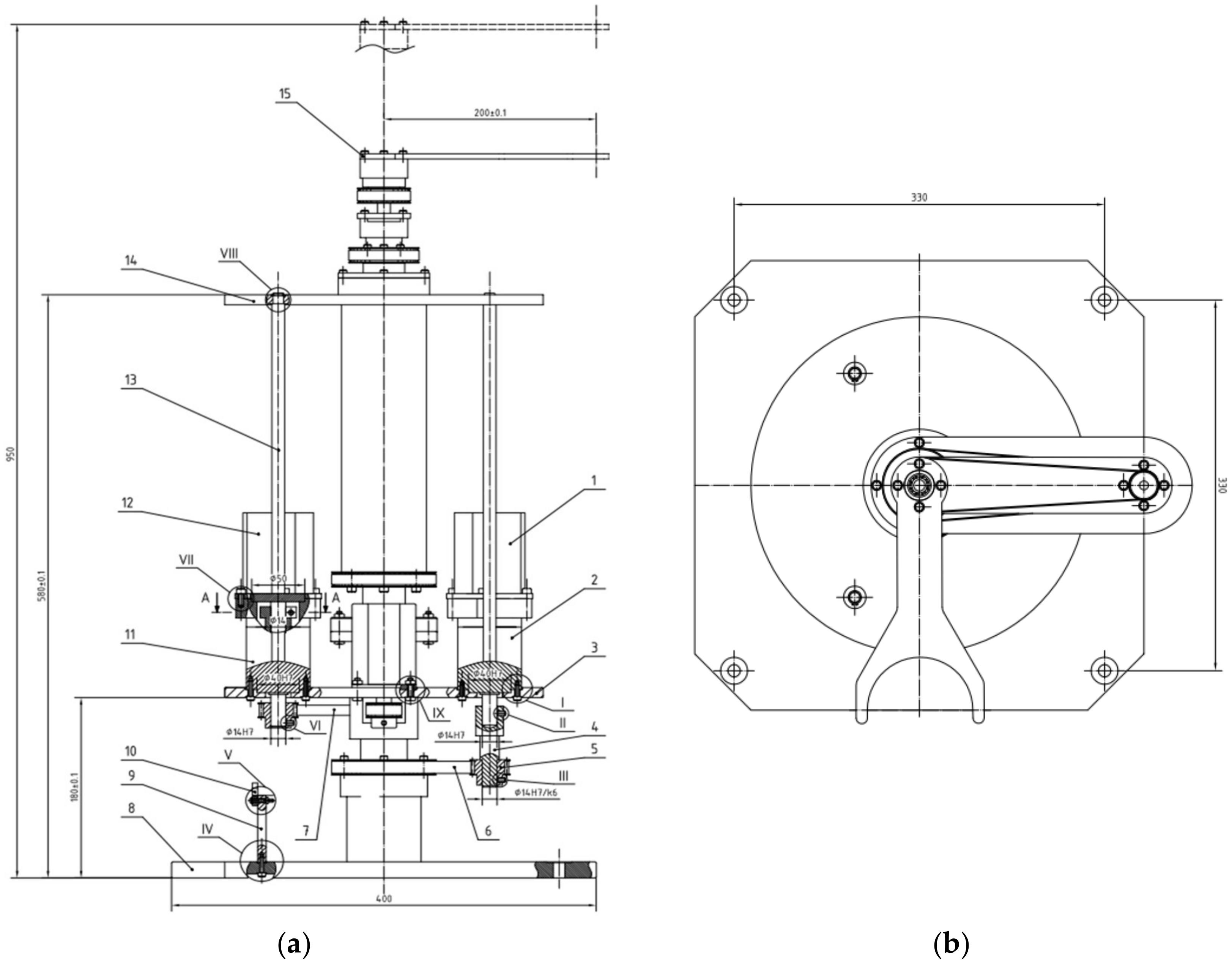
For those who study mechanical engineering, it is obligatory to design theoretical drawings based on the principles of mechanics, as shown in Figure 6. Based on the requirements of the production line, eight working hours per day, three hundred days per year, and ten years of machinery life are the input data for the machine-driven design process. The whole working time is approximately 19,200 h. To satisfy the durability characteristics, the selected material is steel C45, which permits a max tensor of 70 Mpa. Axial computation is one of the most important skills at this stage.
Using their specialized knowledge, the mechanics students must determine the physical dimension of the driving axis. To do that, each joint is analyzed separately.
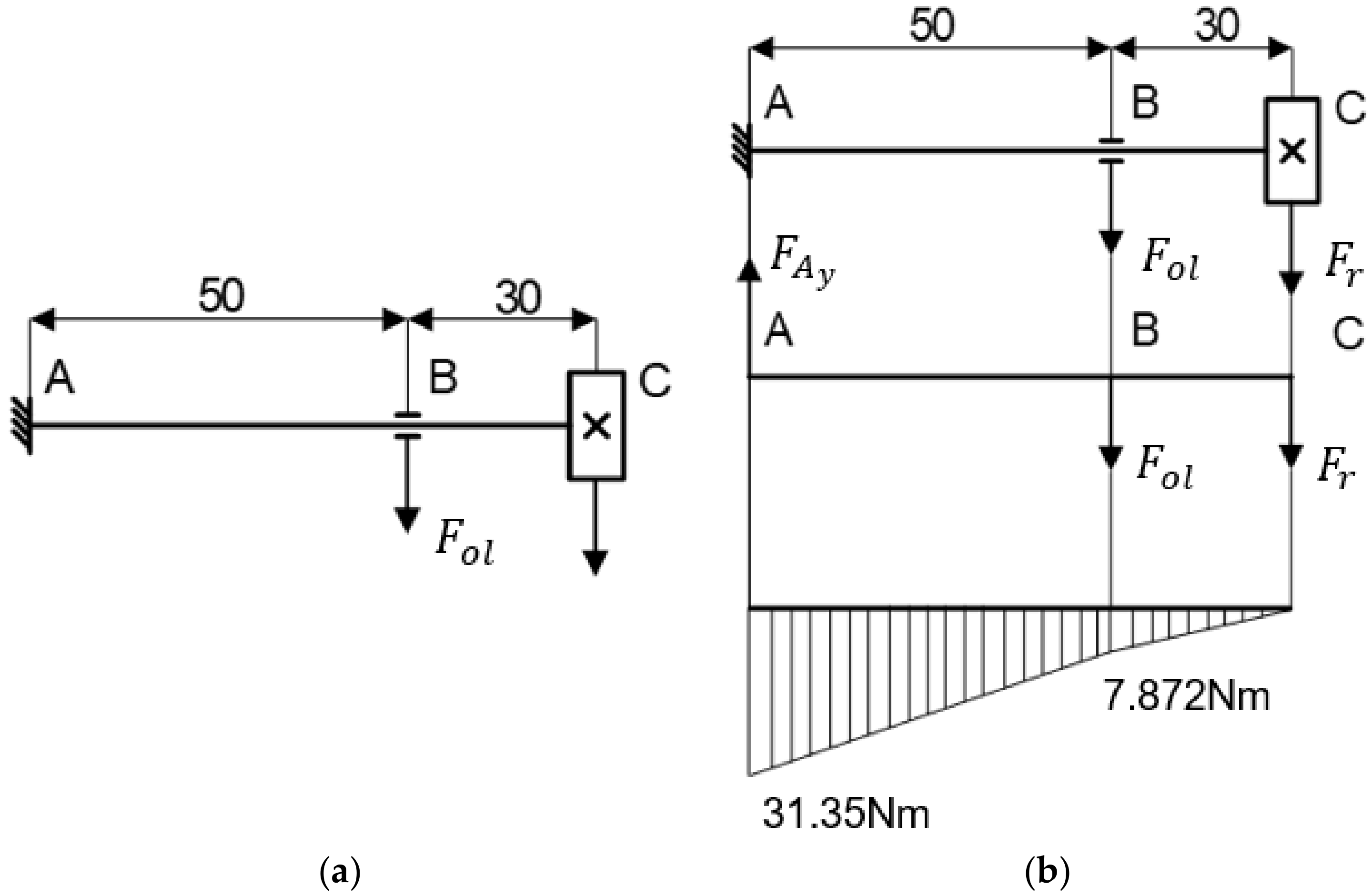
Briefly, we consider F r and F o l as the forces acting on the gear and bearing, estimated to be around 264.8 N and 203.4 N, respectively. Using the second law of Newton, as in Figure 7a, we obtain the following equation:
F r + F o l R A y = 0
R A y = F r + F o l = 264.8 + 203.4 = 468.2   N
From Figure 7b, the bending moment at the weak position is MA = 31.35 Nm. As a result, the axial diameter must be the following:
d M A 0.1 σ 3 = 31350 0.1 × 70 3 = 16.48   m m
Similarly, the model of forces in Figure 8a is demonstrated as:
F r + F o l = 0
R A y = F o l = 264.8  
The bending moment at the weak position in Figure 8b is MA = 13.24 Nm.
d M A 0.1 σ 3 = 13240 0.1 × 70 3 = 12.36   mm
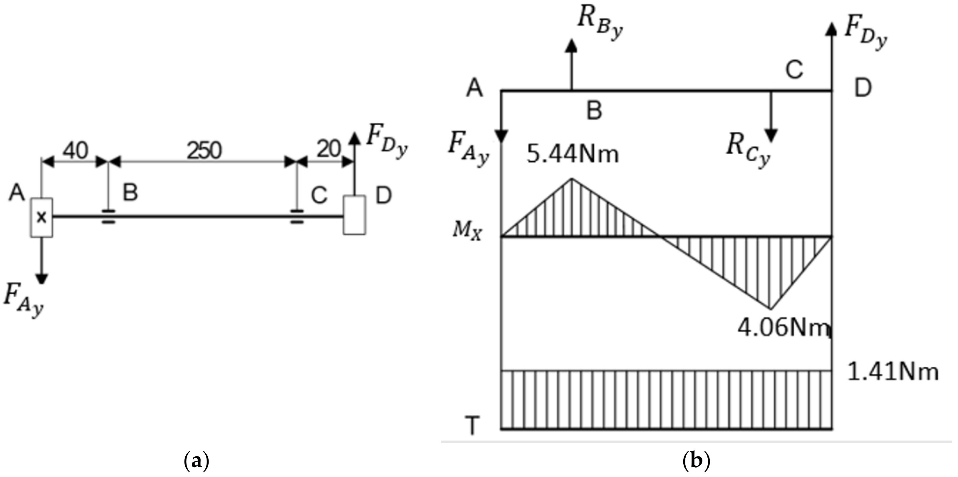
Lastly, based on the model of forces in Figure 9a at node B with the estimated values of FAy = 136 N and FDy = 203.4 N, the equation of the moment in Figure 9b is
F D y 270 + F A y 40 R C y 250 = 0
R C y = 241.4   N
and equation of the forces is
F A y + R C y = R B y + F D y
R B y = 174   N
M B = ( M x B ) 2 + 0.75 T B 2 = 5.44 2 + 0.75 × 1.41 2 = 5.58   N m
d M B 0.1 σ 3 = 5580 0.1 × 70 3 = 9.27   m m
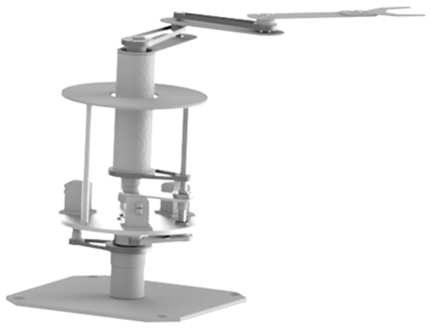
From these computations, the key factors in mechanical design are identified. In sequence, mechanical engineers can use computer-aided tools with the above values. The simulations in the virtual environment in Figure 10 help students visualize their model, predict unexpected errors, and adjust what they need. Some analyses of mechanical design should be carefully considered in the 3D version (Figure 11). Intuitively, learners could establish the working space of a robot in which the robot can outstretch to the ranging area.

5.2. Electrical Lessons

For the development of electrics, undergraduate students can use an applicable tool design like Altium or Orcad. They can refer once to open-source schematics online if they lack experience in the electrical field. Figure 12 presents the general connections in the motion controller. Students can control the robot from their personal computers and manage the entire execution remotely. The most remarkable factor in this section is that three different power supplies co-exist in the same system: 3.3 V for the micro-processor, 5 V for the other peripherals, and 24 V for the servo interface.
In an effort to develop the whole system for the domestic market, the control structure is investigated as in Figure 13a. The central processor unit is an ARM Cortex M3 with a high speed up to 120 MHz, 128 KB SRAM (static random access memory), 1 MB Flash memory, and powerful computation abilities. The data communicate with the host PC (Personal Computer) via the USB (Universal Serial Bus) protocol. The control signal is converted to a pulse train for delivery to the servo driver. The model of the servo motor is SGMJV-02ADA21 Sigma V 200W, with a max speed of 3000 rpm. The GPIO (General Purpose Input Output) module interfaces with the limit sensors, home sensors, and buttons or switches. The mainboard explained in Figure 13b involves four layers: the top layer, signal layer, power layer, and bottom layer.
All electronic components are positioned in the basement. The operating voltage of the peripherals ranges from 3.3 V to 5 V, while the 5 V voltage supply comes from a power source. However, the main microprocessor works using a 0 V to 3.3 V voltage that does not match that of other interface chips. To overcome this problem, the shifting voltage level is realized by using a pull-down resistor array. This connection serves to enhance the exchanging value measurement. Generally, PCB design is compulsory to respect system stability and industrial standards. Internally, the electronic components are fixed to the upper portion or the lower portion. Some positions are located such that the control signal should not be placed near the power signal, while the copper wiring of the crystal oscillator is not located under any IC. The high-speed differential line drivers and receivers serve an intermediate role to transmit between the servo side and controller side. While moving, an unexpected noise may occur, and its impact may lead to broken connections. Extra filters could reject external disturbances in more detail.

5.3. Software Programming Skills

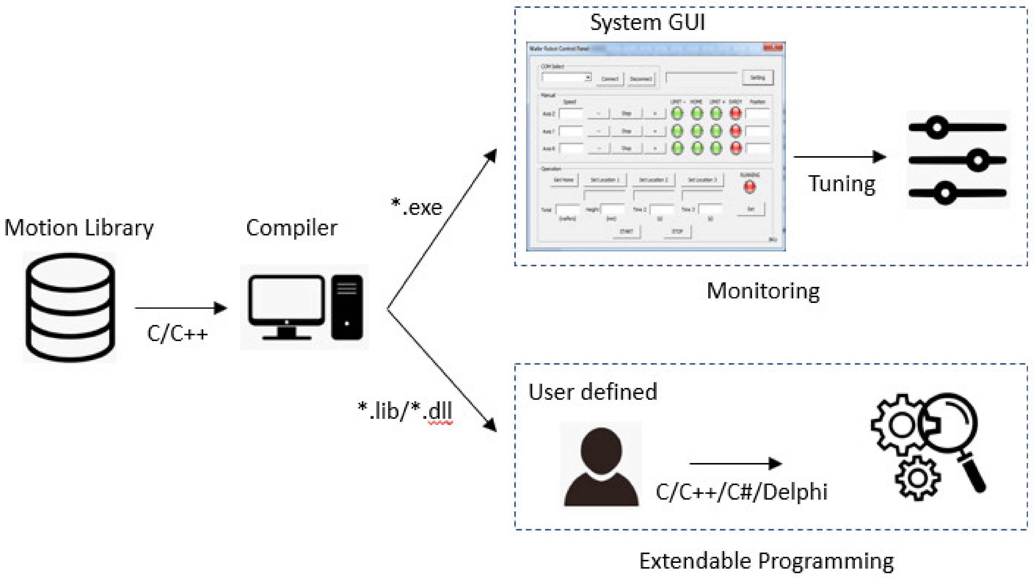
A programming tool that could be used for a wide variety of robotic platforms is C/C++ with the Microsoft Foundation Class. The general framework of software development is mentioned in Figure 14.
The basic functionality for hardware open access provided by a motion control dictionary is extended in two ways. The first one involves a dynamic link library (*.dll file) associated with a certain motion API (application programming interface). The benefits of this type are its ability to reduce file capacity and rapid processing. The second way is to use a static library (*.library) to offer additional access. The advantage of a static motion dictionary is its ability to supply the rights for anyone to enter into the physical hardware. This well-supported access allows nonprofessional undergraduates to thoroughly comprehend the relevant principles.
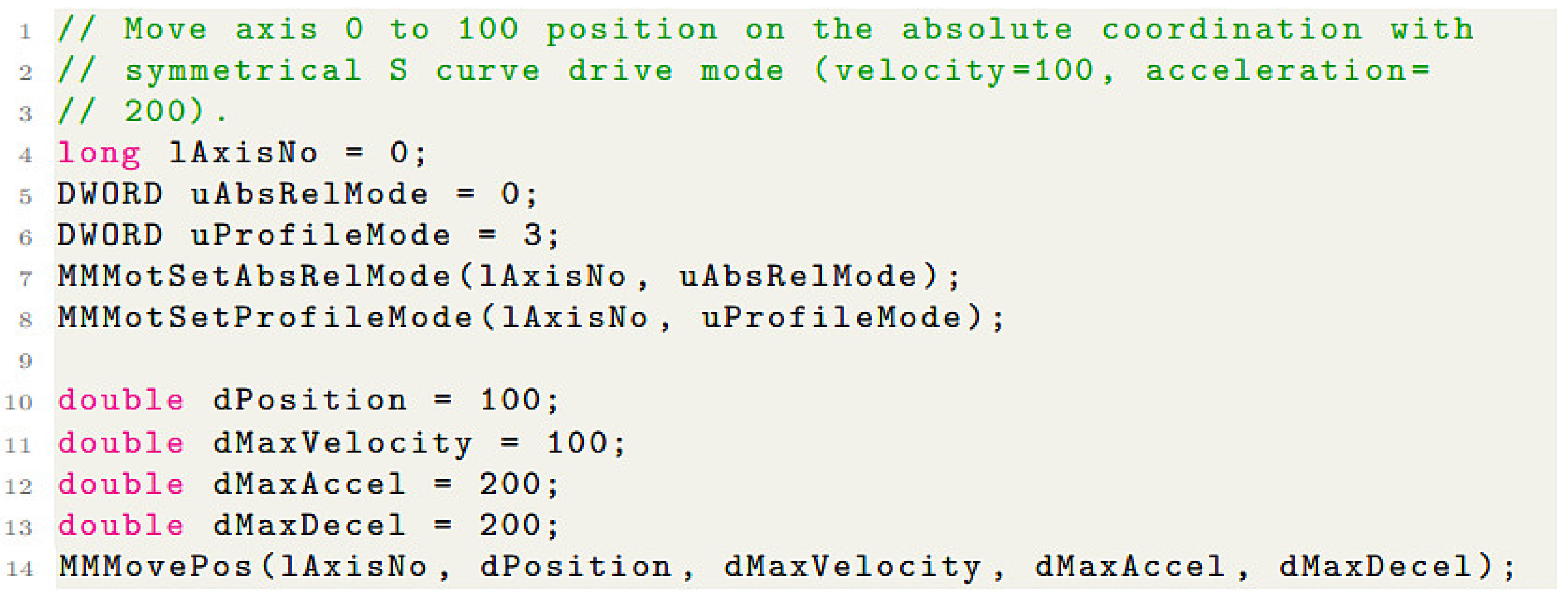
The structure of API functions is described in Table 5, where ‘MM’ stands for multidisciplinary mechatronics. The classes of functions are initialization and exit, motion setting, and motion drive. To manage and access the devices of the robot, the generic input parameters include various options for each type of device, as well as the motion modes to associate with the dictionary.
The example code of the first test, the position drive, is shown in Figure 15. This test consists of the creation of definition for variable types and coefficient instances. Some selections for the operating mode need to be declared first; otherwise, the motion program works with the default values. As can be seen in the test code, the specific motion is the absolute mode, and the asymmetrical S-curve profile produces smooth motion and stable movement. The results of the execution of this test can be validated using our open robotics platform. Simple programming, easy teachability, and user-defined interface are the primary merits of this approach.
Through a virtual serial communication on a personal computer, the data flow between the robot and host is established. In each axis, the blinking LEDs consist of plus/minus limit sensors with sufficient range for moving displacement and a home sensor that marks the origin and the servo’s readiness. There are two operating modes: the jogging and positioning modes. In the jogging mode, the user is required to hold the directional buttons to drive continuously. If the servo motor is programmed in advance to include the value of the position, velocity, acceleration, and jerk, the driving axis can track the reference trajectory in the positioning mode. The value of the target position is categorized into absolute and relative calculations. Based on these values, the motion generator outputs several pulses following the motion profile. As a result, the movement of all axes is smooth, vibration-less, and features a pre-determined trajectory.

5.4. Automation Lessons

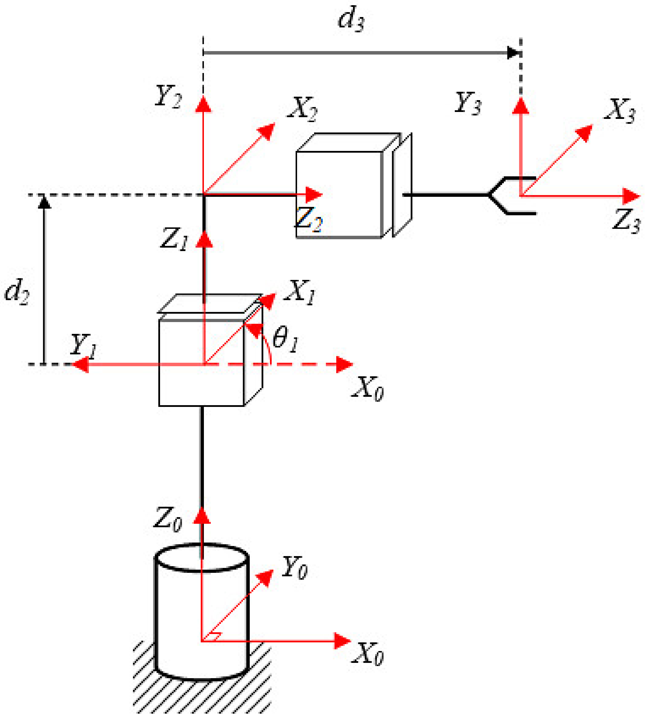
Before starting the actual execution of a prototype, the students need to be equipped with knowledge of automation. The instructors provide step-by-step guidelines on how to control the robot’s movements, automated functions, and global mapping. In this step, the undergraduate students should become familiar with some terms in automation and develop strong computational skills. Teachers also suggest several bottleneck points to clarify the purpose of the project. To analyze the kinematics formulation, coordinate frames are attached to the joints between two links, as shown in Figure 16.
Corresponding to the coordinates, the parameters in the DH (Denavit-Hartenberg) transformation matrix are listed in Table 6, where αi: angle about the common normal; di: length of the common normal; ai: offset along the axis to the common normal; θi: angle about the axis.
From the above information, the transformation matrix from one link to another is expressed as:
T 0 1 = cos θ 1 sin θ 1 0 0 sin θ 1 cos θ 1 0 0 0 0 1 1 0 0 0 1
T 1 2 = 1 0 0 0 0 0 1 0 0 1 0 d 2 0 0 0 1
T 2 3 = 1 0 0 0 0 1 0 0 0 0 1 d 3 0 0 0 1
Thus, the transformation information from link 0 to link 3 can be formulated as:
T 0 3 = cos θ 1 0 sin θ 1 d 3 sin θ 1 sin θ 1 0 cos θ 1 d 3 cos θ 1 0 1 1 1 + d 2 0 0 0 1
With the location of the end-effector in workspace x   y   z , the relationship between links is recognized. Equation (17) determines the forward kinematics of the handling robot:
x = d 3 sin θ 1 y = d 3 cos θ 1 z = 1 + d 2
By using kinematics equations to identify the joint parameters, inverse kinematics provides the desired position for each of the robot’s links:
θ 1 = arctan x y d 3 = x sin θ 1 d 2 = z 1
The dynamics model is analyzed in Figure 17. The robot arms are classified as bars (OA, AB, BC), and the bar-centers (A0, B0, C0) are placed at geometric centering points. OA, which is the first link, only comprises rotation, and its angular velocity is θ ˙ 1 . BC, which is the end-effector, only includes translation, and the velocity V B is defined as below.
V B = 2 l ω sin θ 1
Suppose that l 1 = l 2 = l 3 = l , ω A O = ω , ω B A = ω and ω C B = 0 . AB, which is the second link, contains not only rotation but also translation, and its velocity can be calculated as follows.
The bar-centric coordinate B0 of AB is obtained by calculating
x B o = 3 l cos θ 1 2 y B o = l sin θ 1 2
After applying the derivative of (20), we have
x ˙ B o = 3 l θ ˙ 1 sin θ 1 2 y ˙ B o = l θ ˙ 1 cos θ 1 2
Then,
V B o 2 = l 2 θ ˙ 1 2 0.25 + 2 sin 2 θ 1
Based on the Lagrange equation, where L is the Lagrange function, K is kinetic energy, and P is potential energy, we obtain the following equation:
L = K − P
Consider that Z = 0 and P = 0. Equation (23) can then be rewritten as
L = K 1 + K 2 + K 3 = I 1 θ ˙ 1 2 2 + I 2 θ ˙ 1 + θ ˙ 2 2 2 + m 2 V B o 2 2 + m 3 V C o 2 2 = l 2 θ ˙ 1 2 m 1 + m 2 6 + m 2 + 2 m 3 sin 2 θ 1
where θ ˙ i is angular velocity, I i is the moment of inertia, m i is mass, and i = 1, 2, 3.
By applying the Lagrange equation for dynamics, we have
T i = L θ ˙ i t L θ ˙ i
where Ti is the sum of external torques. By performing a derivation, we obtain the external torque of the first link:
T i = X θ 1 θ ¨ 1 θ ˙ 1 + Y θ 1 θ ˙ 1 2
where
X θ 1 = 2 l 2 m 1 + m 2 6 + m 2 + 2 m 3 sin 2 θ 1
Here, the velocity of the end-effector v e n d - e f f e c t o r m a x and the angular velocity’s θ ˙ limit can be calculated:
Y θ 1 = 2 l 2 m 2 + 2 m 3 sin 2 θ 1

5.5. Laboratory in Mechatronics

The speed of movement in the Z-direction and θ-direction is proportional to the speed of the motor. As a result, an S-curve profile is chosen to control the position of the motor directly. The velocity of the R-joint is also investigated in this paper. The maximum angular velocity curve in the θ θ ˙ phase plane of the first arm, based on the rated rotational speed of the servo-motor v s e r v o - m o t o r m a x , the rotation ratios η , and the limit
θ ˙ v s e r v o - m o t o r m a x η θ ˙ v e n d - e f f e c t o r m a x 2 l sin θ θ ˙ 69.77 θ ˙ 0.5 sin θ
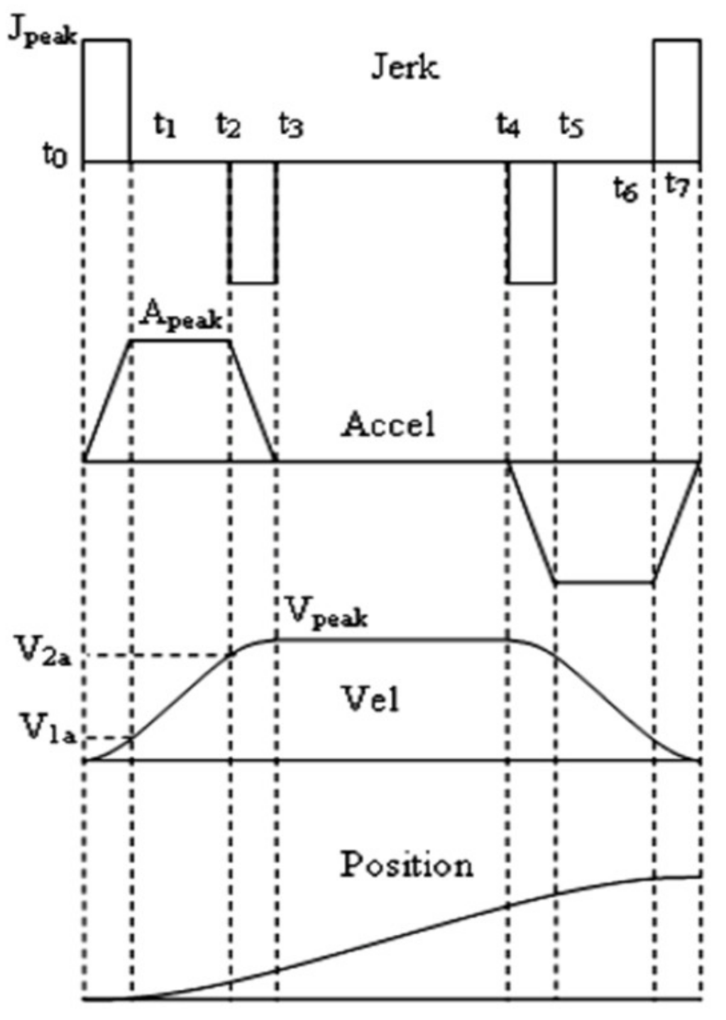
is shown in Figure 18. This equation determines the desired angular velocity for the first joint so that the end-effector is can frequently achieve max velocity as it tracks the trajectory. Hence, to guarantee stability and smoothness, it is necessary to control the robot from 0.5 rad to 2.5 rad, while the S-curve profile in Figure 19 is applied for positional control of the industrial motor.
The pulse train of the controller is based on the symmetric S-curve profile. The motion profile is built as a polynomial function. The model of the 3rd order polynomial model is defined by the following expression. For polynomial models whose orders are higher than two, the jerks exhibit finite values. Thus, their velocity profiles are smooth during motion.
j = J p e a k t 0 t t 1 J p e a k t 2 t t 3 J p e a k t 4 t t 5 J p e a k t 6 t t 7
The parameters of motion planning are as follows:
  • t j only depends on j and x ¯ :
    t j = x j max 3 ; a max = j max t j
  • Compare a m a x and a m a x i m a l ;
  • If a m a x i m a l < a m a x , then given t j , we obtain t a = 0 ; compute v m a x i m a l = j m a x t j 2 ; compare v m a x and v m a x i m a l ; If v m a x i m a l < v m a x , then t v = 0 ; If v m a x i m a l > v m a x , then calculate t j again, and
    t v = x 2 j max t j 3 v max
  • If a m a x i m a l > a m a x then
    t j = a max j max
t a is the solution of the second order equation. Compute v m a x i m a l = j m a x t j 2 + j m a x t j t a ; Compare v m a x and v m a x i m a l ; If v m a x i m a l < v m a x , then t v = 0 ; If v m a x i m a l > v m a x , then calculate t a again, and
t v = x 2 j max t j 3 + 3 2 j max t j 2 t a + 3 2 j max t j t a 2 v max

5.6. Achievements from Multidisciplinary Collaborations

The robot prototype permits students to learn and use information from various academic disciplines, such as manufacturing, electronics, advanced programming, and robotics. This class was first held during the sixth semester and met for four hours per week over a 15-week semester. In a short period of time, the trainees had to recognize and analyze a problem, study a large amount of documentation material, develop and test many solutions, and recommend the best solution. This routine was repeated continuously so that the students could improve their sensitive thinking in techniques and collect more experiences.
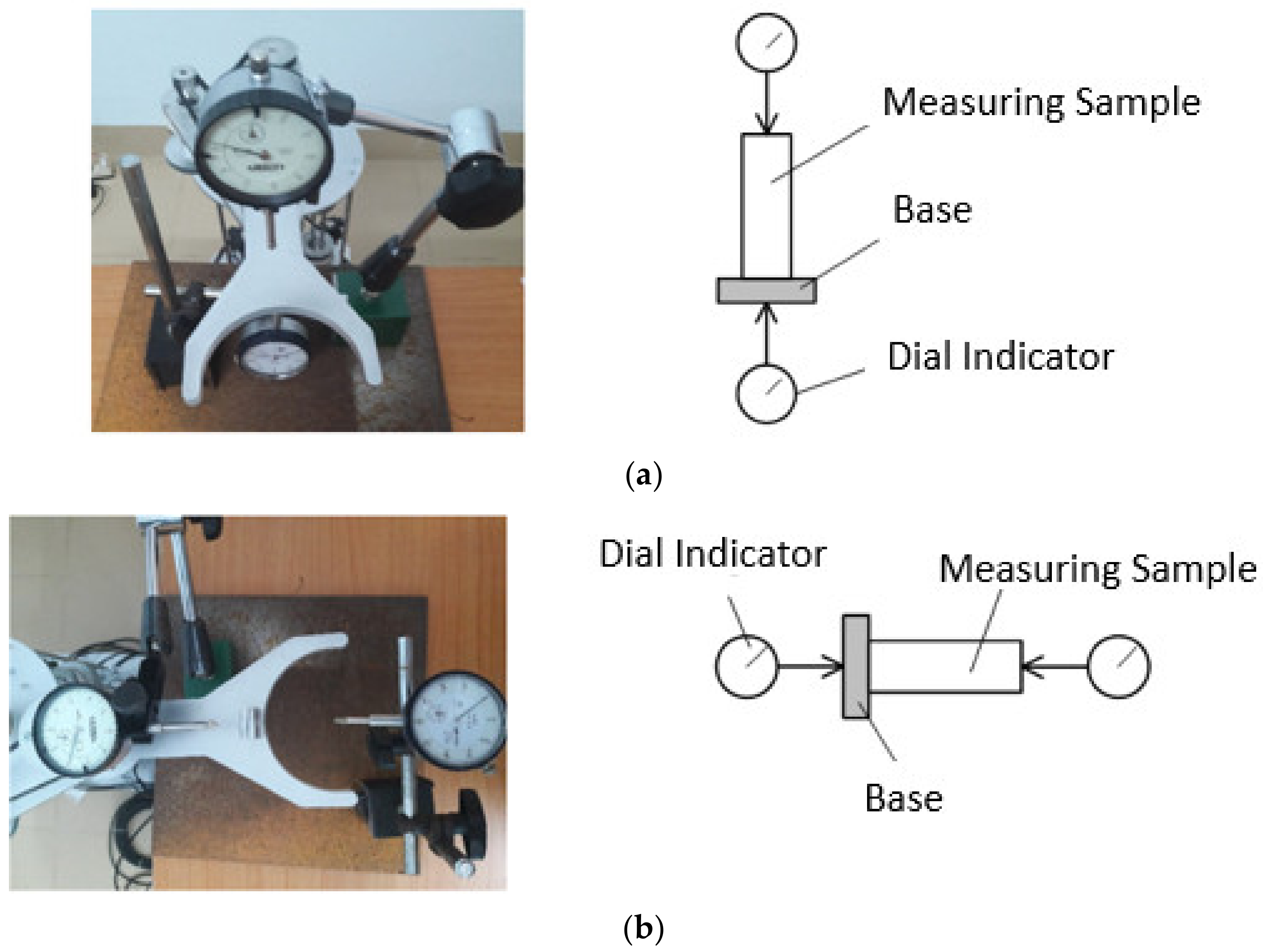
Once undergraduate students obtain jobs in the mechanical sector, it is documented that errors in assembly play a vital role. In this study, students utilized our accessories from the mechanics workshop to calibrate each component. Based on directional movement, the measurements of the Z-axis, R-axis, and θ-rotation are categorized into sub-work. The calibrating process was first handled in the Z-axis. Placing the tools and bases as in Figure 20a, two dial indicators are needed to display any unbalancing event: one indicator on the bottom of the base and the other on the top. The measuring sample ensures that physical distance is correctly estimated. For instance, the sampling displacement, determined for the measuring sample in advance, was 50 mm. Then, the students supplied 5000 pulses to the AC servo motor and calibrated the motor. This action was repeated ten times. In the R-axis, all equipment was set up as in Figure 20b. The base remained on a horizontal plate, and the end-effector was manipulated to position R = 450 mm based on 6000 pulses. Using two dial indicators for both sides of the base, the servo motor was provided 887 pulses to drive a distance of 50 mm and calibrated. This action was repeated ten times. For θ-rotation, an incremental encoder was attached on the rotational axis. Then, the students output 4500 pulses corresponding to 45° and read the feedback signal. This action was also repeated ten times. All calibration values are recorded in Table 7.
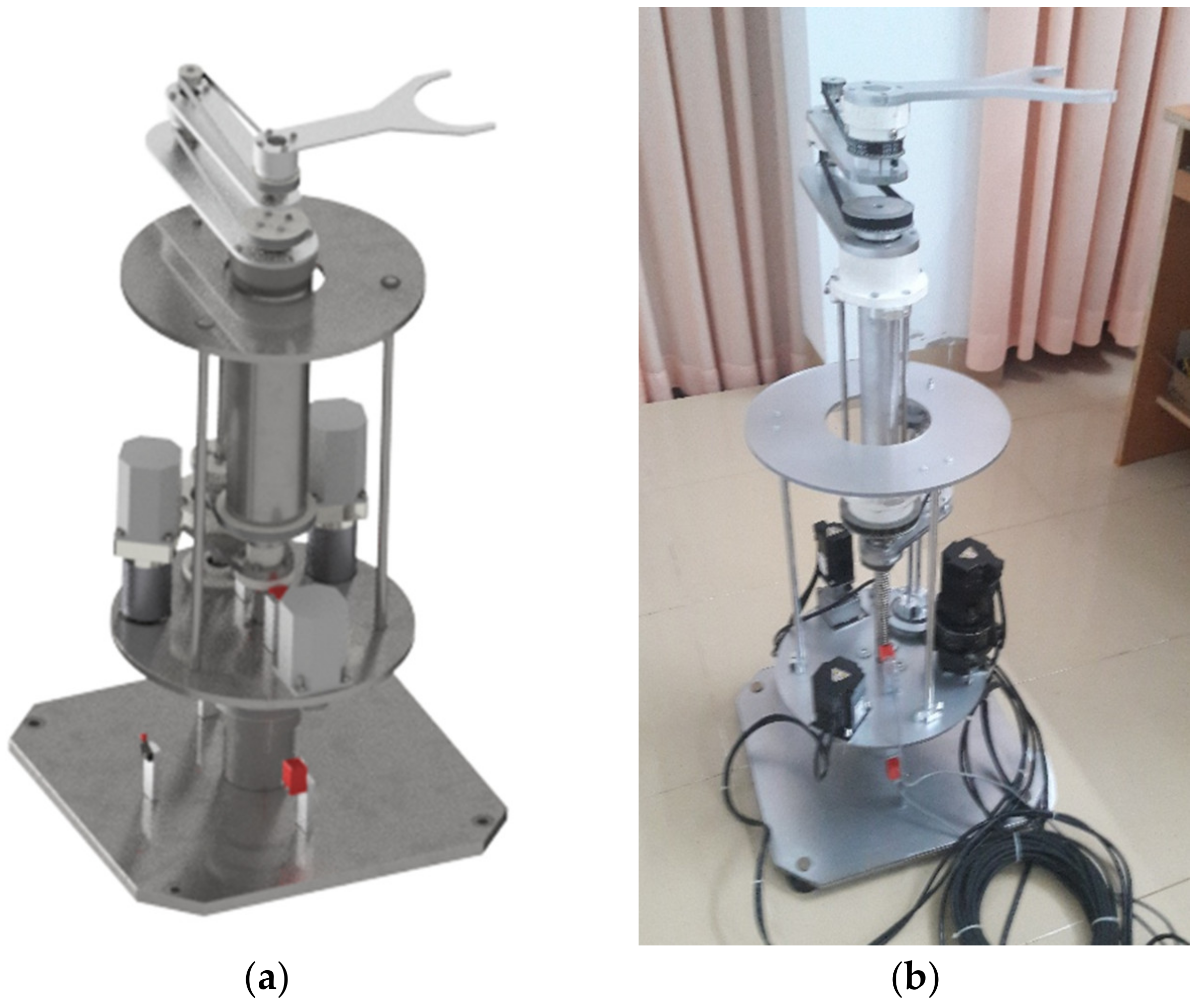
The laboratory results indicate that a change in strategy could cause significant gains in student learning success. The open platform in both the virtual environment and experiment after passing the trials is shown in Figure 21. In the assembly process, pupils become familiar with the definition of mechanical tolerance and validate it. The practical manipulation relies on mechanical standards to ensure stable movement.
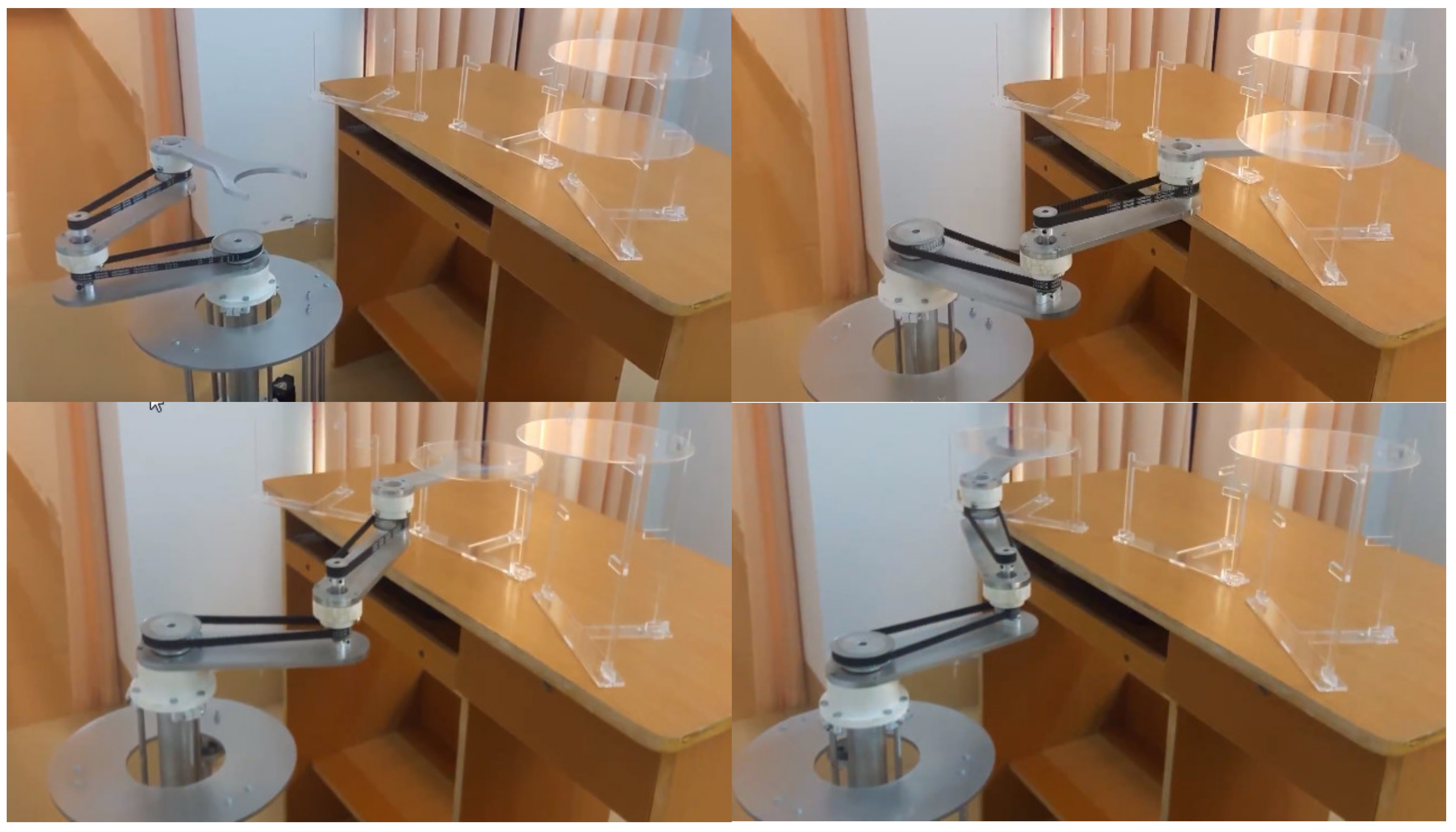
To confirm their success in design, multiple tasks were scheduled for the robot hand, as shown in Figure 22. In the demonstration, the robotic platform is used to transport a wafer disc from one place to another. We assume that all coordinates are known and that the calibration process must be done before the starting command. This means that the system parameters, including velocity, acceleration, positive/negative limitations, etc., are not violated.
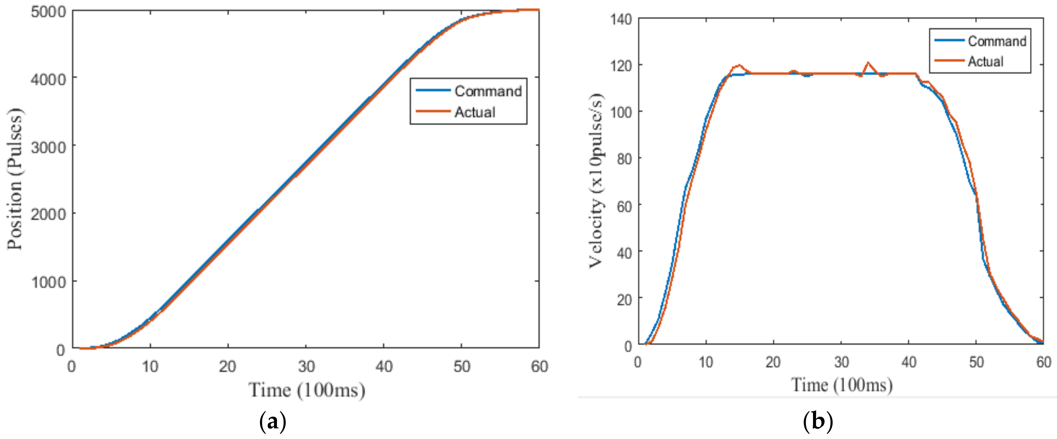
To match the practical scenarios, the experimental results in different cases are demonstrated in Figure 23. From various initial conditions, the polynomial expressions of the profile correspond to the fourth, fifth, sixth, and seventh orders, correspondingly. The proposed algorithm must cover entire situations to fill the operating domain. In any circumstance, the motion of the wafer robot can be ensured to offer smoothness and precision.
A shown in Figure 24, the panel control was visually handled by trainees in class. To efficiently imitate/emulate the working environment of a real factory, the GUI provides a set of typical functions to the students/operators for remotely controlling the robotic system. These functions can be classified as follows.
(1)
Initially, a serial connection requires choosing a port number for the selected COM (Communication Port). On the computer side, the idle frame is set to acknowledge the communication and synchronize data between the host and the controller. After establishing the connection, the default parameters of the motion profile, including the soft limit, velocity, acceleration, jerk, and others, are modified by users via the “Setting” button. Then, the servo system is ready to start.
(2)
Generally, there are two operating modes, manual and automatic, in this robot platform. When controlling the system step-by-step or manually, Jog functions and manual pulse generation are essential to drive the motor. Otherwise, the input parameters for entire movements can be defined primarily. Clicking the “Start” button then activates the automatic operating mode.
(3)
Eventually, students are able to allow multiple axes to move simultaneously in one turn. The constraint parameters are input for all servo motors before triggering motion. Whenever electricity is suddenly cut or the motion re-starts, the homing mode is employed to take all motors back to their starting points. For warning notifications, LED (light-emitting diode) indicators with two colors, red and green, are used to appraise users of the system status.

6. Discussion

The results show that students learned the following:
  • A solid understanding of robotic perceptions, from theoretical principles to practical activities. Despite their diverse specialized fields, the students were able to express their passion in mechatronics.
  • Knowledge of manufacturing, assembly, embedded systems, advanced programming, and control algorithms.
  • The ability to perform laboratory tests and verifications. The inclusion of working at a mechanical workshop, data processing, and acquiring fundamental experience with industrial standards taught students about safe labour, restrictions, and professional skills.
Additionally, the teaching syllabus was modularized to help pupils logically and orderly understand the relevant factors. By exposing learners to production with hands-on practice, this program developed methodical abilities required to address challenging and motivating real-world engineering problems. Sharing knowledge and attaining obligatory leadership skills are two of the most essential abilities in teamwork.
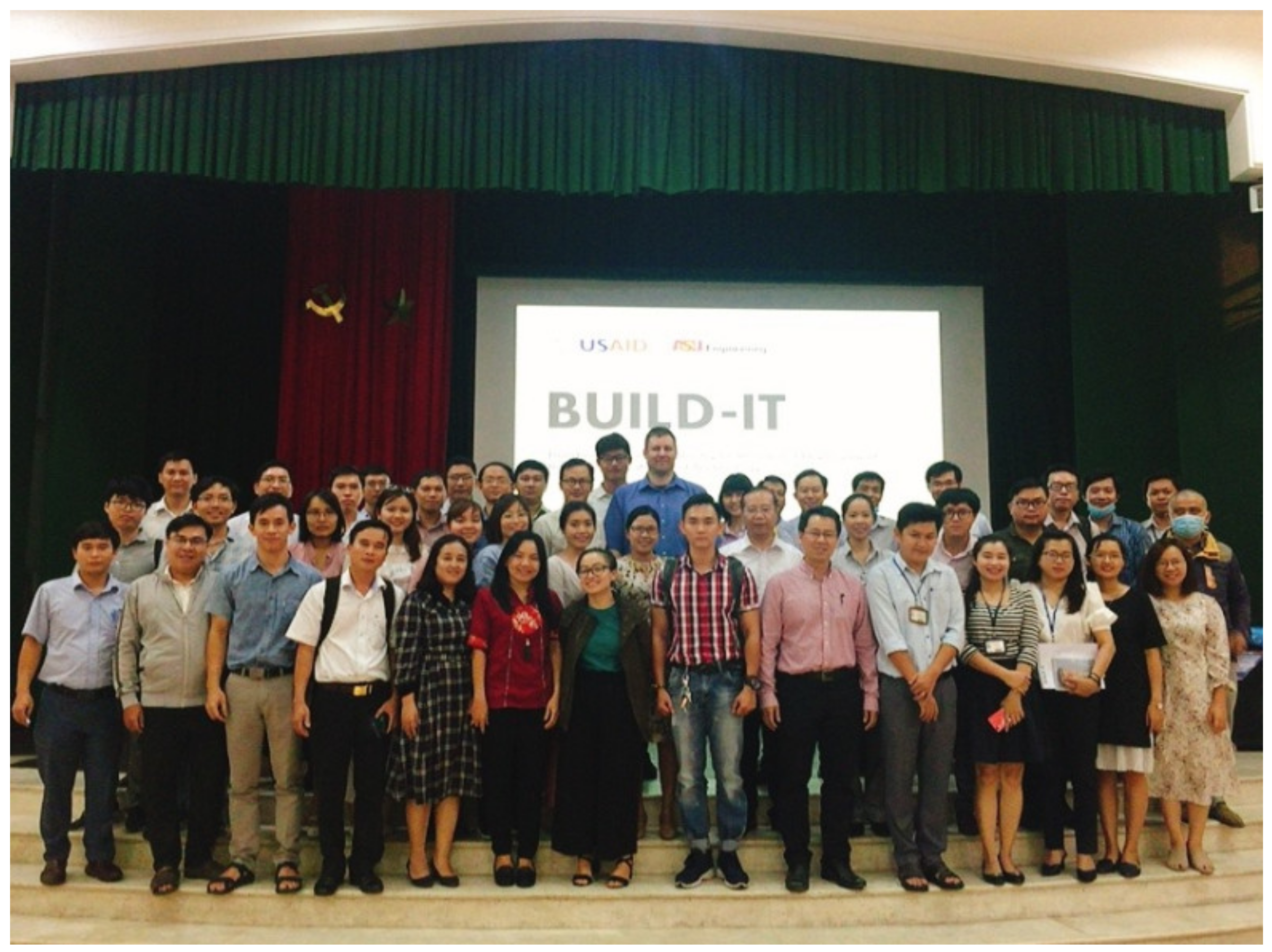
To prepare for the program, faculty members served as local instructors and section advisors because the students were from various fields. To unify the research method and teaching scheme, a training course was employed (Figure 25). The students were required to discuss and agree upon the difficulties they faced. The program faculties were responsible to guide, mentor, assess, and grade the team on their weekly work. Sometimes, a change in the faculty advisors was needed to introduce new human elements. These change in advisors showed that open mechatronics are not dependent on a particular faculty member or vocational mentor.

6.1. Learning from TechShow

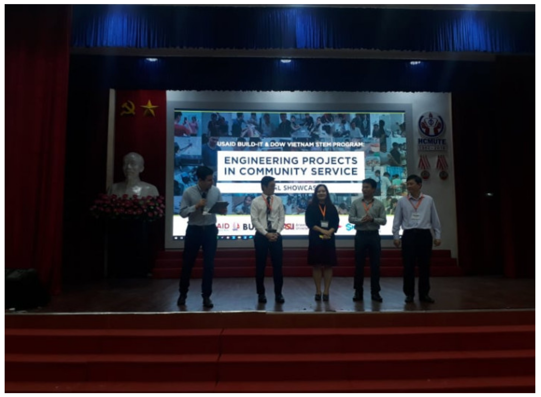
TechShow or ShowCase was the final exhibition in which applicants showcased their achievements. Contributors in this event include academic professors, industry professionals, business professionals, social activists, journalists, and government officials, as shown in Figure 26. Over 100 undergraduate students from numerous universities attended TechShow to authenticate their work. The students were eager to participate since there is no winner or loser. The students simply displayed their work for the benefit of the community and, if possible, to engage in social networking.
The rubric for the final ShowCase is often used to assess whether a student’s project has followed the design process (Table 8).

6.2. Entrepreneur Activities

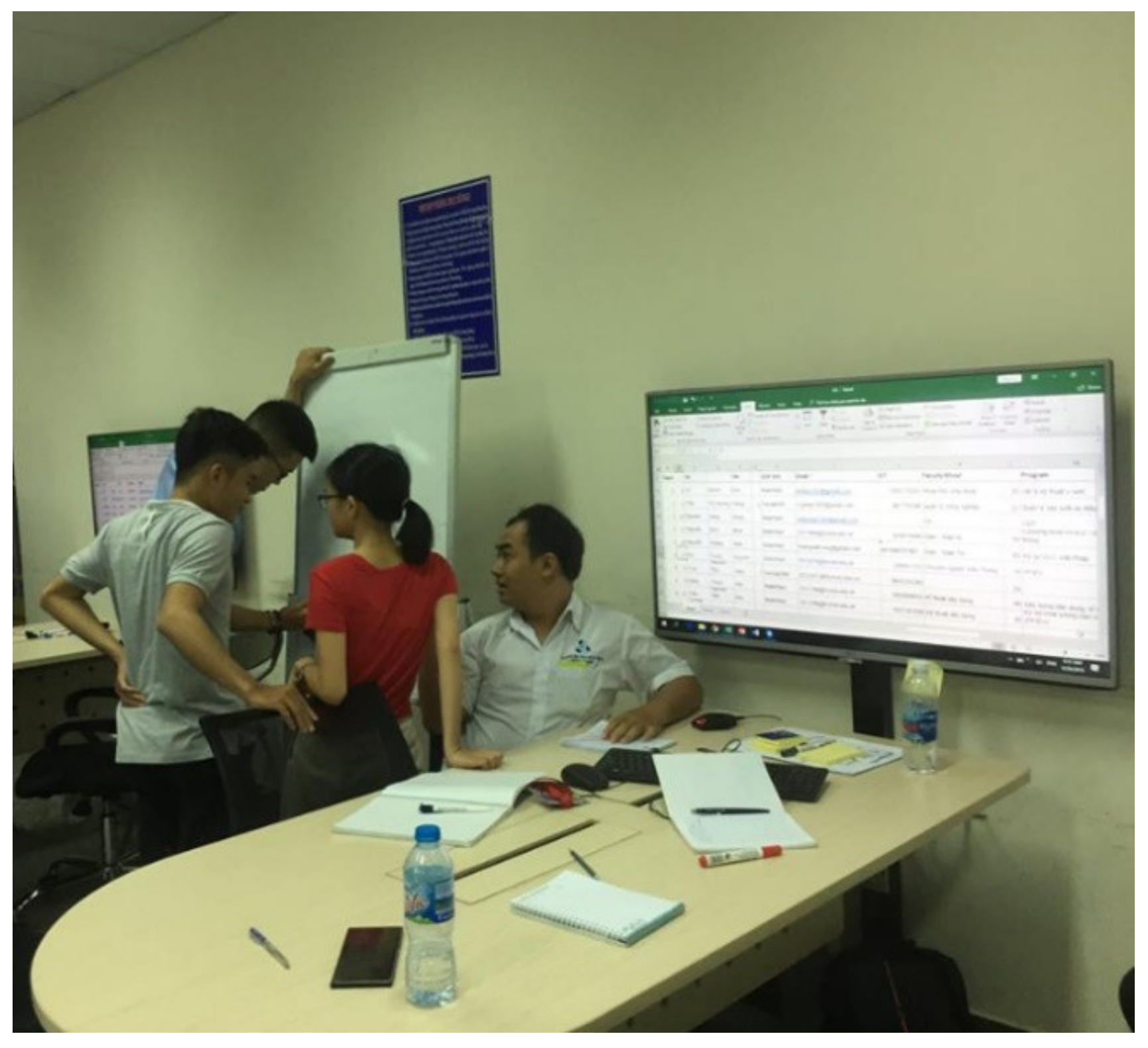
Mentoring, as shown in Figure 27, is an activity where an experienced worker passes on his or her knowledge and expertise to a less experienced worker. In some cases, a mentor might be assigned by management, or a mentoring relationship may occur informally. This process helps fresh engineers acclimate to the job and organization. In our class, mentors had to visit a desk where one team was prepared, discuss scenarios, and generally learn the nuances of the company. In this way, the mentees can become productive members much more quickly and never feel that they have nowhere to turn for help. Likewise, the mentee can gain the sense of achievement that comes from the mentor’s feedback and assessment of his/her progress. The mentor can be satisfied knowing that he/she is helping an individual and can take a measure of pride in their accomplishment.
For more effective work, each team must carry out a lesson plan for mentoring activities. A brief introduction is required. When discussing with mentors, a hand draft should carefully outline the pros and cons, key problems, and experienced solutions. Hence, members need to work at home to discuss and consider advice from mentors. As we held several mentoring days during the class, in the reports, team members also had to clarify their improvements after such consultations.

6.3. Social Impacts

In developing nations, there is a lack of government investment in education, although the needs of society continue to increase considerably. The undergraduate students did not have the motivation to learn more since practical platforms are too expensive and difficult to maintain. To overcome these problems, an innovative training method was investigated with the following considerations: (1) Active learning requires the self-study of learners. Pupils must identify key problems and produce an idea or method for solving a problem; (2) the spirit of teamwork (Figure 28) inspires each member to develop their mindset. With strong attitudes and courage, partners can contribute to their shared success; (3) thanks to the low-cost prototype, the students in various majors, such as mechatronics, energy, and electric or technical management, were shown how automation applies to their fields. There was no regular assessment during this class. Such a class includes an integrated method based on weekly reports, technical notes or experiential records, seminars, oral examinations, or indirect communication.
  • Weekly report: The team is prompted to submit their action program during the week to maintain progress.
  • Technical notes or experiential records: Each undergraduate student experiences problems that they must face. If there are possible solutions, their experiences and understanding of the problem should be recorded (image, video, or flow chart) to share with the community.
  • Seminar: Students represent their progress in front of the class via a poster or an MS power-point slideshow. They explore how soft skills (public speaking, municipal communication, and human attractive techniques) play an important role in connecting people.
  • Oral examination: Trainees answer numerous inquiries based on the system to show their technical knowledge.
  • Intermediate communication: Several meetings with business partners and industrial co-operation supports are used to obtain objective feedback.
Each type of assessment is worth 10% to 20% of the course grade. Rubrics are an excellent way to establish the evaluation criteria and learning outcomes. Rubrics allow students to recognize how to estimate their work both individually and in groups. Habitually, there are two main kinds of rubrics: holistic and analytical. A holistic rubric measures the overall work of the team without dividing it into smaller components, while an analytical report is split into several sub-elements, each of which is judged. In this research, we chose to employ a holistic rubric, as shown in Table 9, to rate the project’s progress and what skills the students gained.
To quantify the overall performance of our approach, the post-activity surveys were accomplished in two ways, immediate measurement and delayed measurement. The immediate survey in Table 10 enabled feedback to be obtained from the attendee. In this way, each student shared his or her feelings and thoughts about the project. Conversely, the delayed survey in Table 11 allows us to develop an objective viewpoint. The report of our activity and the questionnaire for the survey were submitted to our partners.
In both surveys, we received different responses on the level of satisfaction. Students felt very positively about the content and teamwork. To diminish stress and engender a relaxed atmosphere in class, the assessment was performed without an exam. The two most negative types of feedback were related to the difficulty in implementing a practical model (as in a conventional class) and problems sharing jobs among members. To address these concerns, the model of the capstone project or mini project could be better integrated into the subject. The project was reconstructed to assign several related missions that cannot be solved individually so that students necessarily must collaborate to ensure the team success.
Table 12 highlights the advantages and disadvantages of the PBL approach compared to a community-based one. The undergraduate students felt optimistic, as even difficult problems could be addressed and solved. They also became more empathetic; since engineering projects have an immense impact, it is vital that engineers think using a humanistic approach. Additionally, models, prototypes, and failures are opportunities to learn. After the project, the students retained their learning interest in the design process (build, fail, learn, repeat). In practice, learners could enhance their professional skills by embracing the unknown. Very interesting and important problems do not have obvious solutions. Working in teams, the students must learn how to share data, deliver the project goals, and organize activities. They thus become aware that each member must contribute to ensure the group’s success. Moreover, they demonstrate constant curiosity toward changing world and integrating information from many different sources to gain insight. Above all, the undergraduates identified unexpected opportunities to create extraordinary value and overcome and learn from their failures. However, this approach still has several drawbacks. Presently, our program does not focus on the credit-based learning that students need. In some poor nations, limited infrastructure can affect a program’s output. Last but not least, high investment costs are a challenge for restricted financial budgets.

7. Conclusions

In this paper, a framework for a multidisciplinary mechatronics program was proposed in the context of community-based technical changes. The fundamental concept of this program is to widen both the hard and soft collaborations between disciplines in which mechatronics is a core element. Moreover, open platforms, like robotics systems, represent new educational development tools that can engage students from various majors and allow them to work as one team. This hardware provides intuitive evidence for effective development, academic effort, and proper pedagogy. We were successful in encouraging student interest in learning mechatronics while significantly improving the students’ real-life engineering problem-solving. Both learners and teachers made an effort to alter the software and mechanical unit as necessary to discover more ideas and meet the requirements of the community. For academic policy, the experimental results show that, in a short time, the participants’ understanding of the science lessons was as good as that of conventional students, whether or not the team members had studied the compulsory subjects. Planning technical discussions, oral presentations, and social activities should be tailored according to the feedback estimations from the relevant communities. Learners were provided with laboratory guidelines, followed the instructions, and presented good attitudes in class. without depending on specific instructors, various types of lecturers can guide and discuss the material as desired. The learning performance during the multidisciplinary mechatronics program was measured by direct and indirect assessment. Directly, the robot prototype worked well under various speed and motion profiles. For the system response and output status, the results demonstrated that the design process and proposed ideas are feasible and applicable to real-world products. The indirect assessments, which may be weekly reports, interviews, surveys, or seminars, indicate that the learners sustained their interest during the learning process and enlarged their social awareness. Our partners in industry recommend the inclusion of this program in other technical or industrial training programs. Additionally, the student portfolios from this research will be available in subsequent evaluations to highlight their contributions to the open prototype.
Future work remains necessary. The robot platform contributes to satisfying several learning outcomes, such as the ability to design a system, component, or process to meet desired needs within realistic limitations, such as economic, environmental, social, political, ethical, health and safety, manufacturability, and sustainability constraints. These criteria verify the undergraduate learners’ abilities to produce the specialized elements of a problem, determine a solution, engage in technical communication using engineering language, and provide an example for other majors.

Author Contributions

Conceptualization, H.Q.T.N.; methodology, H.Q.T.N.; software, M.-H.P.; validation, M.-H.P.; formal analysis, M.-H.P.; investigation, M.-H.P.; resources, M.-H.P.; data curation, H.Q.T.N.; writing—original draft preparation, H.Q.T.N.; writing—review and editing, H.Q.T.N.; visualization, H.Q.T.N.; supervision, H.Q.T.N.; project administration, H.Q.T.N.. All authors have read and agreed to the published version of the manuscript.

Funding

This research received no external funding.

Acknowledgments

This research is funded by Ho Chi Minh City University of Technology under grant number T_CK_2019_2. We acknowledge the support of time and facilities from Ho Chi Minh City University of Technology (HCMUT), VNU-HCM, for this study.

Conflicts of Interest

The authors declare no conflict of interest.

Appendix A

Table A1. List of Abbreviations.
SymbolDescription
USAIDUS Agency for International Development
STEMScience, Technology, Engineering, and Mathematics
BUILD-ITBuilding University-Industry Learning and Development through Innovation and Technology
EPICSEngineering Projects in Community Service
PBLProject-Based Learning
MEPMaker to Entrepreneur
URIUndergraduate Research Initiative
eProjectelectronics-Project
CCATConnected Component Accelerator Toolkit
CCWConnected Components Workbench
ICIntegrated Circuit
DOFDegree-of-Freedom
SCARASelective Compliance Assembly Robot Arm
PDProportional-Derivative
PIDProportional-Integral-Derivative
ECEElectrical and Computer Engineering
CCDCharge Coupled Device
FPGAField Programmable Gate Array
VHDLVery High Speed Integrated Circuit Hardware Description Language or VHSIC-HDL
CEMConstruction Engineering and Management
B.Sc HonsBachelor of Science Honours
AC servoAlternating Current servo
MpaMega Pascal
C45Medium Carbon Steel
PCBPrinted Circuit Board
SRAMStatic Random Access Memory
PCPersonal Computer
USBUniversal Serial Bus
GPIOGeneral Purpose Input Output
APIApplication Programming Interface
LEDLight-Emitting Diode
DHDenavit–Hartenberg
COMCommunication Port
GUIGraphical User Interface

Appendix B

Table A2. Rubric to Cross-Evaluate Team Collaboration
Characteristics4—Outstanding3—Good2—Mediocre1—Poor
AttitudeNever is publicly critical of the project or the work of others. Always has a positive attitude about the task(s).Rarely is publicly critical of the project or the work of others. Often has a positive attitude about the task(s).Occasionally is publicly critical of the project or the work of other members of the group. Usually has a positive attitude about the task(s).Often is publicly critical of the project or the work of other members of the group. Often has a negative attitude about the task(s).
ContributionsRoutinely provides useful ideas when participating in the group and in classroom discussions. A definite leader who contributes significant effort.Usually provides useful ideas when participating in the group and in classroom discussion. A strong group member who tries hard.Sometimes provides useful ideas when participating in the group and in classroom discussion. A satisfactory group member who does what is required.Rarely provides useful ideas when participating in the group and in classroom discussion. May refuse to participate.
Duty acceptanceWillingly accepts and fulfills individual role within the group.Accepts and fulfills individual role within the group.Contributes to the group with occasional prompting.Contributes to the group only when prompted.
Focus on the taskConsistently stays focused on the task and what needs to be done. Very self-directed.Focuses on the task and what needs to be done most of the time. Other group members can count on this person.Focuses on the task and what needs to be done some of the time. Other group members must sometimes nag, prod, and remind this person to keep them on-task.Rarely focuses on the task and what needs to be done. Let others do the work.
Monitors group effectivenessRoutinely monitors the effectiveness of the group and makes suggestions to make the group more effective.Routinely monitors the effectiveness of the group and works to make the group more effective.Occasionally monitors the effectiveness of the group and works to make the group more effective.Rarely monitors the effectiveness of the group and does not work to make it more effective.
PreparednessBrings needed materials to class and is always ready to work.Almost always brings needed materials to class and is ready to work.Almost always brings needed materials but sometimes needs to settle down and get to work.Often forgets needed materials or is rarely ready to get to work.
PrideWork reflects the student’s best efforts.Work reflects a strong effort from the student.Work reflects some effort from the student.Work reflects very little effort on the part of the student.
Problem-solvingActively looks for and suggests solutions to problems.Refines solutions suggested by others.Does not suggest or refine solutions but is willing to try solutions suggested by othersDoes not try to solve problems or help others solve problems. Lets others do the work
Quality of WorkProvides work of the highest quality.Provides high quality work.Provides work that occasionally needs to be checked/redone by other group members to ensure qualityProvides work that usually needs to be checked/redone by others to ensure quality.
Reaction to changeHelps the group identify necessary changes and encourages group action for change.Willingly participates in needed changes.Participates in needed changes with occasional prompting.Participates in needed changes when prompted and encouraged.
Sensitive to othersIs sensitive to the feelings and learning needs of all group members.Shows sensitivity to the feelings of others.Shows sensitivity to the feelings of others.Needs occasional reminders to be sensitive to the feelings of others.
Time-managementRoutinely uses time well throughout the project to ensure things get done on time. Group does not have to adjust deadlines or work responsibilities because of this person’s procrastination.Usually uses time well throughout the project but may have procrastinated on one thing. Group does not have to adjust deadlines or work responsibilities because of this person’s procrastination.Tends to procrastinate but always gets things done by the deadlines. Group does not have to adjust deadlines or work responsibilities because of this person’s procrastination.Rarely gets things done by the deadlines AND group has to adjust deadlines or work responsibilities because of this person’s inadequate time management.
Work toward groupConsistently and actively works toward group goals.Works toward group goals without prompting.Works toward group goals with occasional prompting.Works toward group goals only when prompted.
Working with OthersAlmost always listens to, shares with, and supports the efforts of others. Tries to keep people working well together.Usually listens to, shares, with, and supports the efforts of others. Does not cause "waves" in the group.Often listens to, shares with, and supports the efforts of others, but sometimes is not a good team member.Rarely listens to, shares with, and supports the efforts of others. Often is not a good team player.

References

  1. New UNESCO Report Sheds Light on Gender Inequality in STEM Education. Available online: https://en.unesco.org/news/new-unesco-report-sheds-light-gender-inequality-stem-education (accessed on 3 June 2020).
  2. Screpanti, L.; Cesaretti, L.; Marchetti, L.; Baione, A.; Natalucci, I.N.; Scaradozzi, D. An educational robotics activity to promote gender equality in STEM education. In Proceedings of the Eighteenth International Conference on Information, Communication Technologies in Education (ICICTE 2018), Chania, Greece, 5–7 July 2018; pp. 336–346. [Google Scholar]
  3. Hübner, N.; Wille, E.; Cambria, J.; Oschatz, K.; Nagengast, B.; Trautwein, U. Maximizing gender equality by minimizing course choice options? Effects of obligatory coursework in math on gender differences in STEM. J. Educ. Psychol. 2017, 109, 993. [Google Scholar] [CrossRef]
  4. Latimer, J.; Cerise, S.; Ovseiko, P.V.; Rathborne, J.M.; Billiards, S.S.; El-Adhami, W. Australia’s strategy to achieve gender equality in STEM. Lancet 2019, 393, 524–526. [Google Scholar] [CrossRef] [Green Version]
  5. Ballen, C.J.; Salehi, S.; Cotner, S. Exams disadvantage women in introductory biology. PLoS ONE 2017, 12, e0186419. [Google Scholar] [CrossRef] [Green Version]
  6. Xie, Y.; Fang, M.; Shauman, K. STEM education. Annu. Rev. Sociol. 2015, 41, 331–357. [Google Scholar] [CrossRef] [PubMed] [Green Version]
  7. Kulturel-Konak, S.; D’Allegro, M.L.; Dickinson, S. Review of gender differences in learning styles: Suggestions for STEM education. Contemp. Issues Educ. Res. 2011, 4, 9–18. [Google Scholar] [CrossRef] [Green Version]
  8. Duncan, G.J.; Murnane, R.J. (Eds.) Whither Opportunity? Rising Inequality, Schools, and Children’s Life Chances; Russell Sage Foundation: New York, NY, USA, 2011. [Google Scholar]
  9. Lareau, A. Unequal Childhoods: Class, Race, and Family Life; Univ of California Press: Berkeley, CA, USA, 2011. [Google Scholar]
  10. Greenman, E.; Bodovski, K.; Reed, K. Neighborhood characteristics, parental practices and children’s math achievement in elementary school. Soc. Sci. Res. 2011, 40, 1434–1444. [Google Scholar] [CrossRef] [Green Version]
  11. Margot, K.C.; Kettler, T. Teachers’ perception of STEM integration and education: A systematic literature review. Int. J. Stem Educ. 2019, 6, 2. [Google Scholar] [CrossRef] [Green Version]
  12. Hewson, S. The Mathematical Problems Faced by Advanced STEM Students; NRICH: Cambridge, UK, 2011; Available online: http://nrich.maths.org/6458 (accessed on 3 June 2020).
  13. Huff, J.L.; Zoltowski, C.B.; Oakes, W.C. Preparing engineers for the workplace through service learning: Perceptions of EPICS alumni. J. Eng. Educ. 2016, 105, 43–69. [Google Scholar] [CrossRef]
  14. Bielefeldt, A.R.; Paterson, K.G.; Swan, C.W. Measuring the value added from service learning in project-based engineering education. Int. J. Eng. Educ. 2010, 26, 535–546. [Google Scholar]
  15. Build-IT. Available online: https://builditvietnam.org/ (accessed on 3 June 2020).
  16. Blanchard, B.S.; Fabrycky, W.J.; Fabrycky, W.J. Systems Engineering and Analysis; PrenticeHall: Englewood Cliffs, NJ, USA, 1990; Volume 4, ISBN 978-0132217354. [Google Scholar]
  17. Magill, J.; Roy, S. Chips for Everyone: A multifaceted approach in electrical engineering outreac. IEEE Trans. Educ. 2010, 53, 114–119. [Google Scholar] [CrossRef]
  18. Nicholls, A.; Nicholls, S.H. Developing a Curriculum: A Practical Guide; Routledge: Abingdon-on-Thames, UK, 2018. [Google Scholar]
  19. Handelzalts, A. Collaborative Curriculum Development in Teacher Design Teams. In Collaborative Curriculum Design for Sustainable Innovation and Teacher Learning; Pieters, J., Voogt, J., Pareja Roblin, N., Eds.; Springer: Cham, Switzerland, 2019. [Google Scholar]
  20. Shawer, S.F. Teacher-driven curriculum development at the classroom level: Implications for curriculum, pedagogy and teacher training. Teach. Teach. Educ. 2017, 63, 296–313. [Google Scholar] [CrossRef]
  21. González, I.; Calderón, A.J. Development of final projects in engineering degrees around an industry 4.0-oriented flexible manufacturing system: Preliminary outcomes and some initial considerations. Educ. Sci. 2018, 8, 214. [Google Scholar]
  22. Drew, V.; Priestley, M.; & Michael, M.K. Curriculum development through critical collaborative professional enquiry. J. Prof. Cap. Community 2016. [Google Scholar] [CrossRef]
  23. Grover, R.; Krishnan, S.; Shoup, T.; Khanbaghi, M. A Competition-Based Approach for Undergraduate Mechatronics Education Using the Arduino Platform. In Proceedings of the Fourth Interdisciplinary Engineering Design Education Conference, Santa Clara, CA, USA, 3 March 2014; pp. 78–83. [Google Scholar]
  24. Grepl, R. Real-Time Control Prototyping in MATLAB/Simulink: Review of tools for research and education in mechatronics. In Proceedings of the 2011 IEEE International Conference on Mechatronics, Istanbul, Turkey, 13–15 April 2011; pp. 881–886. [Google Scholar]
  25. Craig, K. Is anything really new in mechatronics education? IEEE Robot. Autom. Mag. 2001, 8, 12–19. [Google Scholar] [CrossRef]
  26. Doran, M.V.; Clark, G.W. Enhancing robotic experiences throughout the computing curriculum. In Proceedings of the 49th ACM Technical Symposium on Computer Science Education, Baltimore, MD, USA, 21–24 February 2018; pp. 368–371. [Google Scholar]
  27. Grimheden, M.; Hanson, M. Mechatronics—The evolution of an academic discipline in engineering education. Mechatronics 2005, 15, 179–192. [Google Scholar] [CrossRef]
  28. Loukatos, D.; Arvanitis, K.G. Extending Smart Phone Based Techniques to Provide AI Flavored Interaction with DIY Robots, over Wi-Fi and LoRa interfaces. Educ. Sci. 2019, 9, 224. [Google Scholar] [CrossRef] [Green Version]
  29. Thomas, J.W. A Review of Research on Project-Based Learning. 2000. Available online: www.tecfa.unige.ch (accessed on 3 June 2020).
  30. Herreid, C.F.; Schiller, N.A. Case studies and the flipped classroom. J. Coll. Sci. Teach. 2013, 42, 62–66. [Google Scholar]
  31. Gilboy, M.B.; Heinerichs, S.; Pazzaglia, G. Enhancing student engagement using the flipped classroom. J. Nutr. Educ. Behav. 2015, 47, 109–114. [Google Scholar] [CrossRef]
  32. Ngo, H.Q.T.; Phan, M.-H. Design of an open platform for multi-disciplinary approach in project-based learning of an EPICS class. Electronics 2019, 8, 200. [Google Scholar] [CrossRef] [Green Version]
  33. Ruth, A.; Hackman, J.; Brewis, A.; Spence, T.; Luchmun, R.; Velez, J.; Ganesh, T.G. Engineering projects in community service (epics) in high schools: Subtle but potentially important student gains detected from human-centered curriculum design. Educ. Sci. 2019, 9, 35. [Google Scholar] [CrossRef] [Green Version]
  34. He, Y.; Mai, X.; Cui, C.; Gao, J.; Yang, Z.; Zhang, K.; Chen, X.; Chen, Y.; Tang, H. Dynamic modeling, simulation, and experimental verification of a wafer handling scara robot with decoupling servo control. IEEE Access 2019, 7, 47143–47153. [Google Scholar] [CrossRef]
  35. He, Y.; Zhang, C.; Ye, W.; He, Z.; Chen, X.; Gao, J.; Zhang, K.; Yang, Z.; Chen, X.; Tang, H.; et al. A Direct-Drive Scara Robot for Wafer & Ceramic-Substrate Handling Based on Visual Servoing. In Proceedings of the 2017 IEEE International Conference on Cybernetics and Intelligent Systems (CIS) and IEEE Conference on Robotics, Automation and Mechatronics (RAM), Ningbo, China, 19–21 November 2017; pp. 428–443. [Google Scholar]
  36. Yu, X.; Wang, C.; Zhao, Y.; Tomizuka, M. Controller Design and Optimal Tuning of a Wafer Handling Robot. In Proceedings of the 2015 IEEE International Conference on Automation Science and Engineering (CASE), Gothenburg, Sweden, 24–28 August 2015; pp. 640–646. [Google Scholar]
  37. Yu, X.; Zhao, Y.; Wang, C.; Tomizuka, M. Trajectory planning for robot manipulators considering kinematic constraints using probabilistic roadmap approach. J. Dyn. Syst. Meas. Control 2017, 139, 1–8. [Google Scholar] [CrossRef]
  38. Cong, M.; Yu, X.; Shen, B.; Liu, J. Research on a Novel R-θ Wafer-handling Robot. In Proceedings of the 2007 IEEE International Conference on Automation and Logistics, Jinan, China, 18–21 August 2007; pp. 597–602. [Google Scholar]
  39. Kim, C.; Lee, T.E. Feedback control of cluster tools for regulating wafer delays. IEEE Trans. Autom. Sci. Eng. 2015, 13, 1189–1199. [Google Scholar] [CrossRef]
  40. Dahroug, B.; Laurent, G.J.; Guelpa, V.; Le Fort-Piat, N. Design, Modeling and Control of A Modular Contactless Wafer Handling System. In Proceedings of the 2015 IEEE International Conference on Robotics and Automation (ICRA), Seattle, WA, USA, 26–30 May 2015; pp. 976–981. [Google Scholar]
  41. Chien, C.F.; Chou, C.W.; Yu, H.C. A novel route selection and resource allocation approach to improve the efficiency of manual material handling system in 200-mm wafer fabs for industry 3.5. IEEE Trans. Autom. Sci. Eng. 2016, 13, 1567–1580. [Google Scholar] [CrossRef]
  42. Zhang, J.; Qin, W.; Wu, L.H. A performance analytical model of automated material handling system for semiconductor wafer fabrication system. Int. J. Prod. Res. 2016, 54, 1650–1669. [Google Scholar] [CrossRef]
  43. Laguador, J.M.; Ramos, L.R. Industry partners’ preferences for graduates: Input on curriculum development. J. Educ. Lit. 2014, 1, 1–8. [Google Scholar]
  44. Stewart, G.; Rosemann, M. Industry-oriented design of ERP-related curriculum—An Australian initiative. Bus. Process Manag. J. 2001, 7, 234–242. [Google Scholar] [CrossRef]
  45. Dopson, L.R.; Tas, R.F. A practical approach to curriculum development: A case study. J. Hosp. Tour. Educ. 2004, 16, 39–46. [Google Scholar] [CrossRef]
  46. Roy, C.; Kim, N.; Cox, R.; Parkhideh, B. Development of a Power Electronics Teaching Lab Incorporating WBG Semiconductors with Plug and Play Modular Hardware and Advanced Curriculum. In Proceedings of the 2019 IEEE Energy Conversion Congress and Exposition (ECCE), Baltimore, MD, USA, 29 September–3 October 2019; pp. 2432–2438. [Google Scholar]
  47. Asmatulu, R.; Misak, H. Hands-on nanotechnology experience in the college of engineering at WSU: A curriculum development. J. Nano Educ. 2011, 3, 13–23. [Google Scholar] [CrossRef]
  48. Gadre, A.; Cudney, E.; Corns, S. Model development of a virtual learning environment to enhance lean education. Procedia Comput. Sci. 2011, 6, 100–105. [Google Scholar] [CrossRef] [Green Version]
  49. Wang, X.; Zhan, Z. A new kind of wafer positioning method. Electron. Ind. Spec. Equip. 2003, 8–11. [Google Scholar]
  50. Hu, R. Slice automated handling manipulator. Electron. Ind. Spec. Equip. 1997, 3942. [Google Scholar]
  51. Yang, X. The technology of the border detecting and the prealignment. Electron. Ind. Spec. Equip. 2002, 1620. [Google Scholar]
  52. Rudack, A.C.; Dailey, M. Wafer Placement Repeatibility and Robot Speed Improvements for Bonded Wafer Stacks Used in 3D Integration. In Proceedings of the 2011 IEEE/SEMI Advanced Semiconductor Manufacturing Conference, Saratoga Springs, NY, USA, 16–18 May 2011; pp. 1–5. [Google Scholar]
  53. Wu, C.H.; Xiao, J.Y. A Trajectory Planning and Robot Arm Imitation Control System for Remote Signature Application. In Proceedings of the 2nd International Conference on Advances in Image Processing, Chengdu, China, 16–18 June 2018; pp. 144–148. [Google Scholar]
  54. Kung, Y.S.; Hsu, C.T.; Chou, H.H.; Tsui, T.W. FPGA-Realization of a Motion Control IC for wafer-Handling Robot. In Proceedings of the 2010 8th IEEE International Conference on Industrial Informatics, Osaka, Japan, 13–16 July 2010; pp. 493–498. [Google Scholar]
  55. Cheng, H.; Chen, H.; Mooring, B.W. Accuracy analysis of dynamic-wafer-handling robotic system in semiconductor manufacturing. IEEE Trans. Ind. Electron. 2013, 61, 1402–1410. [Google Scholar] [CrossRef]
  56. Chi, J.; Yu, H.; Yu, J. Hybrid tracking control of 2-DOF SCARA robot via port-controlled hamiltonian and backstepping. IEEE Access 2018, 6, 17354–17360. [Google Scholar] [CrossRef]
  57. Liu, Y.; Hu, Y.; Zheng, X. Stable and Accurate Trajectory Control Technology for the Wafer Transfer Robot. In Proceedings of the IEEE International Conference on Information and Automation, Harbin, China, 20–23 June 2010; pp. 1336–1340. [Google Scholar]
  58. Dym, C.L. Learning engineering: Design, languages, and experiences. J. Eng. Educ. 1999, 88, 145–148. [Google Scholar] [CrossRef]
  59. Socialist Republic of Vietnam Government Portal. Available online: http://vanban.chinhphu.vn/portal/page/portal/chinhphu/hethongvanban?class_id=1&_page=1&mode=detail&document_id=198740 (accessed on 3 June 2020).
  60. Quinn, K.A.; Albano, L.D. Problem-based learning in structural engineering education. J. Prof. Issues Eng. Educ. Pract. 2008, 134, 329–334. [Google Scholar] [CrossRef]
  61. Coates, C.L.; Arden, B.; Bartee, T.C.; Bell, C.G.; Kuo, F.F.; McCluskey, E.J.; Surber, W.H. An undergraduate computer engineering option for electrical engineering. Proc. IEEE 1971, 59, 854–860. [Google Scholar] [CrossRef] [Green Version]
  62. Haak, D.C.; HilleRisLambers, J.; Pitre, E.; Freeman, S. Increased structure and active learning reduce the achievement gap in introductory biology. Science 2011, 332, 1213–1216. [Google Scholar] [CrossRef]
  63. Wang, Y.; Yu, Y.; Xie, C.; Zhang, X.; Jiang, W. A proposed approach to mechatronics design education: Integrating design methodology, simulation with projects. Mechatronics 2013, 23, 942–948. [Google Scholar] [CrossRef]
  64. Ngo, H.Q.T.; Nguyen, T.P.; Nguyen, H.; Ngo, H.Q.T. An Innovative Hardware Bridging Between Education and Industry. In Proceedings of the 2019 14th International Conference on Computer Science & Education (ICCSE), Toronto, ON, Canada, 19–21 August 2019; pp. 703–708. [Google Scholar]
  65. Borges, J.; Dias, T.G.; Cunha, J.F.E. A new group-formation method for student projects. Eur. J. Eng. Educ. 2009, 34, 573–585. [Google Scholar] [CrossRef]
  66. Ulvik, M.; Sunde, E. The impact of mentor education: Does mentor education matter? Prof. Dev. Educ. 2013, 39, 754–770. [Google Scholar] [CrossRef]
  67. McNally, J.; Blake, A.; Corbin, B.; Gray, P. Finding an identity and meeting a standard: Connecting the conflicting in teacher induction. J. Educ. Policy 2008, 23, 287–298. [Google Scholar] [CrossRef] [Green Version]
  68. Ballantyne, R.; Mylonas, A. Improving student learning during’remote’school-based teaching experience using flexible delivery of teacher mentor and student preparation programmes. Asia Pac. J. Teach. Educ. 2001, 29, 263–273. [Google Scholar] [CrossRef]
  69. Aspfors, J.; Fransson, G. Research on mentor education for mentors of newly qualified teachers: A qualitative meta-synthesis. Teach. Teach. Educ. 2015, 48, 75–86. [Google Scholar] [CrossRef] [Green Version]
  70. Lejonberg, E.; Elstad, E.; Christophersen, K.A. Mentor education: Challenging mentors’ beliefs about mentoring. Int. J. Mentor. Coach. Educ. 2015, 4, 142–158. [Google Scholar] [CrossRef]
  71. Garduño-Aparicio, M.; Rodríguez-Reséndiz, J.; Macias-Bobadilla, G.; Thenozhi, S. A multidisciplinary industrial robot approach for teaching mechatronics-related courses. IEEE Trans. Educ. 2017, 61, 55–62. [Google Scholar] [CrossRef]
  72. Abudayyeh, O.; Russell, J.; Johnston, D.; Rowings, J. Construction engineering and management undergraduate education. J. Constr. Eng. Manag. 2000, 126, 169–175. [Google Scholar] [CrossRef]
Figure 1. Overview of research framework. To illuminate the current issues in mechatronics education, Table 1 depicts the corresponding keys for each item. Our strategy is first to identify the limitations of teaching that are unfit in the present context. Then, a novel type of engineering education is proposed to alter the attitudes of both learners and instructors based on an “openness in design” mindset to facilitate community contributions. The positive changes in teaching and learning, as well as the proper research approach, are measured to validate the results of this paper.
Electronics 09 00954 g001
Figure 2. Selection mechanism for member candidates.
Electronics 09 00954 g002
Figure 3. Principle diagram of the common platform.
Electronics 09 00954 g003
Figure 4. Description of movement for the proposed platform: (a) linear motion along the Z-axis, (b) rotational θ-motion.
Electronics 09 00954 g004
Figure 5. Description of R-movement for the proposed platform.
Electronics 09 00954 g005
Figure 6. Design of a theoretical drawing for the proposed mechanics. 1: Driving motor for θ-rotation; 2: Driving motor along the Z-axis; 3-Driving motor along the R-axis.
Electronics 09 00954 g006
Figure 7. Analysis of joint 1: (a) model of forces, (b) distribution of moment.
Electronics 09 00954 g007
Figure 8. Analysis of joint 2: (a) model of forces, (b) distribution of moment.
Electronics 09 00954 g008
Figure 9. Analysis of joint 3: (a) model of forces, (b) distribution of moment.
Electronics 09 00954 g009
Figure 10. Description of mechanical drawing: (a) side view, (b) top-down view.
Electronics 09 00954 g010
Figure 11. Overall design of the stretching pose for the open handling robot.
Electronics 09 00954 g011
Figure 12. Block diagram of the communication interface.
Electronics 09 00954 g012
Figure 13. Design of the PCB (Printed Circuit Board) layout: (a) 2D, (b) 3D for the main board controller.
Electronics 09 00954 g013
Figure 14. General architecture of software-based development.
Electronics 09 00954 g014
Figure 15. Code listing for one axis movement.
Electronics 09 00954 g015
Figure 16. Attachment of local coordinates for each joint.
Electronics 09 00954 g016
Figure 17. Model for dynamic analysis.
Electronics 09 00954 g017
Figure 18. Description of the maximum angular velocity curve.
Electronics 09 00954 g018
Figure 19. Description of the polynomial S-curve for the motion generator.
Electronics 09 00954 g019
Figure 20. Experiments in mechanical measurement: (a) Z-axis, (b) R-axis.
Electronics 09 00954 g020
Figure 21. Result of the design in the computer (a) and the experiment (b).
Electronics 09 00954 g021
Figure 22. Experimental results for the proposed design in an open platform.
Electronics 09 00954 g022
Figure 23. Comparison between the command and actual results using the motion profile in the open platform. (a) position profile (b) velocity profile
Electronics 09 00954 g023
Figure 24. Graphical User Interface (GUI).
Electronics 09 00954 g024
Figure 25. Training tutors in the scope of program.
Electronics 09 00954 g025
Figure 26. Participants in TechShow.
Electronics 09 00954 g026
Figure 27. Discussions in Mentoring Event at the Maker Innovation Space (left) and Digital Learning Classroom (right).
Electronics 09 00954 g027
Figure 28. Moment of team discussion.
Electronics 09 00954 g028
Table 1. Outline of reality and solutions in mechatronics education.
ItemsAS ISTO BE
Research approachTraditional disciplineMultidisciplinary
Problem-solving skillsFailure to connect, generalize, and transfer knowledge to the real worldBe able to apply knowledge, skills, and strategies to construct a more integrated web of knowledge
Additional skillsNot focusedSoftskills, writing essays, teamwork spirit, negotiation
ConnectionOnly the technical worldBetween engineering and society
PrototypeOne for a particular majorOpenness for multiple subjects
Method of mechatronics designIn seriesIn parallel
Working styleIndividualCollaboration
MembersPurely mechatronicsDifferent fields
DurationDuring courseworkLong-term and short-term
EvaluationExams, exercises in classDirect (oral tests, seminars, weekly reports, and exams) and indirect (industry, user, enterprise)
Results of teaching Provide students with appropriate skillsMaintain learning interest, job-oriented, active and confident
ConsciousnessBe responsible for job/careerSocial awareness, contribute to community
Table 2. Questionnaire to assess each learner’s abilities.
No.QuestionAnswer
1Have you ever designed a mechanical structure?⬜Yes ⬜No
if Yes please specify level of knowledge: ⬜Fluent ⬜Medium ⬜Just know
2Did you assemble/test the mechanical components?⬜Yes ⬜No
if Yes please specify level of knowledge: ⬜Fluent ⬜Medium ⬜Just know
3Have you ever designed a schematic?⬜Yes ⬜No
if Yes please specify level of knowledge: ⬜Fluent ⬜Medium ⬜Just know
4Did you solder/debug the electric hardware?⬜Yes ⬜No
if Yes please specify level of knowledge: ⬜Fluent ⬜Medium ⬜Just know
5Have you ever controlled a robotics system?⬜Yes ⬜No
if Yes please specify level of knowledge: ⬜Fluent ⬜Medium ⬜Just know
6Did you use a programming language in your works?⬜Yes ⬜No
if Yes please specify level of knowledge: ⬜Fluent ⬜Medium ⬜Just know
7Have you ever participated in a project using teamwork?⬜Yes ⬜No
if Yes please specify your role: ……………
Table 3. Comparative roles of mentoring activities.
Conventional EducationPrevious WorksOur Approach
Scope of impactNoClassroomCommunity
MentorsNoTeachersIndustry partners
ContentsNoTheoryPractice
AwarenessNoFundamental SciencesHuman-oriented, professional/soft skill
ContributionsNoLearning interestService learning
JudgementoringNoUniversity-based levelEnterprise level
Table 4. Technical specifications of proposed design.
Z-Axis Movementθ-Rotation MovementR-Axial Movement
Working space300 mm340°550 mm
Max speed100 mm/s120°/s400 mm/s
Error±0.1 mm±0.1°±0.1 mm
Table 5. Examples of API functions.
Function NameCategoryDescriptionParameters
MMMotSetAbsRelModeMotion SettingSet moving distance calculation mode on a specific axis-lAxisNo: axis number (start from 0)
-uAbsRelMode:
[0] Position drive absolute mode
[1] Position drive relative mode
MMMotSetProfileModeMotion SettingSet drive velocity profile mode on a specific axis-lAxisNo: axis number (start from 0)
-uProfileMode:
[0] Symmetrical trapezoidal
[1] Asymmetrical trapezoidal
[2] Symmetrical S-curve
[3] Asymmetrical S-curve
MMMovePosMotion DriveMoves at a preset velocity and acceleration rate up to a preset position of a specific axis-lAxisNo: axis number (start from 0)
-dPos: moving distance
-dVel: velocity
-dAccel: acceleration
-dDecel: deceleration
Table 6. List of parameters for the D-H transformation matrix.
iαiaidiθi
10liθ1
290°0d2
30d3
Table 7. Results of the mechanical calibration for each linear/rotational movement over a specific distance.
TimesZ (mm)θ (°)R (mm)
150.1245.1049.52
250.3045.0050.12
350.1645.1250.30
450.1245.1150.24
550.4645.1150.54
650.3445.2049.90
750.5345.1250.26
850.0845.0050.60
950.2445.1150.26
1050.1245.1250.15
Table 8. Rubric for the final ShowCase.
CriteriaExplanation
1Project Identification Phase
Conduct a needs assessmentIdentification of the current conditions, desired conditions, gaps/needs between the two, and an understanding of why those needs exist.
Identification of stakeholdersIdentification of primary, secondary, and key stakeholders with supporting information on both the positive and negative impacts of the project.
Understanding the social context of the community partnerUnderstand the mission of the project partner, the larger social challenges being addressed, the clients being served, the interactions between the project partner and the clients, funding sources, regulations, etc.
Define basic stakeholder requirementsUnderstand the needs being addressed by the team, the products and processes currently used, the problems with the current solution, the main goal of the project, and why this project is important to the project partner.
Determine time constraints of the projectDetermine when the project will start, estimate the amount of time the project will take, and determine if there are specific factors or critical resources related to the timeline that could impact the project’s success.
2Specification Development Phase
Understand and describe the contextUnderstanding of how the project is going to be used, the important limitations associated with the specific project, other activities occurring simultaneously, frequency of use, and where the project will be stored.
Create Stakeholder ProfilesGeneral understanding of the primary stakeholders’ expectations and their ability to assist with/understand the project, the primary user’s level of understanding, potential maintenance, and the priorities of each stakeholder.
Develop User InterfaceIdentification of all the specific use cases of the project, understanding the possible user scenarios and failure modes, and the development of prototypes to obtain feedback on use cases.
Creation of a simple prototypeCreation of a simple prototype that can be used to assess failure modes, understand potential road blocks, and gather preliminary data and feedback.
Comparison of the prototype to benchmark solutions:Compared the needs of the stakeholder to already-existing solutions, evaluating whether existing solutions could be adapted to address these needs, and comparing the prototype to these solutions.
Understanding of customer requirementsUnderstanding the end goal and definition of success, accounting for all possible constraints and functions of the product, and determining the means of execution.
Development of evaluation criteriaUnderstanding the physical, functional, operational environmental, economic, legal, and human factor constraints on the projects and evaluate the determined specifications accordingly.
Specification developmentCreate a chart indicating all the specifications and constraints of the project. Examples include height, weight, maximum force, memory capacity, speed, cost, etc. (all if applicable).
3Conceptual Design Phase
Understand the project’s functionBreak down all functions of the project, review the client’s requirements, identify areas of risk within each function, and identify all the relationships between each function.
Thorough brainstormingIndication of deep thinking, multiple brainstorming approaches, as well as use of creativity and the exploration of all options when problem solving.
Researching prior artefactsLook at previous research that was conducted to explore already-existing solutions. This can include web searches, research on prior patents, and understanding the client’s current solution.
Evaluation of solution feasibility (prototyping)Ranking the proposed solutions to determine the feasibility of the solution based on its complexity, available materials, simplicity, scalability, and ultimate proof of concept.
Choosing the best solutionCreation of a decision matrix to determine the best solution. The decision matrix should include several types of evaluation criteria and a ranking system for each criterion.
Choosing the best solution Using a design decision table to consolidate all the decisions made regarding the project’s design to provide clear justification and clarification for each decision.
4Detailed Design Phase
Bottom-Up DesignTake the ideas developed and transform them into a working design. This includes the subsystem and component-level designs for mechanical, electrical, software, and other systems as needed.
DFMEAPerform an analysis of the possible failure modes, their criticality and possible mitigation approaches.
Crude PrototypingDemonstrate the fractional functionality (individual functions of your overall design) of the crude prototypes (proof of concept prototypes). Use these to validate the design and to communicate functionality.
Working PrototypeDevelop a prototype that satisfies all the functions of the final product. It need not be perfect but should succeed in completing the desired functions of the end goal.
Field/Usability TestingPerform this testing to get feedback on how functional the design is and will be used.
5Delivery Phase:
Deliverable ProjectCreate the final product. This will include all necessary equipment to operate, as well as consumables, transportation, and storage.
User and Training ManualsPrepare appropriate documentation for how to use, transport, maintain, troubleshoot, dispose of, and train others on the delivered product, process, or system.
Delivery ReviewComplete a formal review with the community partner, faculty, and other stakeholders to ensure that the partner is prepared to have the final product, process, or system delivered, that it meets their expectations, and to plan for the team to continue to support the project in appropriate ways.
6Service/Maintenance Phase
Service and MaintenanceThe service and maintenance phase is complete when the community partner is either finished with the use of the product, process, or system delivered or is capable of sustaining its use without further service and maintenance.
RetirementThe team should treat this review as a ‘Project Closeout Review’ in which the community partner, faculty, and other stakeholders have agreed that the project is either completed or that the community partner will take full ownership and responsibility for the continued use of the delivered project.
Table 9. Grading criteria and outcomes.
Evaluation CriteriaLearning Outcomes
1. Hardware platform with a semiconductor
Is it necessary to utilize an automated machine instead of a human?
Which parts are the most important factors?
What are the effects of automation?
Ability to assess and synthesize the automation level of a semiconductor
2. Professional skills in mechanical design
What tools do designers use frequently?
What is each level of designer responsible for?
Which are the experiences of an engineer?
Ability to design a mechanical structure using an automated mechanism
3. Kinematic and dynamic modeling
What are the meanings of geometric shapes?
What are the relationships of geometrical quantities?
Do forces and reacting forces impact the system model?
Understanding design constraints and system parameters
4. Municipal interface
Timing management and job distribution
Was there satisfactory partnership among members?
Was the laboratory plan adhered to?
Team management and collaboration
5. Report writing techniques
Is the statement in formal and correct sentences?
Does it include drawings, diagrams, waveforms, or detailed explanations?
Skills in writing a report
6. Verbal skills
-Was the student’s voice loud and clear enough?
-Was eye contact used?
-How comprehensive and accurate was the explanation?
Oral communication
Table 10. Learners’ comments.
QuestionsComments
1. What are the most important things you learned from the project?Discussions with colleagues from the idea to a possible solution
To be able to design, simulate, and construct an automation system
Applying a powerful control algorithm in reality
2. What skills have you learned?Systematic thinking, modeling techniques, and controller design
A cooperative spirit and short talk
3. What suggestions can you offer to improve our project?The inclusion of some mechanically sparse parts in the workshop
Should be organized in the summer semester to use free time
Team members should come from various fields to complement each other
Table 11. Partners’ comments.
QuestionsComments
1. What are your favorite things from this activity?Understanding how an automation system work
Collaborating with others
Managing time, scheduling, and tracking progress
2. How should a future engineer prepare?Being responsible for their jobs, disciplined, and sociable
Honest and ambitious
3. What other comments do you have?The training course ought to hold frequently
A fairly exciting approach to studying
Table 12. Pros and cons of the PBL approach compared to a community-based one.
ProsCons
Optimistic and cognitive perspectives on learning
Empathy, peer relation, and peer interactions
Learning from building, maintaining interest in learning
Embracing uncertainty, enhancing professional skills
Know-how to work in a team and to collaborate and contribute to the team’s goal
Entrepreneurial mindset, connections, creating value
Not focused on credit-based learning which students need
Difficult to apply on a large scale due to limited infrastructure
-High investment (teacher training costs, materials, event organization, etc.)