Abstract
Aiming at the problem of reliability reduction of signal sorting in terms of the traditional five parameters and intrapulse feature in a complex electromagnetic environment, a new signal sorting method based on radar coherent characteristics is proposed. The main idea of this method is using spectrum analysis to obtain the spectrum images of coherent and noncoherent signals. Image-processing technology is used to extract the feature difference between the two spectrum images, and the central-moment feature is introduced to describe this difference. Through simulation analysis, the feasibility of using the central-moment feature as the coherent feature for signal sorting was proved. In order to check the effectiveness of the proposed feature, a number of simulations were conducted to demonstrate the sorting capability in terms of the coherent feature. From the simulations, it can be seen that the proposed feature not only can be used as a new feature for signal sorting but also that it can be utilized as a supplement for five typical parameters and the intrapulse feature to improve the sorting accuracy rate. Simulations also showed the proposed method could achieve satisfactory sorting results in a low signal-to-noise ratio (SNR). When the SNR was 5 dB, the sorting accuracy rate could reach 98%.
1. Introduction
In modern warfare, signal sorting is an important part in the electronic support system (ESM); the sorting level has become an important symbol to measure the technology level of the reconnaissance equipment [1,2]. With the rapid development of radar technology and the increasing degree of radar electronic countermeasures, the electromagnetic environment is becoming more and more complex. The long-term used method based on the traditional five parameters, radio frequency (RF), pulse repeat interval (PRI), pulse width (PW), angle of arrival (AOA) and pulse amplitude (PA), cannot achieve the satisfactory sorting effect in today’s radar-signal environment; the phenomena of “combining-batch” and “increasing-batch” are very serious [3,4,5]. Therefore, domestic and foreign scholars have done a lot of in-depth and systematic studies.
At present, the research results are divided into two categories. One is the intelligent sorting algorithms such as the clustering algorithm or classifier, which can process the feature-parameter uncertainty or overlapping of the measured emitter signals and classify them correctly. At present, many intelligent sorting algorithms and classifiers have been successfully applied, such as fuzzy clustering [6], K-means clustering [7], grid clustering [8], density clustering [9], support vector machine classification [10], neural networks [11,12], and so on. However, some of them can only solve the problem of the uncertainty or overlapping of the emitter feature parameters to a certain extent, and some of them are very sensitive to signal-to-noise ratios (SNRs). The other is trying to find new characteristic parameters to make up for the shortcomings of the typical five parameters. Currently, many studies are on the intrapulse feature, such as entropy [13], resemblance coefficient [14], wavelet gray matrix feature [15,16], fractal feature [17] and so on. To some extent, these methods have achieved some satisfactory results. However, when two radars that have the same signal parameters and signal modulation type are deployed in close proximity, a signal-sorting method based on the intrapulse feature is almost invalid. In this paper, the primary focus is on this.
In recent years, with the wide application of digital-image-processing technology in radar signal time-frequency processing [18], it provides a new perspective for radar signal sorting. Bai et al. [19] proposed a novel radar-signal-recognition method based on the image feature of Choi–Williams time–frequency distribution. Yong et al. [20] used image-processing technology to extract recognition features from jet-engine modulation signals. Intrinsic time-scale decomposition (IDT) and texture analysis were used in [21] for emitter recognition. On the basis of the research mentioned above, in view that coherence is an important characteristic of today’s modern radar [22], a new signal-sorting method based on coherent characteristics is proposed. In this paper, the feasibility of utilizing the coherent characteristic as the feature parameter for signal sorting has been proved. The discrete Fourier transform (DFT) was taken to get the spectrum image from the radar signals. Then, the spectrum image pretreatment was made, and the central-moment feature of the spectrum image was extracted as the coherent feature. To check the sorting performance of the coherent feature, a number of simulations were carried out in terms of the coherent feature and the typical five parameters on complex sorting scenes.
It is noted that the term “coherent characteristics” mentioned in this paper represents that the initial phase of transmitting signals from the coherent radar is the same, while that from the noncoherent radar is random.
The rest of this paper is organized as follows. In Section 2, a reconstruction signal model of signal sorting is given. Through the theoretical analysis, the feasibility of the coherent characteristics as the signal-sorting feature is proved, and the frequency-domain model of coherent characteristics is constructed. In Section 3, image-processing technology is utilized to extract the coherent feature. In Section 4, three experiments are performed to demonstrate the sorting capability of the proposed coherent feature. Conclusions are made in Section 5.
2. Analysis and Modeling of Coherent Characteristics
2.1. Signal Reconstruction and Analysis of Coherent Characteristics
The purpose of signal sorting is extracting the pulse sequence of the same radar emitter from the staggered pulse train. As specified in the signal-sorting model, in the received pulse train, if the pulse i belongs to a certain radar emitter, whether the pulse j also belongs to this same radar emitter must be judged. Where , p is the total number of received pulses. When all pulses are traversed, signal sorting is completed. Therefore, the idea of signal sorting can be summarized as judging whether any two pulses in a received pulse train are coming from the same radar emitter. The sketch map of signal sorting is shown in Figure 1.
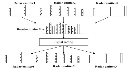
Figure 1.
Sketch map of signal sorting.
Suppose pulse i and pulse j are to be sorted; is the time interval between the two pulses. The sketch map of reconstruction signals is shown in Figure 2.
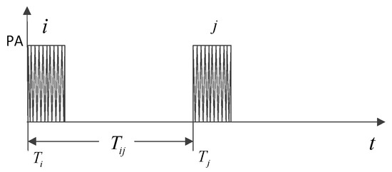
Figure 2.
Sketch map of signal reconstruction.
Suppose and are the RF of the pulse i and pulse j; is the sampling frequency (Fs). After discrete sampling, pulse i and pulse j can be expressed as below:
where is the number of sampling points between two pulses, . and denote the normalized frequency, , . and are the initial phase of pulse i and pulse j (when t = 0). N is the total signal-sampling points.
Without considering the influence of noise, the reconstruction signals of the pulse i and pulse j can be expressed as below:
In terms of the coherent characteristics of coherent radar, if pulse i and pulse j are coherent, their initial phase needs satisfy the following relationship [22,23]:
where denotes the initial phase of the radar emitter and is the propagation-delay time of the first received pulse.
From the model of signal sorting, it can be seen that sorting of any two pulses in a pulse train is based on some related information between the two pulses. In view that coherence is a kind of information between the two pulses, it represents the correlation and continuity of the initial phase between the two pulses. Therefore, coherent characteristics can be extracted as a feature parameter for signal sorting.
2.2. Frequency-Domain Modeling of Coherent Characteristics
For modeling of coherent characteristics, there are two purposes for building a model of frequency domain. The first is because the electromagnetic environment is complex, and there are all kinds of disturbances; if the coherent feature is extracted directly from the time-domain waveform of the radar signal, it is easy for it to be affected by noise. The second is that in frequency domain, the energy distribution of the signal is more concentrated, which can better reflect the essential characteristics of the signal. Discrete Fourier transform (DFT) has many advantages, such as a small amount of computation, high efficiency and phase information that can be well-preserved [24]. Therefore, DFT was adopted to realize the modeling of coherent characteristics to find the difference of spectrum image between coherent and noncoherent signals.
The function of DFT is shown as below:
where is the normalized angular frequency, .
Suppose ; then, substituting Equation (3) into Equation (5), the spectrum analysis of the reconstructed signal based on DFT can be computed as below:
where and denote the normalized angular frequency of pulse i and pulse j, , . In Equation (6), it is noted that if pulse i and pulse j are from the same radar emitter, and satisfy the relationship of Equation (4). When these parameters, such as , are determined, the spectrum image of the reconstruction signals is definite, and it has the superposition in amplitude. But if pulse i and pulse j are not from the same radar emitter, and do not satisfy the relationship of Equation (4); the spectrum image is random and the amplitude is not additive. That is to say, the characteristic difference between coherent and noncoherent signals is mainly reflected in distribution of spectrum energy.
Take two groups of simulation signals: signals in Group 1 are coherent, while signals in Group 2 are noncoherent. The signal parameters of two groups of simulation signals are the same: PA = 1, RF = 27.5 MHz, PW = 2 μs, PRI = 50 μs, Fs = 100 MHz. The spectrum images of coherent and noncoherent signals based on DFT without noise are shown in Figure 3.
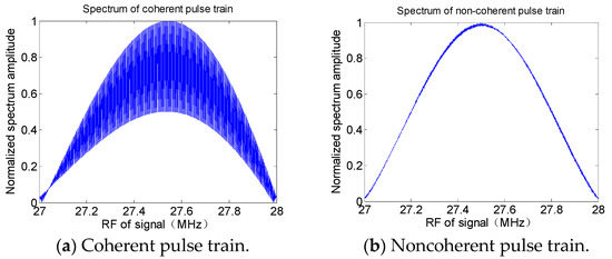
Figure 3.
Spectrum image of coherent and noncoherent pulse train.
In Figure 3, it can be seen that there are obvious differences in energy distribution of the spectrum images between the coherent and noncoherent pulse trains. Because the initial phase of the coherent pulse train is continuous and stable, the spectrum energy has good superposition, while the spectrum energy distribution of the noncoherent pulse train is random. Simulation results are consistent with the theoretical analysis. Therefore, it can be concluded that the difference of energy distribution in spectrum images can be used as a feature for signal sorting. The next work is defining a feature description word (FDW) to describe the difference in energy distribution between the spectrum images.
3. Coherent-Feature Extraction
3.1. Spectrum-Image Pretreatment
The purpose of the spectrum-image pretreatment is to reduce the influence of noise and redundancy and enhance the useful information of the spectrum image. It is more conducive to feature extraction. The spectrum-image pretreatment [25] steps are given as below.
Step 1: Image normalization. The gray value of the spectrum image is normalized to reduce the imbalance between the gray values.
Step 2: Image denoising. An adaptive Wiener filter (AWF) is used to kick off the noise of the spectrum image.
Step 3: Image binarization. The gray image is binarized to enhance the contrast of the coherent and noncoherent signal spectrum images.
Step 4: Image clipping. Remove the redundant information from the image to improve the operation speed.
3.2. Central-Moment-Feature Extraction
In image-processing technology, the central moment (CM) is a kind of image-description word which can describe the shape features of an image, and it can describe a lot of geometric features of an image. The central moments of an image in each order have clear physical meaning [26]. denotes the area of the image. and denote the center of gravity in horizontal and vertical directions. denotes the inclination of an image. and denote the extension in horizontal and vertical directions. and denote the equilibrium in horizontal and vertical directions. Because the difference between spectrum images of coherent and noncoherent signals is only reflected in the vertical extension, the vertical extension of the spectrum image of coherent signals is greater than that of noncoherent signals. Therefore, the normalized central moment (NCM) can be used as the feature parameter to describe the difference between two spectrum images. Suppose is the binary image after image pretreatment, and its size is , . The normalized central moment (NCM) can be computed as below:
The sketch map of the algorithm of central-moment-feature extraction is shown in Figure 4.
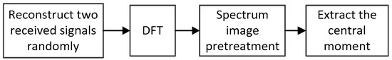
Figure 4.
Sketch map of central moment feature extraction.
3.3. Stability and Adaptability Analysis of the NCM
In order to validate the stability and adaptability of the NCM feature, two simulation experiments are presented. The first was to calculate the results of the NCM feature in different SNRs and to check its stability. The second was to verify whether the NCM-feature-extraction algorithm was suitable for other signal types.
Simulation Experiment 1: Take 200 groups of coherent and noncoherent simulation signals as experimental data. Pulses in Pulse Train 1 are coherent, while pulses in Pulse Train 2 are noncoherent. Parameters and signal type of the two pulse trains are the same; parameters are shown in Table 1.

Table 1.
Parameters of simulation signals.
According to the algorithm of central-moment-feature extraction, the results of the NCM of coherent and noncoherent spectrum images in different SNRs (from 0 dB to 20 dB, interval 5 dB) were computed. Results are shown in Figure 5.
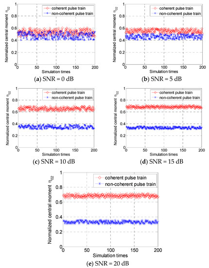
Figure 5.
Normalized central moment (NCM) of spectrum image in different signal-to-noise ratios (SNRs).
From Figure 5, it can be seen that the NCMs of coherent and noncoherent signal spectrum images were distributed respectively in a certain range. When SNR = 0 dB, their NCMs were overlapped; it could not distinguish the difference very well. When SNR ≥ 5 dB, the difference in NCMs between the coherent and noncoherent spectrum images was obvious; the distribution range of the NCM of two distribution ranges decreased gradually, but the separation degree of two characteristic distribution curves increased gradually.
Simulation Experiment 2: In order to demonstrate the adaptability of the feature (NCM)-extraction algorithm for other signal types, take 200 groups of coherent and noncoherent simulation signals; signal types are linear frequency modulation (LFM) with a bandwidth (BW) of 10 MHz and frequency-agile signal (FAS), and each pulse train has two frequency values. Signal parameters are shown in Table 2 and Table 3.
Table 2.
Parameters of linear frequency modulation (LFM) signals.
Table 3.
Parameters of frequency-agile signals (FAS).
According to the algorithm of central moment feature extraction, taking the mean value of 200 groups of simulation results, the relationship between the NCM and the SNR of the two experiments is shown in Figure 6.
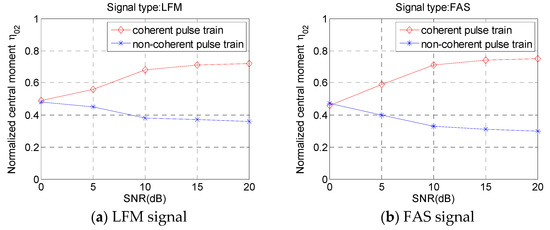
Figure 6.
Results of NCM in different SNRs.
As can be seen from Figure 6, two signals of different modulation types had similar rules. With the increase of the SNR, the NCM of the coherent signal spectrum image increased, while the NCM of the noncoherent signal spectrum image decreased. The NCMs of distribution curves between the coherent and noncoherent signals were obviously separated, and they tended to be stable when reaching a certain SNR.
From the simulation analysis above, it can be concluded that the NCM of the spectrum image can be used as the coherent feature to distinguish the coherent and noncoherent signals of different signal types. The NCM feature not only can be used as a new feature for signal sorting, but also it can be utilized as a supplement for the five typical parameters to improve the sorting accuracy rate. Meanwhile, we can see the NCMs of the coherent signals were basically greater than 0.5, while those of the noncoherent signals were almost less than 0.5, according to Figure 5 and Figure 6. Therefore, the discrimination threshold of the NCM can be set as 0.5 for signal sorting. When the NCM is greater than 0.5, it is considered a coherent pulse train. When the NCM is less than 0.5, it is considered a noncoherent pulse train.
4. Simulation
In this section, two experiments were performed to validate the effectiveness of the proposed NCM feature. The first one was to demonstrate the sorting capability of the NCM feature, and the support vector machine (SVM) was applied to signal sorting. The second was combining the NCM feature and the existing parameters in multiparameter combined sorting (MPCS) to solve the problem of combining-batch and increasing-batch in signal sorting. It is noted that the existing parameters are PA, RF, PW, PRI, AOA and the intrapulse feature. The sketch map of signal sorting based on the NCM feature is shown in Figure 7.
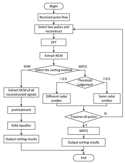
Figure 7.
Sketch map of signal sorting based on NCM.
4.1. Performance Evaluation of Experiment 1
In this experiment, the SVM classifier was adopted for signal sorting. All data were composed of 300 samples containing three pulse trains from the emitter-sample repository. Pulse Train 1 was from Radar Emitter 1; Pulse Train 2 and Pulse Train 3 were from the same radar emitter. The other parameters of the samples are listed in Table 4.
Table 4.
Signal parameters of Experiment 1.
In the SVM classifier [27], the radial basis function (RBF) was selected as the kernel function; the parameter of the kernel function was . The penalty coefficient was C = 8. In three hundred samples, one hundred and twenty samples were used for training, and all remaining samples were utilized for validation. The sorting results in terms of the SVM classifier in different SNRs are shown in Figure 8.
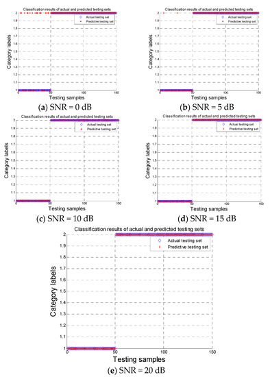
Figure 8.
Sorting results based on support vector machine (SVM) classifier in different SNRs.
The relationship between the sorting accuracy and SNR is shown in Figure 9.
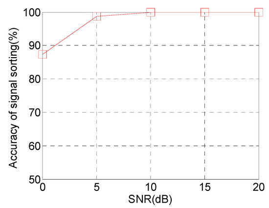
Figure 9.
Accuracy of signal sorting in different SNRs.
From Figure 8 and Figure 9, it can be seen that when SNR = 0 dB, the misclassification was serious in the sorting results. With the increases in the SNR, the accuracy of sorting increased gradually. When SNR ≥ 5 dB, the accuracy of signal sorting could arrive at 98.7%. It could obtain the accurate sorting results that the three pulse trains were from two radar emitters.
4.2. Performance Evaluation of Experiment 2
In this experiment, the NCM feature was combined with the existing parameters to solve the problem of “combining-batch” and “increasing-batch” in signal sorting and improve the accuracy of signal sorting. Take three simulation scenes to verify the performance of signal sorting based on the NCM feature and the existing parameters.
Simulation Scene 1: Three radar emitters with the same working mode were selected for validating the sorting capability of combining the NCM feature and the existing parameters; the working mode was PRI staggering. All testing samples were from the emitter-sample repository. Signal parameters are shown in Table 5.
Table 5.
Signal parameters of Scene 1.
Simulation Scene 2: Frequency-agile radar emitter was utilized to check the sorting capability of combining the NCM feature and the existing parameters. There were one hundred and eighty pulses transmitted from the frequency agile radar; frequency values were 26 MHz, 31 MHz and 36 MHz, and Fs was 100 MHz. The other parameters of the frequency-agile signal are shown in Table 6.
Table 6.
Signal parameters of Scene 2.
Simulation Scene 3: Three pulse trains from two radar emitters were used to present the sorting accuracy of combining the NCM feature and the existing parameters. The signal parameters of the two radar emitters are listed in Table 4.
If the existing five parameters and intrapulse feature were used for signal sorting, in Simulation Scene 1, it was easily misjudged as only one radar emitter, which is the phenomenon of combining-batch. It was also more easily misjudged that the three pulse trains were from three radar emitters in Simulation Scene 2; that is the phenomenon of increasing-batch. In Simulation Scene 3, it was easily misjudged that Pulse Train 1 and Pulse Train 3 were coming from the same radar emitter and that Pulse Train 2 was from another radar emitter. When the NCM feature was combined with the existing parameters for signal sorting, the phenomena of “combining-batch” and “increasing-batch” in Simulation Scene 1 and Scene 2 could be solved easily. Meanwhile, the accuracy of signal sorting was improved in Simulation Scene 3. The probabilities of combining-batch and increasing-batch in different SNRs are shown in Figure 10 and Figure 11. The accuracy of signal sorting in different SNRs is shown in Figure 12.
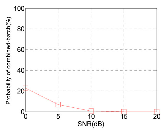
Figure 10.
Probability of combining-batch in different SNRs.
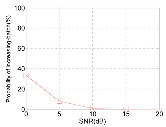
Figure 11.
Probability of increasing-batch in different SNRs.
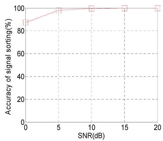
Figure 12.
Accuracy of signal sorting in different SNRs.
From Figure 10, Figure 11 and Figure 12, it can be seen that by combining the NCM with the existing parameters for signal sorting, the probabilities of increasing-batch and combining-batch were reduced, and the accuracy of signal sorting was improved. When SNR = 5 dB, the probabilities of increasing-batch and combining-batch were reduced to 6.8% and 7.9%, and the accuracy of signal sorting was improved to 98.2%. When SNR = 10 dB, the accuracy of signal sorting could arrive at 99.7%. Therefore, it can be concluded that the signal-sorting method based on the coherent feature (NCM) not only can solve the problem of increasing-batch and combining-batch effectively, it also can improve the accuracy of signal sorting.
5. Conclusions
Aiming at the problem of low sorting accuracy of the traditional five feature parameters in signal sorting, a new feature-extraction method based on the coherent characteristics of coherent radar was proposed in this paper. DFT and image-process technology were used to extract the new feature. Simulation results showed that the proposed feature not only could be used as a new feature for signal sorting, but also it could be utilized as a supplement for five typical parameters to solve the problem of increasing-batch and combining-batch. Further work will focus on applying the new extracted feature to signal sorting in an actual complex electromagnetic environment and, through the practical measured data, further validating the sorting performance of the extracted feature.
Author Contributions
Project administration, X.Z.; Supervision, L.T.; Writing—original draft, J.X.; Writing—review & editing, L.J. All authors have read and agreed to the published version of the manuscript.
Funding
This work was supported in part by the National Nature Science Foundation of China (grant number 61976113).
Conflicts of Interest
The authors declare no conflict of interest.
References
- Zhang, J.; Wang, F.; Dobre, O.A.; Zhong, Z. Specific emitter identification via Hilbert-Huang transform in signal hop and relaying scenarios. IEEE Trans. Inf. Forensics Secur. 2016, 11, 1192–1205. [Google Scholar] [CrossRef]
- Zhou, Z.W.; Huang, G.M.; Wang, X.B.; Man, X. Specific emitter identification based on joint collaborative representation. Syst. Eng. Electron. 2019, 41, 724–729. [Google Scholar]
- Satija, U.; Trivedi, N.; Biswal, G.; Ramkumar, B. Specific emitter identification based on variational mode decomposition and spectral features in signal hop and relaying scenarios. IEEE Trans. Inf. Forensics Secur. 2019, 14, 581–591. [Google Scholar] [CrossRef]
- Touati, N.; Tatkeu, C.; Rivenq, A.; Thierry, C.; El Hillali, Y. Multi-user radar waveforms based on doubly coded Costas signals. IET Radar Sonar Navig. 2017, 11, 277–284. [Google Scholar] [CrossRef]
- Yuan, Y.; Cui, G.; Ge, M.; Yu, X.; Kong, L. Active repeat jamming suppression via multi-static radar elliptic-hyperbolic location. In Proceedings of the 2017 IEEE Radar Conference, Seattle, WA, USA, 8–12 May 2017; Institute of Electrical and Electronics Engineers Inc.: Seattle, WA, USA, 2017; pp. 692–697. [Google Scholar]
- Yin, L.; Pan, J.; Jiang, Q. A Study on Sorting of Radar-Signal Based on Fuzzy Clustering. Fire Control Command Control. 2014, 39, 52–57. [Google Scholar]
- Zhang, R.; Xia, H.P. Radar Signal Sorting Algorithm of a New K-means Clustering. Mod. Def. Technol. 2015, 43, 136–141. [Google Scholar]
- Li, Y.D.; Xiao, L.Z.; Li, J.M.; Pu, J.F. A method of complex Radar Signal Based on Grid Clustering. Mod. Def. Technol. 2013, 41, 124–128. [Google Scholar]
- Li, T.; Zhang, S.; Ren, Y.; Li, X.; Ren, Y.; Zhang, C. A Lightning location algorithm based on adaptive density clustering analysis. Sci. Technol. Eng. 2018, 18, 53–59. [Google Scholar]
- Xiao, Y.; Wang, H.; Xu, W. Parameter Selection of Gaussian Kernel for One-Class SVM. IEEE Trans. Cybern. 2015, 45, 941–953. [Google Scholar] [CrossRef]
- Ding, L.; Wang, S.; Wang, F.; Zhang, W. Specific emitter identification via convolutional neural networks. IEEE Commun. Lett. 2018, 22, 2591–2594. [Google Scholar] [CrossRef]
- Jin, W.D.; Chen, C.L. Research on Radar Signal Sorting based on Ensemble Deep Learning. J. Syst. Simul. 2019, 9, 1868–1874. [Google Scholar]
- Kishore, T.R.; Rao, K.D. Automatic Intra Pulse Modulation Classification of Advanced LPI Radar Waveforms. IEEE Trans. Aerosp. Electron. Syst. 2017, 53, 901–914. [Google Scholar] [CrossRef]
- Liu, K.; Han, J.B.; Huang, Q.H. Sorting Radar Signal Based on the Improved Resemblance Coefficient and Singular Spectrum Entropy. Mod. Radar 2015, 37, 80–85. [Google Scholar]
- Yildirim, A. Method for estimating the central frequency of phase-coded radar signals. IET Signal Process. 2016, 10, 1073–1081. [Google Scholar] [CrossRef]
- Ren, Y.; Liao, L.; Maybank, S.J.; Zhang, Y.; Liu, X. Hyper spectral Image Spectral-Spatial Feature Extraction via Tensor Principal Component Analysis. IEEE Geosci. Remote Sens. Lett. 2017, 14, 1431–1435. [Google Scholar] [CrossRef]
- Cui, Y.C.; Yang, J.N.; Lv, J.J.; Wang, W. A Fractal Feature Extraction Algorithm Based on Empirical Mode Decomposition. J. Detect. Control. 2016, 38, 104–108. [Google Scholar]
- Tian, C.J.; Pu, Y.W.; Guo, Y.P.; Shi, Y. A Novel feature Extraction Method for the Slice of Ambiguity Function Main Ridge of Radar Signals Based on Graphic Contours. Acta Armamentarii 2018, 39, 2280–2288. [Google Scholar]
- Bai, H.; Zhao, Y.; Hu, D.; Xu, Y. Radar Emitter Recognition Based on Image Feature of Choi-Williams Time-Frequency Distribution. J. Data Acquis. Process. 2012, 27, 480–485. [Google Scholar]
- Yong, Y.W.; Hoon, P.J.; Woo, B.J.; Cheol, K.S.; Hoon, M.N. Automatic feature extraction from jet engine modulation signals based on an image processing method. Radar Sonar Navig. Iet 2015, 9, 783–789. [Google Scholar] [CrossRef]
- Ren, D.F.; Zhang, T.; Han, J. Specific emitter identification based on ITD and texture analysis. J. Commun. 2017, 38, 160–168. [Google Scholar]
- Han, J.; He, M.H.; Guo, L.R.; Wei, Q.Y. Sorting Method Based on Coherent Radar Signal Auto-correlation Function. J. CAEIT. 2015, 2, 204–208. [Google Scholar]
- Ru, X.H.; Liu, Z.; Jiang, W.L.; Huang, Z.T. Recognition performance analysis of instantaneous phase and its transformed features for radar emitter identification. IET Radar Sonar Navig. 2016, 10, 945–952. [Google Scholar] [CrossRef]
- Bai, H.; Zhao, Y.J.; Hu, D.X. Radar Signal Recognition Based on the Local Binary Pattern Feature of Time-frequency Image. J. Astronaut. 2013, 34, 139–146. [Google Scholar]
- Guo, L.R.; He, M.H.; Yu, C.L.; Wang, B.Q. Describe of Frequency Agility Radar Signal Coherent Characteristic. Fire Control Command Control. 2015, 40, 24–27. [Google Scholar]
- Maddala, K.T.; Moss, R.H.; Stoecker, W.V.; Hagerty, J.R.; Cole, J.G.; Mishra, N.K.; Stanley, R.J. Adaptable Ring for Vision-Based Measurements and Shape Analysis. IEEE Trans. Instrum. Meas. 2017, 66, 746–756. [Google Scholar] [CrossRef]
- Vanhoy, G.; Schucker, T.; Bose, T. Classification of LPI radar signals using spectral correlation and support vector machines. Analog Integr. Circuits Signal Process. 2017, 91, 305–313. [Google Scholar] [CrossRef]


© 2020 by the authors. Licensee MDPI, Basel, Switzerland. This article is an open access article distributed under the terms and conditions of the Creative Commons Attribution (CC BY) license (http://creativecommons.org/licenses/by/4.0/).